Avocent® ACS 6000 Advanced Console Server
Installer/User Guide
Emerson, Emerson Network Power and the Emerson Network Power logo are trademarks or service marks of Emerson Electric Co. Avocent, the Avocent logo and Cyclades are trademarks or service marks of Avocent Corporation or its affiliates in the U.S. and other countries. Liebert is a trademark and service mark of Liebert Corporation. All other marks are the property of their respective owners. This document may contain confidential and/or proprietary information of Avocent Corporation, and its receipt or possession does not convey any right to reproduce, disclose its contents, or to manufacture or sell anything that it may describe. Reproduction, disclosure, or use without specific authorization from Avocent Corporation is strictly prohibited. ©2014 Avocent Corporation. All rights reserved.
i
TABLE OF CONTENTS
Introduction 1
Features and Benefits 1
Access options 1
Web manager 2
IPv4 and IPv6 support 2
Flexible users and groups 3
Security 3
Authentication 3
VPN based on IPSec with NAT traversal 3
Packet filtering 3
SNMP 4
Data logging, notifications, alarms and data buffering 4
Power management 4 Auto discovery 4 FIPS module 4 Configuration Example 4 Installation 7 Getting Started 7
Supplied with the console server 7
Additional items needed 7
Rack Mounting 7
Connecting the Hardware 8
Console server connectors 8
Connecting device consoles or modems to serial ports 10
Turning On the Console Server 11
AC power 11
DC power 12
Configuring a Console Server 13
Using Telnet or SSH 13
Accessing the Console Server via the Web Manager 17
Web Manager Overview for Administrators 17
Wizard Mode 18 Expert Mode 20 Access 20 System Tools 21 System 22 Security 22
Date and Time 26
Help and Language 27
General 27
Information 28
Usage 29
Network 29
Settings 29
Devices 29
IPv4 and IPv6 static routes 30
Hosts 30 Firewall 31 IPSec(VPN) 33 SNMP Configuration 34 Ports 35 Serial ports 35 Auxiliary ports 42 CAS Profile 42 Dial-in Profile 45 Dial-out Profile 47 Pluggable Devices 48 Device configuration 49 Authentication 49 Appliance authentication 50 Authentication servers 51
Users Accounts and User Groups 53
Local accounts 53
User groups 54
DSView software access rights 61
Event Notifications 61 Event List 61 Event Destinations 62 Trap Forward 62 Data Buffering 63 Appliance logging 63 Sensors 64 Power Management 64 PDUs 65 Login 67 Outlet Groups 67 Network PDUs 68 Active Sessions 68 Monitoring 69 Change Password 69
Web Manager Overview for Regular Users 70
Appendices 71
...iii
Recovering a Console Server's Password 72
Port Information for Communication with the DSView Software 73
Accessing a Console Server with a DSView Software Installation via Dial-up 74
Installing DSView software with an OOB back door 74
Configuring dial-up for a console server 74
Internal Modem 77
AT+MS modulation selection 80
Set telephone extension option 81
AT S registers 81
Basic modem result codes 82
Digital line guard 82
Sleep mode operation 83
Disconnecting a call 83
Selecting country codes 83
Using caller ID 84
Introduction
The Avocent® ACS 6000 advanced console server is a 1U appliance that serves as a single point for access and administration of connected devices, such as target device consoles, modems and power devices. Console servers support secure remote data center management and out-of-band management of IT assets from any location worldwide.
NOTE:Unless noted, references to a console server refer to all models in the 60XX series.
Console servers provide secure local (console port) and remote (IP and dial-up) access. The console servers run the Linux®operating system with a persistent file system in Flash memory, and can be upgraded from either FTP or a DSView™4 management software server.
NOTE:Unless otherwise noted, all references to DSView software in this document refer to version 4 or greater.
Multiple administrators can be logged into the console server at the same time and can use the web manager, the Command Line Interface (CLI utility) or DSView software to access and configure the console server.
Some models feature two PC card/slots to support modem, Ethernet, fast Ethernet (fiber optic) and storage PC cards (16 bit and 32 bit). One USB port supports modem (V.92 and Wireles), storage devices and USB hubs. Two fast Ethernet ports support connections to more than one network or configuration of Ethernet bonding (failover) for redundancy and greater reliability. For dial-in and secure dial-back with Point-to-Point Protocol (PPP), optional internal modems can be factory installed, or you can use external modems or wireless modem CardBus devices.
Features and Benefits
Access options
Secure access is available through the following local (analog console port) and remote (digital IP and dial-up) options:
• LAN/WAN IP network connection.
• Dial-up to a factory-configured internal modem (optional), a modem connected either to a serial port or the AUX port (which is only possible when an internal modem is not installed), or to a PC phone card installed in one of the PC card slots (if applicable) or in the USB port or a wireless modem.
• Target device connection. An authorized user can make a Telnet, SSH v1, SSH v2 or Raw connection to a target device. For Telnet or SSH to be used for target device connections, the Telnet or SSH service must be configured in the Security Profile that is in effect.
• Console server console connection. An administrator can log in either from a local terminal or from a computer with a terminal emulation program that is connected to the console port and can use the CLI utility. The CLI utility prompt (--|- cli>) displays at login.
More than one administrator can log into the console server and have an active CLI or web manager session. All sessions receive the following warning message when the configuration is changed by another administrator or by the system:The appliance configuration has been altered from outside of your session.Upon receipt of this message, each administrator needs to verify that changes made during the session were saved.
Web manager
Users and administrators can perform most tasks through the web manager (accessed with HTTP or HTTPS). The web manager runs in Microsoft®Internet Explorer®, Mozilla®Firefox®, and Apple®Safari®on any supported computer that has network access to the console server. The list of supported client browsers and their versions are available in the release notes.
IPv4 and IPv6 support
The console server supports dual stack IPv4 and IPv6 protocols. The administrator can use the web manager or CLI to configure support for IPv4 addresses only or for both IPv4 and IPv6 addresses. The following list describes the IPv6 support provided in the console server:
• DHCP
• Dial-in and dial-out sessions (PPP links)
• DSView software integration
• eth0 and eth1 Ethernet interfaces
• Firewall (IP tables)
• HTTP/HTTPs
• Linux kernel
• Remote authentication: Radius, Tacacs+, LDAP and Kerberos servers
• SNMP
• SSH and Telnet access
• Syslog server
Introduction...3
Flexible users and groups
An account can be defined for each user on the console server or on an authentication server. The admin and root users have accounts by default, and either can add and configure other user
accounts. Access to ports can be optionally restricted based on authorizations an administrator can assign to custom user groups. For more information, seeUsers Accounts and User Groupson page 53.
Security
Security profiles determine which network services are enabled on the console server.
Administrators can either allow all users to access enabled ports or allow the configuration of group authorizations to restrict access. You can also select a security profile, which defines which
services (FTP, ICMP, IPSec and Telnet) are enabled and SSH and HTTP/HTTPS access. The administrator can select either a preconfigured security profile or create a custom profile. For more information, seeSecurityon page 22.
Authentication
Authentication can be performed locally, with One Time Passwords (OTP), a remote Kerberos, LDAP, NIS, RADIUS, TACACS+ authentication server or a DSView server. The console server also supports remote group authorizations for the LDAP, RADIUS and TACACS+ authentication methods. Fallback mechanisms are also available.
Any authentication method configured for the console server or the ports is used for authentication of any user who attempts to log in through Telnet, SSH or the web manager. For more information, seeAuthenticationon page 49.
VPN based on IPSec with NAT traversal
If IPSec is enabled in the selected security profile, an administrator can use the VPN feature to enable secure connections. IPSec encryption with optional NAT traversal (which is configured by default) creates a secure tunnel for dedicated communications between the console server and other computers that have IPSec installed. ESP and AH authentication protocols, RSA Public Keys and Shared Secret are supported. For more information, seeIPSec(VPN)on page 33.
Packet filtering
An administrator can configure a console server to filter packets like a firewall. Packet filtering is controlled bychains, which are named profiles with user-defined rules. The console server filter table contains a number of built-in chains that can be modified but not deleted. An administrator can also create and configure new chains.
SNMP
If SNMP is enabled in the selected security profile, an administrator can configure the Simple Network Management Protocol (SNMP) agent on the console server to answer requests sent by an SNMP management application.
The console server SNMP agent supports SNMP v1/v2 and v3, MIB-II and Enterprise MIB. For more information, seeSNMP Configurationon page 34.
NOTE:The text files with the Enterprise MIB (ACS6000-MIB.asn) and the TRAP MIB (ACS6000-TRAP-MIB.asn) are available in the appliance under the /usr/local/mibs directory.
Data logging, notifications, alarms and data buffering
An administrator can set up data logging, notifications and alarms to alert administrators of
problems with email, SMS, SNMP trap or DSView software notifications. An administrator can also store buffered data locally, remotely or with DSView management software. Messages about the console server and connected servers or devices can also be sent to syslog servers.
Power management
The console server enables users who are authorized for power management to turn power on, turn power off and reset devices plugged into a connected power distribution unit (PDU). The power devices can be connected to any serial port or to the AUX/Modem port (if an internal modem is not installed). For more information, seePower Managementon page 64.
Auto discovery
An administrator can enable auto discovery to find the hostname of a target connected to a serial port. Auto discovery’s default probe and answer strings have a broad range. An administrator can configure site-specific probe and answer strings. Auto discovery can also be configured through the DSView software.
FIPS module
The 140 series of Federal Information Processing Standards (FIPS) are U.S. government computer security standards that specify requirements for cryptography modules.
The console server uses an embedded FIPS 140-2 validated cryptographic module (Certificate No. 1747) running on a Linux PPC platform per FIPS 140-2 Implementation Guidance section G.5 guidelines. For more information, seeFIPS moduleon page 23.
Configuration Example
Introduction...5
Typical ACS 6000 Advanced Console Server Configuration
Number Description Number Description
1 ACS 6000 advanced console server 8 Phone line
2 Target devices 9 Remote dial-in
client
3 PDU (one or more) 10 Local Area
Network (LAN)
4 Serial port connection 11 LAN firewall
5 PC card (modem, Ethernet or storage - not available on all
models) 12
Remote authentication server
6 Either AUX/Modem or any serial port 13 DSView
client/server 7
Modem ordered and configured internally at the factory -or-external modem (on a device in one of the PC card slots or USB port, or connected to a serial port or the AUX port)
14
Remote/local Windows/Linux computer Typical ACS 6000 Advanced Console Server Configuration Descriptions
Installation
Getting Started
Before installing your ACS 6000 console server, refer to the following list to ensure you have all items that shipped with it , as well as other items necessary for proper installation.
Supplied with the console server
• Quick Installation Guide (QIG)• Power Cord
• RJ-45 to RJ-45 straight-through CAT 5 cable
• RJ-45 to DB-9F cross adaptor
• DB-25 loop-back plug
• RJ-45 to DB-25M cross adaptor
• RJ-45 to DB-25F cross adaptor
• RJ-45 to DM-25M straight-through cable
• Mounting brackets, screws and cord retention clips
• Keyhole mounting kit
• Software License Agreement
• Safety Sheet
Additional items needed
If you are configuring the console server in a standalone configuration, you will also need the following items:
• One or more RJ-45 to RJ-45 CAT 5 straight-through cables
• An RJ-45 to DB-9F straight-through adaptor
• A PC running a terminal emulation program
Rack Mounting
You can mount the console server in a rack or cabinet, or place it on a desktop or other flat surface. For rack or cabinet mounting, two mounting brackets are supplied.
1. Install the brackets at the front or back edges of the console server with the screws provided with the mounting kit.
2. Mount the console server in a secure position.
Bracket Connections for Front Mount Configuration
Connecting the Hardware
Console server connectors
The following figure shows the connectors on the front of the ACS 6000 console server.
Front of the Console Server (ACS 6032 Console Server Shown)
Number Description
1 USB connector
2 LEDs
3 PC card slots (not available on all models) Connectors on the Console Server Front
Installation...9
Label Description
PWR/CPU
• Blue Blinks - During unit boot • Solid - During operation • Off - Power is off
ETH 0/ETH 1
• Amber - Link at 10BaseT speed • Yellow - Link at 100BaseT speed • Green - Link at 1000BaseT speed
• Off - No link/cable disconnected/Ethernet fault
AUX/MODEM
Dual LED: Yellow on top, green on bottom • Yellow - DTR/DCD activity
• Green - TXD and RXD activity • Off - No activity
[One LED for each serial port] Green
• Blinks - Ready, with activity • Solid - Ready
• Off - Not ready LEDs on the Console Server Front
The following figure shows the rear connectors on the console server.
Rear of the Console Server (ACS 6032 Console Server Shown)
Number
Description
1 Power supplies (dual AC shown).
2 Serial ports (32 ports shown). Models come with 4, 8, 16, 32 or 48 serial ports.
3 ETH 1 10/100M/1G Ethernet port. Can be connected to a second network or used for failover. 4
AUX/Modem port. If an optional internal modem is ordered, this port is defined as a V.92 modem at the factory; otherwise, the port is factory-defined as RS-232 with an RJ-45 ACS console server pinout and can be used to connect either an external modem or a power device.
5 ETH0 10/100M/1G Ethernet port for remote IP access.
6 Console port. Allows for local administration and access to connected devices through a terminal or a computer with a terminal emulator.
Connecting device consoles or modems to serial ports
Use CAT 5 or greater cables and DB-9 or DB-25 console adaptors as needed to connect target device consoles or modems to the serial ports on the console server.
The console server supports the Cisco®serial port pinout configuration, which is disabled by
default. If a Cisco cable is connected to a port, an administrator must enable the Cisco pinout for the port. An administrator can selectExpert - Ports - Serial Ports - (SetCAS or SetPower) - Physicalto open the Physical Settings screen, then checkEnable Cisco RJ Pin-Out.
The following tables show serial port pinout information.
Pin No. Signal Name Input/Output
1 RTS OUT 2 DTR OUT 3 TxD OUT 4 GND N/A 5 CTS IN 6 RxD IN 7 DCD/DSR IN
8 Not Used N/A
ACS Console Server Serial Port Pinout
Pin No. Signal Name Input/Output
1 CTS IN
2 DCD/DSR IN
3 RxD IN
4 GND N/A
5 Not Used N/A
6 TxD OUT
7 DTR OUT
8 RTS OUT
Cisco Serial Port Pinout
To connect devices, modems and PDUs to serial ports:
Make sure the crossover cable used to connect a device has the same pinout type that is configured in the software for the port (either Cyclades or Cisco).
1. Make sure the devices to be connected are turned off.
2. Use CAT 5 or greater crossover cables to connect the devices to the console server, using an adaptor, if necessary.
Installation...11
3. To connect modems, use straight-through CAT 5 or greater cables, with an appropriate connector or adaptor (USB, DB-9 or DB-25) for the modem.
NOTE:To comply with EMC requirements, use shielded cables for all port connections.
WARNING:Do not turn on the power on the connected devices until after the console server is turned on.
To daisy chain PDUs to a console server:
This procedure assumes that you have one PDU connected to a serial port on a console server.
NOTE:Daisy chaining is not possible with SPC PDUs. ServerTech PDUs will allow only one level (Master and Slave) of daisy chaining.
1. Connect one end of a UTP cable with RJ-45 connectors to the OUT port of the connected PDU.
2. Connect the other end of the cable to the IN port of the chained PDU. Repeat both steps until you have connected the desired number of PDUs.
NOTE:For performance reasons, Avocent recommends connecting no more than 128 outlets per serial port.
Turning On the Console Server
The console server is supplied with single or dual AC or DC power supplies.
WARNING:Always execute the shutdown command through the web manager, CLI or DSView software under the Overview/Tools node before turning the console server off, then on again. This will ensure the reset doesn't occur while the file system in Flash is being accessed, and it helps avoiding Flash memory corruptions.
AC power
To turn on a console server with AC power:
1. Make sure the console server is turned off.
2. Plug the power cable into the console server and into a power source. 3. Turn the console server on.
DC power
DC power is connected to DC-powered console servers by way of three wires: Return (RTN), Ground (GND) and -48 VDC.
WARNING:It is critical that the power source supports the DC power requirements of your console server. Make sure that your power source is the correct type and that your DC power cables are in good condition before proceeding. Failure to do so could result in personal injury or damage to the equipment.
The following diagram shows the connector configuration for DC power.
DC Power Connection Terminal Block
Number Description Number Description
1 Power switch 3 GND (Ground)
2 RTN (Return) 4 -48 VDC
DC Power Connection Details
To turn on a console server with DC power:
1. Make sure the console server is turned off.
2. Make sure DC power cables are not connected to a power source.
3. Remove the protective cover from the DC power block by sliding it to the left or right. 4. Loosen all three DC power connection terminal screws.
5. Connect your return lead to the RTN terminal, your ground lead to the GND terminal and your -48 VDC lead to the -48 VDC terminal and tighten the screws.
6. Slide the protective cover back into place over the DC terminal block.
7. If your console server has dual-input DC terminals, repeat steps 3-6 for the second terminal. 8. Connect the DC power cables to the DC power source and turn on the DC power source. 9. Turn on the console server.
Installation...13
10. Turn on the power switches of the connected devices.
Configuring a Console Server
A console server may be configured at the appliance level through the command line interface accessed through the CONSOLE or Ethernet port. All terminal commands are accessed through a terminal or PC running terminal emulation software.
NOTE:To configure using DSView software, see the DSView Software Installer/User Guide. To configure using the console server’s web manager, see Chapter 3. To configure using Telnet or SSH, see the ACS 6000 Command Reference Guide.
To connect a terminal to the console server:
1. Using a null modem cable, connect a terminal or a PC that is running terminal emulation software (such as HyperTerminal®) to the CONSOLE port on the back panel of the console
server. An RJ-45 to DB9 (female) cross adaptor is provided.
The terminal settings are 9600 bits per second (bps), 8 bits, 1 stop bit, no parity and no flow control.
2. Turn on the console server. When the console server completes initialization, the terminal will display the login banner plus the login prompt.
Using Telnet or SSH
An authorized user can use a Telnet or SSH client to make a connection directly to the console of a device if all of the following are true:
The Telnet or SSH:
• protocol is enabled in the selected security profile
• protocol is configured for the port
• client is available, and it is enabled on the computer from which the connection is made
To use Telnet to connect to a device through a serial port:
For this procedure, you need the username configured to access the serial port, the port name (for example, 14-35-60-p-1), device name (for example, ttyS1), TCP port alias (for example, 7001) or IP port alias (for example, 100.0.0.100) and the hostname of the console server or its IP address.
To use a Telnet client, enter the information in the dialog boxes of the client.
# telnet [hostname|IP_address]
login:username:[portname | device_name]
-or-# telnet [hostname | IP_address]TCP_Port_Alias
login:username
-or-# telnetIP_Port_Alias
login:username
To close a Telnet session:
Enter the Telnet hotkey defined for the client. The default isCtrl ] + qto quit, or enter the text session hotkey for the CLI prompt and then enterquit.
To use SSH to connect to a device through a serial port:
For this procedure, you need the username configured to access the serial port, the port name (for example, 14-35-60-p-1), TCP port alias (for example, 7001), device name (for example, ttyS1), and the hostname of the console server, IP address or IP Port alias (for example, 100.0.0.100).
To use an SSH client, enter the information in the dialog boxes of the client.
-or-To use SSH in a shell, enter the following command:
ssh -lusername:port_name [hostname | IP_address]
-or-ssh -lusername:device_name [hostname | IP_address]
-or-ssh -lusername:TCP_Port_Alias [hostname | IP_address]
-or-ssh -lusername IP_Port_Alias
Installation...15
At the beginning of a line, enter the hotkey defined for the SSH client followed by a period. The default is~. Or, enter the text session hotkey for the CLI prompt and then enterquit.
Accessing the Console Server via the Web
Manager
Once you’ve connected your ACS 6000 console server to a network, you can access the console server with its web manager. The web manager provides direct access to the console server via a graphical user interface instead of a command-based interface.
NOTE:For instructions on accessing the console server via the CLI or DSView software see the Cyclades ACS 6000 Command Reference Guide or the DSView Software Installer/User Guide.
Web Manager Overview for Administrators
NOTE:For an overview of the web manager for regular users, seeWeb Manager Overview for Regular Userson page 70.
To log into the web manager:
1. Open a web browser and enter the console server IP address in the address field. 2. Log in as eitheradminwith the passwordavocentor asrootwith the passwordlinux.
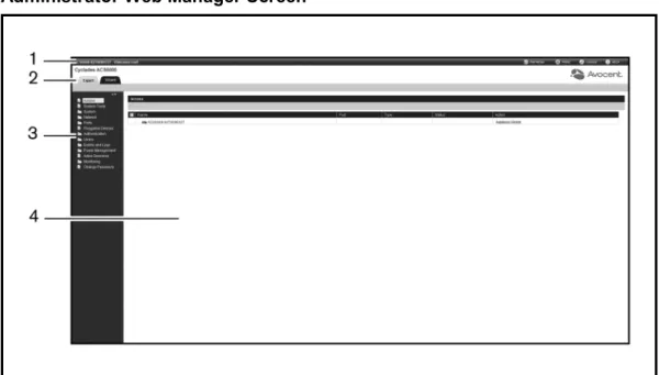
Figure 3.1 shows a typical web manager screen for an administrator and descriptions follow in Table 3.1.
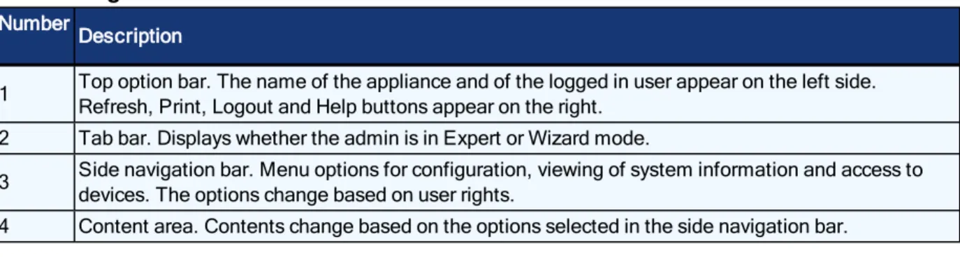
Number
Description
1 Top option bar. The name of the appliance and of the logged in user appear on the left side. Refresh, Print, Logout and Help buttons appear on the right.
2 Tab bar. Displays whether the admin is in Expert or Wizard mode.
3 Side navigation bar. Menu options for configuration, viewing of system information and access to devices. The options change based on user rights.
4 Content area. Contents change based on the options selected in the side navigation bar. Web Manager Screen Areas
Wizard Mode
The Wizard mode is designed to simplify the setup and configuration process by guiding an administrator through the configuration steps. An administrator can configure all ports in the CAS Profile and set the Security Profile, Network and Users Settings using the Wizard.
By default, the first time an administrator accesses the console server through the web manager, the Wizard will be displayed. Subsequent log-ins will open in Expert mode, and once the console server has been configured, Expert mode becomes the default mode. An administrator can toggle between Expert and Wizard modes by clicking the tab bar on the web manager administrator screen.
Figure 3.2 shows a typical screen when an administrator is in Wizard mode.
Wizard Screen
The following procedures describe how to configure the console server from the Wizard.
To configure security parameters and select a Security Profile:
Accessing the Console Server via the Web Manager...19
2. Select the desired Security Profile. If using a Custom Security Profile, click the checkboxes and enter values as needed to configure the services, SSH and HTTP and HTTPS options to conform with your site security policy.
3. Under the Bootp Configuration Retrieval heading, uncheck the box(es) to disable Bootp configuration retrieval and/or live configuration retrieval.
4. If you are not using DSView software to manage the appliance, uncheck theAllow Appliance to be Managed by DSViewbox.
5. ClickNextto configure the Network or click theNetwork,PortsorUserslink to open the appropriate screen.
To configure network parameters:
1. Select theNetworklink in the content area.
2. Enter the Hostname, Primary DNS and Domain in the appropriate fields.
3. Select the IPv4 or IPv6 method for the ETH0 interface. If using Static, enter the Address, Mask and Gateway in the appropriate fields.
4. Enable or disable IPv6 support.
5. ClickNextto configure ports or click on theSecurity,PortsorUserslink to open the appropriate screen.
To configure Ports:
1. Select thePortslink in the content area.
2. Check the box(es) to enable all ports and/or to enable Cisco RJ45 Pin-Out to change the pin-out when a Cisco cable is connected.
3. Use the appropriate drop-down menus to select the values for Speed, Parity, Data Bits, Stop Bits, Flow Control, Protocol, Authentication Type and Data Buffering Status.
4. Select the Data Buffering Type. If using NFS, enter the NFS Server and NFS Path information in the appropriate fields.
5. ClickNextto configure users or click on theNetwork,SecurityorUserslink to open the appropriate screen.
To configure users and change the default user passwords:
WARNING:For security reasons, it is recommended you change the default password for both root and admin users immediately.
1. Select theUserslink in the content area.
2. Click a username (adminorroot) and enter the new password in the Password and Confirm Password fields.
-or-ClickAddto add a user. Enter the new username and password in the appropriate fields.
3. (Optional) To force the user to change the default password, select theUser must change password at next login checkbox.
4. Assign the user to one or more groups.
5. (Optional) Configure account expiration and password expiration. 6. ClickNext.
7. Repeat steps 3-7 as needed to configure new user accounts and assign them to default groups.
NOTE:By default, all configured users can access all enabled ports. Additional configuration is needed if your site security policy requires you to restrict user access to ports.
8. ClickSave,then clickFinish.
Expert Mode
The following tabs are available in the side navigation bar of the web manager when an administrator is in Expert mode.
Access
ClickAccessto view all the devices connected to the console server.
To view and connect to devices using the web manager:
1. SelectAccessin the side navigation bar. The content area displays the name of the console server and a list of names or aliases for all installed and configured devices the user is authorized to access.
2. SelectSerial Viewerfrom the Action column. A Java®applet viewer appears. In a gray area at the top of the viewer, theConnected tomessage shows the IP address of the console server followed by the default port number or alias.
3. Log in if prompted.
The following table describes the available buttons in the Java applet.
Button Purpose SendBreak
To send a break to the terminal
Accessing the Console Server via the Web Manager...21
Button Purpose Disconnect
To disconnect from the Java applet
Select the left icon to reconnect to the server or device; or select the right icon to end the session and disconnect from the Java applet
System Tools
ClickSystem Toolsto display icons which can be clicked to reboot or shut down the console server, upgrade the console server’s firmware, save or restore its configuration or open a terminal session with the console server.
To upgrade a console server's firmware:
1. From http://www.avocent.com, browse to the product updates section and find the firmware for your console server.
2. Save the new firmware to an FTP server or to your desktop.
3. From the sidebar of the console server's web manager, clickSystem Tools, then click
Upgrade Firmware.
4. Download the file from an FTP server by selecting FTP server.
a. In the FTP site field, enter the address of the FTP server where you saved the firmware. b. Enter the username and password for the FTP server in the appropriate fields.
c. Enter the file directory where the firmware is saved and the filename for the firmware in the appropriate fields.
-or-Download the file from your desktop by selecting My Computer.
a. Type the filename for the new firmware or clickBrowseto open a window to browse to the file.
5. ClickDownload. The console server will download the firmware from the specified site and will display a message when the download is complete.
6. ClickInstall.
7. Once the new firmware is installed, reboot the console server.
NOTE:If the page after installation displays empty or blank values, there was not enough memory to upgrade the firmware. Reboot the console server and upgrade the firmware again.
System
ClickSystemto display information about the console server and allow an administrator to configure the console server’s system parameters. The following tabs are listed under System in the side navigation bar.
Security
Security Profile
A Security Profile determines which network services are enabled on the console server.
During initial configuration, the console server administrator must configure security parameters to conform with the site security policy. The following security features can be configured either in the web manager, CLI or the DSView software:
• Configure the session idle time-out
• Enable or disable RPC
• Ability to configure access for all users, or allow the configuration of group authorizations to restrict access
• Select a Security Profile, which defines:
• Enabled services (FTP, ICMP, IPSec and Telnet)
• SSH and HTTP/HTTPS access
• Enable or disable Bootp Configuration retrieval
The administrator can select either a preconfigured Security Profile or create a custom profile.
All the services and the SSH and HTTP/HTTPS configuration options that are enabled and disabled for each Security Profile are shown in the Wizard Security and the System Security -Security Profile pages.
To configure a Security Profile:
1. SelectSystem - Security - Security Profile.
2. In the Idle Timeout field, enter the number of minutes before the console server times out open sessions.
NOTE:This value applies to any user session to the appliance via HTTP, HTTPS, SSH, Telnet or CONSOLE port. It will not overwrite the value configured for the user's authorization group. The new idle time-out will be applied to new sessions only.
Accessing the Console Server via the Web Manager...23
4. Under the Serial Devices heading, select whether port access is controlled by user group authorization or configure port access settings to apply to all users.
5. Under Bootp Configuration retrieval, enable or disable the service.
6. Select the checkbox forCustom,Moderate,OpenorSecureunder the Security Profile heading.
7. Enable/disable SSH authentication via username/password. 8. ClickSave.
DSView software security
You can also configure DSView software security settings. When the console server is managed by the DSView software, the DSView server will supply the certificate to the console server. Under normal conditions, the DSView software will manage the certificate to clear and replace it with a new certificate as needed. If communication with the DSView software is lost, the DSView server will be unable to clear the certificate and the console server cannot be used. Click theClear DSView Certificatebutton to configure the console server in Trust All mode.
To configure DSView software security settings:
1. SelectSystem - Security - DSView.
2. Click theAllow appliance to be managed by DSViewcheckbox and clickSave.
FIPS module
The console server has embedded the FIPS-capable OpenSSL that is the combination of the FIPS Object Module (the FIPS 140-2 validated module) along with a FIPS-compatible OpenSSL (it is a version of the OpenSSL product that is designed for compatibility with the FIPS Object Module API).
If an administrator enables the FIPS module, the console server will use the FIPS Object Module to perform encryption operations. The FIPS module is disabled by default.
When the FIPS module is enabled, the Monitoring - FIPS mode page will show what service
(SSHv2, HTTPS, SNMPv3 and ADSAP2) is in FIPS mode. All security functions and cryptographic algorithms used by the service are performed in FIPS 140-2 Approved mode.
To enable the FIPS module:
1. SelectSystem - Security - FIPS 140.
2. Check the box to Enable the FIPS 140-2 Module and clickSave.
The console server will automatically reboot. During the reboot, the console server will erase SSH keys, update the configuration of HTTPD, SSHD, ADSAP2d and SNMPD files and test the
integrity of the FIPS Object Module. Once the reboot is complete, the console server will accept SSH and HTTPS connections using only FIPS-approved ciphers.
When FIPS is enabled the following restrictions apply:
For SSH sessions:
Protocol version 1 will be disabled.
Triple-DES CBS and AES 128/192/256 are the only encryption ciphers that will be accepted.
HMAC-SHA1 and HMAC-SHA1-96 are the only message integrity algorithms that will be accepted.
Only RSA keys 1024 to 16384 bits will be accepted.
HTTPS sessions will accept only the SSL v 3.1(TLSv1) protocol to establish the SSL tunnel with one of the following encryption ciphers:
AES-256-SHA
AES-128-SHA
Triple DES SHA (DES-CBC3-SHA)
SNMP version 3 requests will be accepted when authentication is SHA and the encryption cipher is AES.
HTTPS Certificate
You can generate a new self-signed certificate or download a signed certificate to the appliance from an FTP server or from your desktop.
To generate a new self-signed certificate:
1. SelectSystem – Security – HTTPS Certificate.
2. Check the radio button next to Generate Self-Signed Certificate.
3. Enter the desired information in the self-signed certificate fields: Country, State/Province, City/Locality, Organization, Organization Unit, Common Name, Email Address and Netscape Comment.
4. ClickGenerate/Download.The generated certificate's information will be displayed. 5. ClickInstall. The certificate will be saved and the browser server will restart to use the new
certificate.
To download a signed certificate:
Accessing the Console Server via the Web Manager...25
2. Check the radio button next to Download Certificate from FTP Server to download the file from the FTP server.
3. Enter all information about the FTP server: FTP site (IP address), Username, Password, File Directory and File Name
-or-Check the radio button next to Download Certificate from My Computer to download the file from your desktop.
4. Enter the filename's path or clickBrowserto browse to the file.
5. ClickGenerate/Download.The generated certificate's information will be displayed. 6. ClickInstall. The certificate will be saved and the browser server will restart to use the new
certificate.
NOTE:The browser server will restart to use the new certificate, all http/https sessions will close and user needs to re-establish the connection.
Bootp Configuration Retrieval
You can set your console server to be reconfigured during boot or at IP renewal.
To generate configuration to be retrieved:
1. ClickSystem Tools - Save Configurationand save the configuration to either an FTP site or locally.
-or-Use the list_configuration command to get the CLI template scripts, edit the configuration of the console server and save it as a text file.
-or-Edit a file with CLI commands and save it.
2. Transfer the saved file to a DHCP server.
3. Configure the DHCP server to transfer the configuration file to the console server.
To reconfigure a console server with bootp:
1. ClickSystem - Security - Security Profile. Under the Bootp Configuration Retrieval heading, ensure the box next to Enabled is checked.
2. Uncheck the box next to Enable Live Configuration. The saved configuration will be retrieved and applied on the next reboot.
-or-Ensure the box next to Enable Live Configuration is checked. The saved configuration will be retrieved and applied on the next IP renewal.
NOTE:You must configure your DHCP server in order to transfer the configuration file to your console server.
Date and Time
The console server provides two options for setting the date and time. It can retrieve the date and time from a network time protocol (NTP) server, or you can set the date and time manually so that the console server’s internal clock is used to provide time and date information.
NOTE:The Current Time displayed in the Date & Time screen shows only the time when the screen was opened. It does not continue to update in real time.
To set the time and date using NTP:
1. ClickSystem - Date And Time. 2. SelectEnable network time protocol.
3. Enter the NTP server site of your choice and clickSave.
To set the time and date manually:
1. ClickSystem - Date And Time. 2. SelectSet manually.
3. Using the drop-down menus, select the required date and time and clickSave.
To set the time zone using a predefined time zone:
1. ClickSystem - Date And Time - Time Zone. 2. SelectPredefined.
3. Select the required time zone from the drop-down menu and clickSave.
To define custom time zone settings:
1. ClickSystem- Date And Time - Time Zone. 2. SelectDefine Time Zone.
Accessing the Console Server via the Web Manager...27
4. Enter the GMT Offset.
5. SelectEnable daylight savings timeif needed.
6. Select or enter the required values for daylight savings time settings and clickSave.
Help and Language
ClickSystem - Help And Languageand use the drop-down menu to select the console server’s language. Enter the full URL of the online help, ending in /index.html, on the local web server in the Online Help URL field. ClickSave.
Online help
When the online help feature is configured for your console server, clicking theHelpbutton from any form on the web manager opens a new window and redirects its content to the configured path for the online help product documentation.
NOTE:Using the online help feature from the Avocent/Cyclades server is not always possible due to firewall configurations, nor is it recommended. It is generally advisable for you to use the online help system provided with the product or download the online help .zip file and run it from a local server.
The system administrator can download the online help from Avocent. For more information on downloading the online help, contact Technical Support.
Once the online help file is obtained (in zip format), the files must be extracted and put in to a user-selected directory under the web server’s root directory. The web server must be publicly
accessible.
NOTE:The default URL for online help is http://global.avocent.com/us/olh/acs6000/v_3.0.0/en/index.html.
General
An administrator can configure a login banner to display when a user begins a SSHv2, Telnet, Console or web manager session.
To create a login banner:
1. Click System - Generalin the side navigation bar. 2. Check the box to enable the login banner.
Boot Configuration
Boot configuration defines the location from which the console server loads the operating system. The console server can boot from its internal firmware or from the network. By default, the console server boots from Flash memory. ClickingSystem- Boot Configurationwill display the Boot
Configuration screen.
If you need to boot from the network, make sure the following prerequisites are met:
• A TFTP or BootP server must be available on the network
• An upgraded console server boot image file must be downloaded from Avocent and made available on the TFTP or BootP server
• The console server must be configured with a fixed IP address
• The boot filename and the IP address of the TFTP or BootP server is known
To configure boot configuration:
1. ClickSystem - Boot Configuration.
2. Under Boot Mode, selectFrom Flash, and selectImage 1orImage 2.
-or-SelectFrom Networkand enter the following information:
• Appliance IP Address: Enter the fixed IP address or a DHCP assigned IP address to the console server.
• TFTP Server IP: Enter the IP address of the TFTP boot server.
• Filename: Enter the filename of the boot firmware.
3. Using the drop-down menu, select whether the Watchdog Timer is enabled. If the Watchdog Timer is enabled, the console server reboots if the software crashes.
4. Using the drop-down menu, select one of the following speeds for both Ethernet 0 Mode and Ethernet 1 Mode: 100BT full, 100BT half, 10BT full, 10BT half or Auto.
5. Using the drop-down menu, select the console port speed and clickSave.
NOTE:Ethernet Mode will be affected after saving. The rest of the configuration will be applied after rebooting.
Information
ClickSystem - Informationto view the console server’s identity, versions, power and CPU information.
Accessing the Console Server via the Web Manager...29
Usage
ClickSystem - Usageto view memory and Flash usage.
Network
ClickNetworkto view and configure the network options for Hostname, DNS, IPv6, Bonding, IPv4 and IPv6 static routes, Hosts, Firewall, IPSec (VPN) and SNMP.
Settings
ClickNetwork - Settingsto make changes to the configured network settings: Hostname, DNS, Bonding, IPv4 Multiple Routing Table.
NOTE:IPv4 Multiple Routing Table allow administrator to configure two networks one for each interface (EHT0 and ETH1) with its own default gateway.
Devices
An administrator can select, enable and configure the IP addresses assigned to the network interfaces and view the MAC address. Besides the two standard Ethernet interfaces, the list of network interfaces includes entries for any Ethernet PC cards that may be installed.
To configure a network device:
1. SelectNetwork - Devices. The Devices screen appears with a list of network interfaces and their status (enabled or disabled).
2. Click the name of the network device to configure.
3. Select the status (eitherEnabledorDisabled) from the drop-down menu. 4. Select one of the following IPv4 method options:
• SelectDHCPto have the IPv4 IP address set by the DHCP server.
• SelectStaticto enter the IPv4 IP address, subnet mask and gateway address manually.
• SelectIPv4 address unconfiguredto disable IPv4. 5. Select one of the following IPv6 method options:
• SelectStatelessif the link is restricted to the local IP address.
• SelectDHCPv6to have the IPv6 IP address set by the DHCP server.
• SelectStaticto enter the IPv6 IP address and prefix length manually.
• SelectIPv6 address unconfiguredto disable IPv6.
NOTE:The MAC Address for the device will be displayed after this option.
IPv4 and IPv6 static routes
To add static routes:1. SelectNetwork - IPv4 Static RoutesorIPv6 Static Routes.Any existing static routes are listed with their Destination IP/Mask, Gateway, Interface and Metric values shown.
2. ClickAdd.
3. SelectDefaultto configure the default route.
-or-SelectHost IP Or Networkto enter custom settings for Destination IP/Mask.
Enter the required Destination IP/Mask Bits with the syntax <destination IP>/<CIDR> in the Destination IP/Mask Bits field.
4. Enter the IP address of the gateway in the Gateway field.
5. Enter the interface name (Eth0, Eth1 or PPPx) in the Interface field when the route is by interface.
6. Enter the number of hops to the destination in the Metric field, then clickSave
Hosts
An administrator can configure a table of host names, IP addresses and host aliases for the local network.
To add a host:
1. SelectNetwork - Hosts. 2. ClickAddto add a new host.
3. Enter the IP address, hostname and alias of the host you want to add, then clickSave.
To edit a host:
1. SelectNetwork - Hosts.
2. Click on the IP address of the hostname you want to edit. 3. Enter a new hostname and alias, if applicable, then clickSave.
Accessing the Console Server via the Web Manager...31
Firewall
Administrators can configure the console server to act as a firewall. By default, three built-in chains accept all INPUT, FORWARD and OUTPUT packets. Select theAdd,DeleteorChange Policy
buttons to add a user chain, delete user-added chains and to change the built-in chains policy. Default chains can have their policy changed (Change Policy) to accept or drop, but cannot be deleted. Clicking on theChain Nameallows you to configure rules for chains.
Firewall configuration is available by clicking onNetwork - Firewall. Separate but identical configuration screens are available from either theIPv4 Filter TableorIPv6 Filter Tablemenu options.
Only the policy can be edited for a default chain; default chain policy options are ACCEPT and DROP.
When a chain is added, only a named entry for the chain is created. One or more rules must be configured for a chain after it is added.
Configuring the firewall
For each rule, an action (eitherACCEPT,DROP,RETURN,LOGorREJECT) must be selected from the Target pull-down menu. The selected action is performed on an IP packet that matches all the criteria specified in the rule.
IfLOGis selected from the Target pull-down menu, the administrator can configure a Log Level, a Log Prefix and whether the TCP sequence, TCP options and IP options are logged in the Log Options Section.
IfREJECTis selected from the Target pull-down menu, the administrator can select an option from the Reject with pull-down menu; the packet is dropped and a reply packet of the selected type is sent.
Protocol options
Different fields are activated for each option in the Protocol pull-down menu.
IfNumericis selected from the Protocol menu, enter a Protocol Number in the text field.
IfTCPis selected from the Protocol menu, a TCP Options Section is activated for entering source and destination ports and TCP flags.
IfUDPis selected from the Protocol menu, the UDP section is activated for entering source and destination ports.
Field/Menu
Option Definition Source Port - or
- Destination Port
A single IP address or a range of IP addresses.
TCP Flags [TCP only] SYN (synchronize), ACK (acknowledge), FIN (finish), RST (reset), URG (urgent) and PSH (push). The conditions in the pull-down menu for each flag are: Any, Set or Unset. Firewall Configuration - TCP and UDP Options Fields
If ICMP is selected from the Protocol menu, the ICMP Type pull-down menu is activated.
If an administrator enters the Ethernet interface (eth0 or eth1) in the input or output interface fields and selects an option (2nd and further packets,All packets and fragmentsorUnfragmented packets and 1st packets) from the Fragments pull-down menu, the target action is performed on packets from or to the specified interface if they meet the criteria in the selected Fragments menu option.
To add a chain:
1. SelectNetwork - Firewall.
2. Select eitherIPv4 Filter TableorIPv6 Filter Tableas needed. 3. ClickAdd.
4. Enter the name of the chain to be added. 5. ClickSave.
NOTE:Spaces are not allowed in the chain name.
6. Add one or more rules to complete the chain configuration.
To change the policy for a default chain:
NOTE:User-defined chains cannot be edited. To rename a user-added chain, delete it and create a new one.
1. SelectNetwork - Firewall.
2. Select eitherIPv4 Filter TableorIPv6 Filter Tableas needed.
3. Select the checkbox next to the name of the chain you want to change (FORWARD,INPUT,
OUTPUT).
4. ClickChange Policyand selectAcceptorDropfrom the drop-down menu. 5. ClickSave.
Accessing the Console Server via the Web Manager...33
1. SelectNetwork - Firewall.
2. Select eitherIPv4 Filter TableorIPv6 Filter Tableas needed.
3. From the chain list, click the name of the chain you want to add a rule to. 4. ClickAddand configure the rule as needed, then clickSave.
To edit a rule:
1. SelectNetwork - Firewall.
2. Select eitherIPv4 Filter TableorIPv6 Filter Tableas needed.
3. From the chain list, click the name of the chain with the rule you want to edit. 4. Select the rule you want to edit and clickEdit.
5. Modify the rule as needed and clickSave.
IPSec(VPN)
Virtual Private Network (VPN) enables a secure communication between the console server and a remote network by utilizing a gateway and creating a secured connection between the console server and the gateway. The IPSec protocol is used to construct the secure tunnel and provides encryption and authentication services at the IP level of the protocol stack.
NOTE:IPSec(VPN) is not supported with IPv6.
WhenNetwork - IPSec(VPN)is selected, the IPSec(VPN) screen is displayed.
Use theAddbutton to add a VPN connection or click on an existing connection name to edit one already in the list. Click theDeletebutton to delete an existing connection. If NAT settings need to be changed, click theConfigure NATbutton.
When you click theAddbutton, theIPSec(VPN) - Addscreen is displayed.
NOTE:To run IPSec (VPN), you must enable IPSec under the custom Security Profile.
The remote gateway is referred to as the remote or right host and the console server is referred to as the local or left host. If left and right are not directly connected, then you must also specify a NextHop IP address.
The next hop for the remote or right host is the IP address of the router to which the remote host or gateway running IPSec sends packets when delivering them to the left host. The next hop for the left host is the IP address of the router to which the console server sends packets to for delivery to the right host.
A Fully Qualified Domain Name should be indicated in the ID fields for both the Local (Left) host and the Remote (Right) host where the IPSec negotiation takes place.
The following table describes the fields and options on theIPSec(VPN) - Addscreen. The information must match exactly on both ends for local and remote.
Field Name Definition Connection
Name Any descriptive name you wish to use to identify this connection. Authentication
Protocol
The authentication protocol used, either ESP (Encapsulating Security Payload) or AH (Authentication Header).
Boot Action The boot action configured for the host, eitherIgnore,AddorStart. Authentication
Method Authentication method used, either RSA Public Keys or Shared Secret.
Remote (Right) Side -and - Local (Left) Side
Enter the required address or text for each of the four fields for both Remote Side and Local Side: ID: This is the hostname that a local system and a remote system use for IPSec negotiation and authentication. It can be a fully qualified domain name preceded by @. For example,[email protected] IP Address: The IP address of the host. NextHop: The router through which the console server (on the left side) or the remote host (on the right side) sends packets to the host on the other side. SubNet: The netmask of the subnetwork where the host resides. Use CIDR notation. The IP number followed by a slash and the number of ‘one’ bits in the binary notation of the netmask. For example, 192.168.0.0/24 indicates an IP address where the first 24 bits are used as the network address. This is the same as 255.255.255.0. RSA Key (If
RSA Keyis selected)
For IPSec(VPN) authentication, you need to generate a public key for the console server and find out the key used on the remote gateway. Copy and paste for copying the RSA key from another source is supported.
Pre-Shared Secret (If Secret is selected)
Pre-shared password between left and right users. Field and Menu Options for Configuring IPSec(VPN)
SNMP Configuration
An administrator can configure SNMP, which is needed if notifications are to be sent to an SNMP management application.
NOTE:The Avocent ACS 6000 Enterprise MIB text file is available in the appliance at:
/usr/local/mibs/ACS6000-MIB.asn. The Avocent ACS 6000 Enterprise TRAP MIB text file is available in the appliance at: /usr/local/mibs/ACS6000-TRAP-MIB.asn. Both files are also available at
www.avocent.com. To configure SNMP:
1. ClickNetwork - SNMP. 2. Click theSystembutton.
Accessing the Console Server via the Web Manager...35
a. Enter the SysContact information (email address of the console server’s administrator, for example,[email protected]).
b. Enter the SysLocation information (physical location of the console server, for example,
Cyclades_ACS6000), then clickSaveto go back to the SNMP screen. 3. ClickAddto add a new community or v3 user.
4. Enter the community name for SNMP v1/v2 or the user name for SNMP v3 in the Name field and enter the OID.
5. Select the desired permission from the pull-down menu. Choices areRead and WriteorRead Only.
6. If the required SNMP version is v1 or v2, click theVersion v1, v2button, then enter the source (valid entry is the subnet address).
-or-If the required SNMP version is v1 or v2 using an IPv6 network, click theVersion v1,v2 for IPv6 networkbutton, then enter the source (valid entry is the subnet address).
-or-If the required SNMP version is v3, click theVersion v3button, then select the Authentication Type (MD5orSHA), enter the authentication passphrase or password, select the Encryption Method (DES or AES), enter the privacy passphrase and select the Minimum Authentication Level (NoAuthNoPriv,AuthNoPriv,AuthPriv).
7. ClickSave.
NOTE:For SNMP v1/v2c, the console server will allow an administrator to configure the same community name with different sources (filters) to have access to specific object identifiers (OIDs).
Ports
An administrator can enable and configure serial ports, auxiliary ports, the CAS Profile and the Dial-in Profile from the Ports tab in the side navigation bar. On the auxiliary ports screen, you can enable the auxiliary port and configure it based on the type of connected device.
Serial ports
On the Serial Ports table, you can specify the connection profile (CAS, Dial-In, Power, Dial-Out or Socket Client) based on the type of connected device and you can clone the port, reset to factory defaults and enable/disable ports.
1. SelectPorts - Serial Ports.
2. Click the checkbox for each port you want to enable or disable. 3. Click theEnabledorDisabledbutton.
To configure or edit one or more serial ports with the CAS Profile:
1. SelectPorts - Serial Ports.
2. Click the checkbox for each port you want to configure. 3. Click theSet CASbutton.
a. To change the default pinout when a Cisco cable is connected to the selected port(s), select theEnable Cisco from the RJ-45 pinoutcheckbox.
b. Use the drop-down menus to enable or disable the port and set the speed, parity, data bits, stop bits and flow control.
4. ClickNextor click theCASlink.
a. Enter the port name (when only one port was selected) or the port name prefix (when more than one port were selected). The port name will be <port name prefix>-p-<port number>.
b. Check the box to enable auto discovery. In this case, the port name will be used when auto discovery fails to discover the server name.
c. Check the box to enable speed auto detection.
NOTE:Auto speed detection requires additional configuration in the CAS Profile-Auto Discovery Settings screen.
d. Use the appropriate drop-down menus to set the protocol and authentication type. e. Enter the text session hotkey and power session hotkey in the appropriate fields. f. Enter the TCP port alias for each protocol type (Telnet, SSH and Raw Mode) in the
appropriate field.
g. Enter the IPv4 or IPv6 alias and its interface in the appropriate field.
h. To allow a session only if DCD is on and to enable auto answer, check the appropriate boxes.
i. Use the drop-down menu to select the DTR mode and enter the DTR off interval.
j. Use the drop-down menus to enable or disable line feed suppression and NULL after CR suppression.
k. Enter the transmission interval, break sequence and break interval in the appropriate fields.
Accessing the Console Server via the Web Manager...37
l. Use the drop-down menus to enable or disable log in/out multisession notification and informational message notification.
5. ClickNextor click theData Bufferinglink and use the drop-down menus to enable and configure data buffering.
6. ClickNextor click theAlertslink.
a. ClickEnable Alertsto enable detection of alerts.
b. ClickAddto add an alert string. In the Alerts String field, enter the string. In the Script field, enter the shell script that will run when the match happens. ClickNextto return to the Alerts screen.
NOTE:The console server allows an administrator to associate one shell script to the alert string. When there is a match with the alert string, the console server will call the script passing the port number and the line where the match occurs as arguments.
c. Check the box next to an existing alert and clickDeleteto delete the string. d. ClickDelete Anyto delete all strings whether selected or not.
NOTE:ClickingDelete Anywill delete all alert strings. Selecting all the alert strings and clickingDeleteis not the same functon as it will not delete alert strings not shown in the table.
7. ClickNextor click thePowerlink.
a. ClickAddto add a new outlet. ClickSelected PDUand select a PDU from the list of detected PDUs. Enter the outlet(s) in the Outlets field, and clickNext.
b. Check the box next to an existing merged outlet and clickDeleteto delete it.
NOTE:Power is only available when a single serial port is selected.
8. ClickSave.
Parameter Description Physical
Enable Cisco
RJ-45 Pin-Out Defines the serial port pinout. Default: Disabled.
Status Defines the status of the serial port as either enabled or disabled. Default: Disabled.
Speed Defines the speed as 300, 1200, 2400, 4800, 9600, 19200, 38400, 57600, 115200 or 230400. Default: 9600.
Parity Defines the parity as either Even, Odd or None. Default: None. Data Bits Defines the data bits as either 5, 6, 7 or 8. Default: 8.
Stop Bits Defines the stop bits as either 1 or 2. Default: 1. CAS Profile Parameters
Parameter Description
Flow Control Defines the flow control as none, hardware, software, RxON software or TxON software. Default: None.
CAS
Port Name Name associated with the serial port (as an alias). Default: <appliance mac address>-p-<port number>.
Enable Auto Discovery
The target name will be discovered and will be associated with this serial port. If it fails, the Port Name will be used. Default: Disabled.
Enable Speed Auto
Detection
Tries to discover the speed of the serial port. This feature requires additional configuration under the CAS Profile / Auto Discovery / Settings page. Default: Disabled.
Protocol
The protocol that will be used by authorized users to access the serial port/target. The console server accepts three protocols for connection to the target: Telnet for telnet connection, SSH for secure connection and Raw Mode for raw socket connection. An administrator can configure the port to accept one, two or all three types.NOTE: Raw protocol requires the configuration of the Raw Mode Port Alias. Default value: Telnet/SSH.
Authentication Type
Authentication type that will be used to authenticate the user during target session. Default: Local.
Text Session Hot Key
Hotkey to suspend the target session and go to the CLI prompt. Not available for Raw. Default:Ctrl-Z.
Note: The default escape character for ts_menu isCtrl-X. Power
Session Hot Key
Hotkey to suspend the target session and display Power Management Menu to control the outlets merged to the target. Not available for Raw. Default:Ctrl-P.
NOTE: The default escape character for ts_menu is Ctrl-X. TCP Port
Alias
Telnet Port Alias: TCP port to connect directly to a serial port using Telnet protocol for the connection. SSH Port Alias: TCP port to connect directly to a serial port using SSH protocol for the connection/ Raw Mode Port Alias: TCP port to connect directly to a serial port using raw socket for the connection.
Port IPv4/IPv6 Alias
IPv4/IPv6 address used to connect directly to a serial port. Default: not configured (empty). Port
IPv4/IPv6
Alias Interface Interface (ETH0/ETH1) associated with the IPv4/IPv6 alias. Default: ETH0. Allow Session
Only if DCD is On
When the DCD is OFF, the appliance will deny access for this serial port. Default: Disabled (allow access if DCD is OFF).
Enable Auto Answer
When the input data matches one input string configured in Auto Answer, the output string will be transmitted to the serial port. Default: Disabled.
DTR Mode
DTR Mode can be set to the following: Always On. Normal - the DTR status will depend on the existence of a CAS session. Off Interval - when the a CAS session is closed, the DTR will stay down during this interval. Default: Normal.
DTR Off
Interval Interval in seconds used by DTR Mode Off Interval in milliseconds. Default: 100. Line Feed
Suppression Enables the suppression of the LF character after the CR character. Default: Disabled. Null After CR
Accessing the Console Server via the Web Manager...39
Parameter Description Transmission
Interval The interval the port waits to send data to a remote client in milliseconds. Default: 20. Break
Sequence
An administrator can configure the control key as the break sequence, entering^ before the letter. Not available for Raw. Default: ~break.
Break Interval Interval for the break signal in milliseconds. Not available for Raw. Default: 500. Log In/Out
Multi Session Notification
Enables the notification to multi-session users when a new user logs in or a user logs out. Not available for Raw. Default: Disabled.
Informational Message Notification
Displays an information message when a target session is opened. Not available for Raw. Default: Enabled.
Data Buffering
Status Enables or disables data buffering. Default: Disabled. Type
Displays the type of data buffering: Local - stores the data buffering file in the local file system. NFS - stores the data buffering file in the NFS server. Syslog - sends the data to the syslog server. DSView - sends the data to the DSView software. Default: Local.
Time Stamp When enabled, adds the time stamp to the data buffering line for a Local or NFS database. Default: Disabled.
Log-in/out
Message Includes special notification for logins and logouts in data buffering. Default: Disabled. Serial Session
Logging
Enabled - stores data at all times. Disabled - stores data when a CAS session is not opened. Default: Enabled.
Alerts
Status A special event notification will be generated when input data matches one of the alert strings. Default: Disabled.
Alert Strings Strings used to generate event notifications. Default: Empty. Scripts
Name of shell script that will be called when there is match of the alert string in the line. The script will be called with two arguments: the port number and the line where the match happened.
To configure the Dial-in Profile for a serial port with a connected modem:
1. SelectPorts - Serial Ports.
2. Click the checkbox for a serial port with a connected modem.
3. Click theSet Dialbutton and use the drop-down menus to configure the dial-in settings. 4. Configure the PPP parameters (address, authentication and so on) and clickSave.
Parameter Description
Status Enables or disables the port. Default: Disabled.
Speed The speed that will be used by mgetty to configure the serial device. Default: 38400 bps. Init Chat Chat for modem initialization. Default: "" \d\d\d+++\d\d\dATZ OK.
PPP Address
Configures the local and the remote IP address for the the PPP link. IfAccept Configuration from Remote Peeris selected, the remote peer should send both IP addresses (local and remote) during negotiation. Default: No Address.