Wireless Home Phone System
Spring 2013
-Full
Report-By:
Danny Szczotka
Chris Switzer
Prepared to partially fulfill the requirements for ECE402
Department of Electrical and Computer Engineering
Colorado State University
Fort Collins, Colorado 80523
Project Advisor: Dr. Liuqing Yang
Graduate Student Advisor: Bo Yu
2
Abstract
The wireless home phone system is a wireless bridge device which allows a user to wirelessly connect their cell phone to their landline phone network currently in their home. The device allows the customer to send and receive calls on their existing landline phone without having to pay for the service associated with having a home phone. Due to the recession families are looking for ways to reduce expenditures but not lose functionality. This device takes aims to eliminate the need for the less functional landline phone service, without sacrificing any functionality to the user.
The bridging functions of our device are performed by an Arduino development board, which is connected to a Bluetooth radio and a standard telephone line. The device pairs with a cell phone via a common Bluetooth connection, for compatibility with standard cell phones as well as smartphones. This bridge will need to read in the wireless Bluetooth signal and convert it to an analog signal that a standard home phone can understand. Conversely, the bridge will also need to convert the analog output from the home phone, digitize and send to the cell phone via Bluetooth to handle sent items. These two functionalities will allow voice transmission over the landline phones without subscribing to a landline phone service.
The concept is feasible based on our research, but care will need to be taken during implementation, including a robust testing plan, thorough design, and careful analysis. Before the bridge can be implemented live, further research needs to be done on PSTN sampling, FCC regulations, and software development for the Arduino environment. In the future we want to look into transmitting SMS messages and expanding the capabilities to transmit voice from other services, such as Skype or Google Voice.
3
Table of Contents
List of Figures ... 4
List of Tables ... 4
Chapter 1 - Introduction ... 5
Chapter 2 - Project Stages... 6
2.1 Completed Tasks ... 6
2.2 Current Status ... 8
2.3 Plans for Continuation ... 8
2.4 Budget ... 9
Chapter 3 Technical Aspects ... 9
3.1 Bluetooth... 9 3.2 Arduino... 12 3.3 Amplifier ... 13 3.4 Landline Phones ... 14 Chapter 4 - Testing ... 15 Chapter 5: Challenges ... 16 5.1 Legal ... 16 5.2: Manufacturability ... 17 5.3: Marketability ... 17 5.4: Sustainability ... 17 Chapter 6 - Conclusion... 18 Appendix A - Abbreviations ... 20 Appendix B - Budget ... 22 Appendix C – Timeline ... 23
Appendix D - Test Plan ... 24
Appendix E - State Diagram ... 27
Appendix F - Arduino Code ... 28
Appendix G – Engineering Days Showcase Poster Elements ... 28
Appendix H – IEEE Grant Proposal Application ... 43
4
List of Figures
Figure 1: Graph of people with only wireless service with respect to time [1]... 5
Figure 2: Example of Bluetooth piconets [3] ... 10
Figure 3: Bluetooth layers related to the OSI model ... 10
Figure 4: Hands-Free Profile Operation ... 11
Figure 5: Analog Circuit... 14
Figure 6: Analog Circuit Diagram ... 39
Figure 7: About Bluetooth ... 39
Figure 8: Analog Circuit and Challenges ... 40
Figure 9: Software and State Diagram ... 41
Figure 10: Basic System Architecture ... 42
List of Tables
Table 1: AT Commands ... 125
Chapter 1 - Introduction
Millions of people all over the world are currently paying for two or more redundant telephone services: a traditional landline service from a telecom company, and a cellular service from a mobile phone service provider. These services are redundant: everything you do on your landline phone can also be accomplished via your cell phone. Even the more basic cellular phone subscription plans are becoming cheaper and more flexible, with such features as unlimited talk time to certain numbers, SMS (text) messaging, and others, not to mention the rising popularity of smartphones, which give users additional access to Internet, email, and more. Why continue to pay another company forty to eighty dollars per month?
Especially with the state of the current economy, many people are cutting out landline service altogether in an effort to save hundreds or thousands of dollars per year. As you can see below in Figure 1, the number of people who have no landline service is on the rise. There are downsides to “cutting the cord” though. With abysmal battery life on modern smartphones combined with people’s busy daily schedules, users are forced to charge their phones whenever they are at home. This forces the phone to stay in one physical location, leading to many missed calls and messages. It also fails to utilize expensive landline phones that people have invested in over the years to provide themselves with the convenience of having a phone in every room of their home.
6
Some people have chosen to combat these drawbacks with voice over Internet protocol (VOIP) services, such as Skype, Vonage, or MagicJack. While these services are alluring because of their low price, it still is an extra bill that must be paid monthly. Call quality is often questionable as well, but the most serious drawback is a lack of security. Because the information is packetized and sent over public Internet servers, conversations are frequently intercepted by unintended recipients [2].
We want to design and build a product to change all of this- to provide customers with the best of both worlds: high security, low cost, reliable, feature-rich communication with the outside world. We want to build a device that wirelessly communicates with a cell phone and an existing landline network, with minimal invasiveness to the consumer. We want to provide all features of a cell phone to a landline phone- sending and receiving calls and text messages, allowing users to keep their existing landline telephones.
Chapter 2 - Project Stages
We have created a plan of action to carry out this goal. Our Timeline, shown in Appendix C, lists the tasks that we believe should be completed for the project. We have three distinct stages for the project- Research, Design and Build, and Testing phases, outlined in different colors in the Timeline. Danny is pursuing a career in electrical engineering, and his specialty is hardware implementation and analog signals. Chris is studying computer engineering, and his specialty is coding and the hardware/software interface. Each member of the team brings valuable skills, and the tasks have been utilized appropriately.
2.1 Completed Tasks
Neither of us had any experience in telecommunications principles or wireless standards, so we initially wanted to learn some of the basic principles required for this design project. We began the project in the Research phase, where we researched IEEE wireless standards and FCC regulations to ensure that we would stay within legal boundaries at all steps of the project.
We chose the Bluetooth (IEEE 802.15) standard for a few reasons. Primarily, Bluetooth is a standard feature on modern cell phones, which gives us optimal compatibility with any cell phone that people currently have. Because of this, we can use the HSP to get the cell phone to “see” our device as a simple Bluetooth headset, which requires no additional software on the phone side. Bluetooth operates on the 2.4 GHz ISM band, which is open and allows for easy development. It also supports frequency hopping, which dynamically tunes the frequency between the devices to minimize crosstalk and static. It connects up to eight active devices at a time, allowing us to add a feature to connect multiple phones to our device at the same time, making our product ideal for households with multiple cell phones. Bluetooth also allows for SSP (Simple Secure Pairing), which provides a passkey for encryption of the transmitted data for
7
added security [3]. We hope to get a range of about ten meters between our device and the connected cell phones. Choosing an IEEE standard also qualified us to apply for an undergraduate research grant from that organization, which will be discussed later in the Budget section (Appendix B).
Once we decided to use Bluetooth 802.15 standard, we were able to evaluate Bluetooth development boards that were used in a senior design project a few years ago. Unfortunately, the equipment was too antiquated to be usable in our project.
Next we researched what development boards we could use to act as the central hub of our project. We needed something that had the ability to support Bluetooth Headset Protocol (HSP) as well as analog and digital ports that could be used as both input and output signals. We chose the Arduino Uno for its versatility and community support. We also considered the Raspberry Pi as an alternative- it has more features for about the same price as the Arduino Uno, however at the time of ordering the hardware, the Raspberry Pi was on backorder at every possible retailer. We also considered the smaller and cheaper BeagleBone, but its lack of expandability was deterring.
Before we ordered any hardware, we discovered an undergraduate research grant offered by the IEEE, which we wanted to apply for. Our application is shown in Appendix F. Fortunately, we received the grant, which gives us financial buffer room to order better components. We also presented the idea to a group at Agilent, who kindly sponsored our project as well. The project is much less stressful without constantly worrying about going over budget.
After we narrowed down our development board search to the Arduino, it was time to choose a Bluetooth add-on to communicate with the Arduino. We found several online, and we knew we wanted to get one that supported HSP (headset profile) so that it would be compatible with any cell phone. We had several to choose from. Our initial reaction was to buy an Arduino board with built-in Bluetooth, but we quickly found that that model was discontinued, so it was very expensive online. We were left with a few options, and we chose model 12A11 from Seeed Studios because it was designed to plug in to the existing pins on the Arduino Uno board.
While ordering the Arduino and the Bluetooth shield, we also ordered other miscellaneous hardware that we would need for the project. This included a power supply for the Arduino, a breadboard, and an RJ-11 breakout board, which allows us to split a phone line into pins, which we can plug into the breadboard directly. Danny also found a donated landline phone which we will use for testing, and both Chris and Danny are using personal cell phones to test the Bluetooth side of the project.
8
Shortly after the hardware arrived and we began initial testing, we wrote a formal test plan (shown in Appendix D) to ensure that our project meets all of the set requirements. The test plan is being revised constantly as our needs change.
On the hardware side, we found that the Arduino was not powerful enough to ring the phone, so we needed to develop a circuit that would do this for us. See section 3.3 for more details on the amplifier circuit.
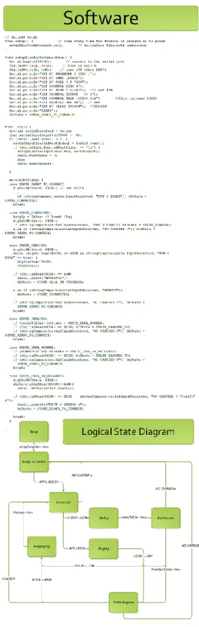
We discovered that our original Arduino board and Bluetooth shield would be inadequate for our project because the Bluetooth shield did not support the Hands Free or Headset profiles, so we purchased another board. We created a state diagram for the programming, representing the calling process for a phone. We wrote code that successfully pairs our device to a cell phone using the Hands Free profile, so the cell phone recognizes our device as a standard Bluetooth headset. We are able to answer calls from our device, as well as hang up active calls, and we are able to output tones to computer speaker to simulate a ringtone on an incoming call.
2.2 Current Status
As of May 2013, we have accomplished a significant amount of our project. Our device automatically starts in “pairing” mode using the Hands Free Profile. This mode starts when the device is connected to AC power, and waits for a phone to pair and connect. After the phone connects, our device waits for either an incoming call or for the “hook” signal to change, indicating the user wants to dial a number. Upon receiving an incoming call, we are able to play a ringtone through computer speakers, and we have the option to answer the call via the hook switch, simulating a user picking up a landline phone.
Unfortunately, we were not able to completely finish the project. We have our device able to pair with a cell phone using the Hands Free profile, and we are able to answer and hang up calls from our device. We are able to detect and answer incoming calls, but we are not able to transmit audio. We suspect that a large problem is the lack of processing power on the Arduino device, as well as its lack of analog-to-digital converters.
2.3 Plans for Continuation
We recommend that the project be continued next semester. After all of the research that was dedicated to the project, another team would have resources available to redesign it from the ground up. If we had more time, we would use a more powerful development board than the Arduino, perhaps a Raspberry Pi, so that the audio could be processed better. Also, we encountered many problems with the ringer hardware, stepping up the 5V signal to 115 VAC. We would consider using transformers in the future, to save time and efficiently step up the voltage.
9
There are also several features that could be added to the system, such as text-to-speech capabilities for an Android app, so that SMS text messages could be translated to an audio signal and read to the user, and allowing the user to dictate a reply message to be sent out. A future team could also add the ability to pair multiple phones with the device, and allow for different ring patterns to be used for each phone.
2.4 Budget
The budget for the project can be seen in Appendix B.
Chapter 3 Technical Aspects
The main topics that are covered in this project are Bluetooth specifications and implementation, Arduino coding and logic, analog signal amplifiers, and American landline telephone services.
3.1 Bluetooth
Bluetooth is a wireless technology for short range communication to replace cables that would connect portable and fixed-position electronic devices. The main features of Bluetooth are its low power draw, implementation ease, and application. According to the official Bluetooth SIG [3], the Bluetooth specification comes in two forms: Basic Rate (BR) and Low Energy (LE). Our focus is on the BR which includes the Enhanced Data Rate (EDR) extension. The EDR boosts transmission speed from 721.2 kbps to 2.1 Mbps which will be able to handle voice transmission.
Bluetooth operates in the Industrial Scientific and Medical (ISM) band at 2.4 GHz and employs frequency hopping to reduce interference. The frequency hopping is divided into 79 1 MHz blocks between 2.402 and 2.480 GHz and the radio switches at a rate of 1,600 per second and is controlled by a common clock.
When devices sense each other, the two radios communicate to attempt to connect although true connection requires the user to enter a passkey based on the Simple Secure Pairing (SSP) aspect of the second revision of the Bluetooth specification (Bluetooth 2.0). After pairing the 2 or more devices are classified as a Personal Area Network (PAN) or piconet. When devices are connected to the piconet, they are done in an ad-hoc manner and can take four positions: master, slave, parked, and standby. The purpose for the master and slave roles is to coordinate the clock for frequency hopping and to assign times when each device is to transmit or receive from the master. The parked position is for when there are more than seven active devices as this is the limit of devices for a master to be actively connected to. After there are 7 devices active, then next 255 devices to be connected will be parked, or inactive, and the master can activate the parked device at any time. The last position is standby which is default for all devices. The
10
standby mode is a low power mode and is not connected to “any piconet but listens for messages every 1.28 seconds over 32 hop frequencies” [4]
Figure 2: Example of Bluetooth piconets [3]
Bluetooth implements a modified version of the OSI Model [4]. As seen the figure below, the Bluetooth core protocols cover up to the Datalink layer of the OSI model and lets the applications handle processing the packets and presentation.
11
Bluetooth is special in that it uses profiles to carry out specific tasks. These profiles can be layered to pass functionality without having to encode each profile with redundant features. The Bluetooth Profiles define the required functions and features each layer (RF to RFCOMM/SDP) and how those layers interact from peer to peer. The Generic Access Profile (GAP) defines the basic requirements for a BT device depending on the mode of operation (BR or LE). In addition to the GAP, our device uses the Serial Port Profile (SPP) and the Headset Profile (HSP). The SPP generates a transport protocol for data by implementing a serial port emulator [3]. The Headset Profile inherits this emulated port from the SPP and adds a layer for converting voice to BT and adding features such as volume control, call answering, hang up, and voice dial.
We encountered a problem with the Bluetooth shield that was purchased from Seeed Studio. Its firmware did not support the Headset profile (HSP) or Hands Free profile (HFP), so from a hardware level, the shield would not fit our application. We later purchased another product which supports BlueGiga’s iWRAP protocol, which supports 13 Bluetooth profiles, including the two that pertain to the project [XX].
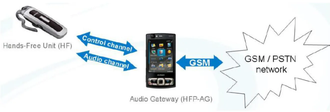
We chose to use the Hands Free profile (HFP) over HSP because of its added features. HFP supports higher quality audio- 8-bit, 16 KHz vs. 8 KHz audio. HFP also allows for features such as voice dialing. The most typical setup for an HFP system is shown below in Figure 4.
Figure 4: Hands-Free Profile Operation
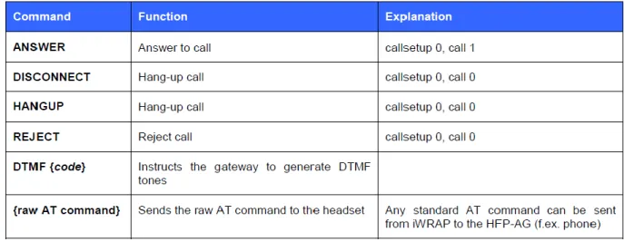
The iWRAP protocol supports AT commands to set different profiles and perform basic functions. Shown in Table 1 are the HFP commands that are able to be sent from the HFU to the HFP-AG. There are dozens of commands available to send the other direction, not listed
12
below. The commands are sent via an established control channel, which is set up between the Hands-Free Unit and the Audio Gateway. These are the commands that we used in our program.
Table 1: AT Commands
3.2 Arduino
When selecting a development board, we chose the Arduino because of its extensive community support, as well as its relatively simple programming language. The Arduino code is all written in a C-based language, which Chris is familiar with. A typical Arduino program has a setup stage and a loop stage. The setup stage runs immediately after the unit receives power, and the run stage loops continuously, allowing us to power the unit with an AC adapter rather than via a USB port. We also needed something that was compatible with an array of add-on hardware, such as the Bluetooth module.
The most recent version of the Arduino development board is the model called the Arduino Uno R3 [5]. The board provides such features as 14 pins used for input or output, giving us plenty of room to expand and utilize features such as the Bluetooth shield and the RJ-11 breakout board. The Uno also provides six PWM pins, which will be used to transmit analog signal to the landline phone.
A sample code which we modified can be found in Appendix F. The setup and loop stages are clearly defined. The program begins by defining pins to use as transmit and receive, since Bluetooth data transfer is serial and requires one input and one output line. In the setup stage, the baud rate is set and the pins are initialized, then the Bluetooth connection is established in SPP mode. During the loop stage, a variable is created as a buffer to store a character, then
13
the program checks to see if data is being received from the Bluetooth antenna. If so, it prints the received characters; otherwise it checks to see if data is ready to be sent. After individual characters are printed, the loop is broken, and it goes back to checking to see if there is any incoming or outgoing data waiting to be handled.
Our most recent code is shown in Appendix F. The code sets our device as Hands-Free Unit (HFU) in the Hands Free profile, which causes a cell phone to recognize the device as a Bluetooth headset. The loop in the code is set up similarly to the state diagram we created, with a switch statement containing a case for each state in the diagram. The states are transitioned by outside events, such as a “hook” switch, which represents a landline phone being physically picked up off the hook or hung up back onto the hook. The code also is set up to light different LEDs representing each state, so it can be clearly seen which part of the program is currently active. This system allows for setup and secure pairing of the device over Bluetooth, and incoming calls are processed and an artificial ringtone is generated. While the phone is ringing, if the landline is picked up off the hook, the device calls the command to answer the call, and the call is connected. When the landline phone is hung up and the hook switches back, the device sends the command to end the call, and the cell phone hangs up. The code also allows the system to enter a “dialing” state if the landline phone is picked up and there is no incoming call. Unfortunately, the code does not allow for voice signals to be transmitted, because the Arduino does not have sufficient A-D converters.
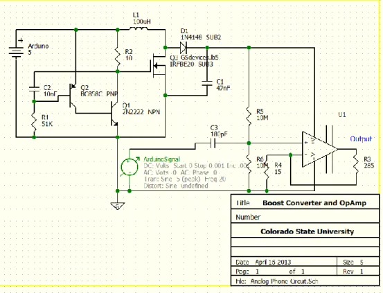
3.3 Amplifier
The output from the Arduino board is all digital outputs. Fortunately converting the digital signal to an analog AC signal is possible using Pulse-Width Modulation (PWM). There are 6 PWM pins on the Arduino allow us to simulate an analog signal. To amplify the signal we first need to build a circuit to boost the 5V DC to 115V DC. This is done with a boost converter.
The boost converter uses a variation of a ‘tank’ circuit. A regular tank circuit is a harmonic oscillator. Our boost converter uses a diode and power MOSFET to interrupt the return oscillation and instead, dump excess charge onto the capacitor, since the voltage on the capacitor is equal to the charge divided by its capacitance. So by sending charge from the inductor, across the diode, we are depositing charge onto the capacitor without it being fed back to the inductor because our diode blocks it. With this circuit, we are able to amplify the 5V DC signal to 115V DC.
We used the high voltage coming from the boost converter, to supply our high voltage Op Amp. We also used a voltage divider and a decoupling capacitor to bias the PWM signal from the Arduino. We are doing this to get a full swing on the output because we are driving the Op
14
Amp from ground to 115V DC. This means our bias point has to be at 62.5V so we can have a full signal swing on the output.
In theory this configuration would lead to a successful ring on the phone. This configuration led to many problems. Since we are using a high voltage signal and are severely limited on current (40mA) we needed to use very high impedances to keep the output voltage stable. This led to another problem because the impedance between the positive and negative supply terminals on the Op Amp measured at 24 Ohms. Since this impedance was so low, it drew all available current away from the capacitor and essentially grounded the output voltage of the boost converter.
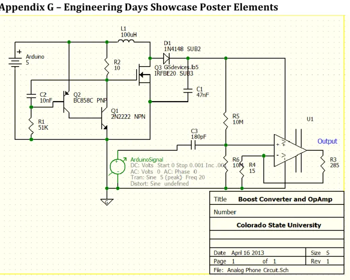
Figure 5: Analog Circuit 3.4 Landline Phones
Landline phones operate on the Public Switched Telephone Network (PSTN). This network consists of telephone lines, fiber optic cables, cellular networks, communication satellites, and undersea cables to enable communication with any other phone in the world. This network has been undergoing changes since it was created but the biggest move was from analog to digital systems. Now all the back end operation is controlled digitally but still calls are delivered as an analog signal. When a call is made, the digital systems convert the analog call using 8-bit resolution at 8 kHz using nonlinear pulse code modulation as per the standard G.711 from ITU-T. In the United States, landline phones operate on a 90V sine wave at a -48V DC
15
bias. The -48V bias is to run the ringer for analog phones since the PSTN provided power to phones so calls could still be made even if the power in the home went out [6].
Modern phones use Dual-Tone Multi-Frequency (DTMF) signaling for placing calls. This system works by mixing two sine waves. The frequency of the sine waves is dependent on the button being pushed. The table below shows the coloration between the mix of frequencies and what button it represents.
1209 Hz 1336 Hz 1477 Hz 1633 Hz
697 Hz 1 2 3 A
770 Hz 4 5 6 B
852 Hz 7 8 9 C
941 Hz * 0 # D
Table 2: DTMF Table showing relation between tones and number pressed [6]
By mixing these two frequencies one signal can be sent to the switching center which uses a demultiplexer to analyze what button was pushed and rout the call to the correct place. In addition to these tones, there are also dual tones for the dial tone (350 and 440 Hz), ring back tone (440 and 480 Hz), and busy signal (480 and 620 Hz).
Chapter 4 - Testing
Our original plans were to develop the hardware and software components separately, test them individually then integrate the two components. During the development we communicated what the hardware and software sides needed so that we would have minimal errors after integration.
The software aspect of the project called for incremental testing and development, to test features as soon as they could be realized. First we tested the Serial Port Profile (SPP) because the Handset and Hands-Free profiles are subsets of the SPP, and we wanted the simplest connection for initial Bluetooth testing. We were able to program the Arduino to broadcast as a simple Bluetooth device, then using an Android app called Bluetooth SPP, we were able to connect to the Arduino and send text-based messages between the phone and Arduino. With this system, we were able to use the phone’s screen as well as a terminal window on a PC to see messages and relevant information that was being sent and received, which immensely helped for debugging.
16
To further the project, we needed to move into HFP, which was not supported by the Bluetooth shield’s firmware, so we had to change the board to avoid rewriting firmware. The new board which supported HFP does not have a USB port to directly connect to a PC, so all software updates are transmitted via Bluetooth SPP to the board. We discovered that the Bluetooth module on the board closed the SPP connection with the host PC when the profile was switched to HFP. Therefore, we were unable to use the on-screen terminal to debug the information being transmitted over the Bluetooth device. We used reference manuals to infer which commands should be sent and received between the board, which acted as our HFU and the phone, which acted as the HFP-AG. We used LED’s on the outputs of the Arduino board to decipher if certain commands were passed, received, and interpreted correctly. We were able to see exactly when the phone paired, and when the software arrived at the various states in the state diagram.
On the Hardware side, we tested in stages, similarly to the software side. First I tested the boost converter circuit, this was to ensure the boost converter was outputting a sufficient voltage to ring the phone. Since it was, we tried applying an AC signal to it but found that the boost converter does not operate with an AC supply. This changed the design and is the reason why we needed the Op Amp. Fortunately we were able to use the boost converter circuit to drive the supply of the Op Amp. To get the correct signal swing, biasing was needed through the voltage divider and decoupling capacitor. The problem that we encountered was when the Op Amp was added to the circuit. This was because the impedance between the positive and negative supply terminals was much less that the impedance of the voltage divider. As explained in the hardware section, the boost converter was not able to supply enough current to keep the voltage at a sustainable level.
Since we were unable to complete the ringer circuit, we were unable to integrate the components to a working device. Although if we were able to integrate, we would have started simple with the testing and evaluate each state the Arduino was in to verify that the data we were imputing functioned in the way we wanted it to, such as making sure the phone doesn’t dial out when you are in a call.
Chapter 5: Challenges
Note: Although business aspects towards commercializing this product are discussed there are no plans on building this device for commercial use.
5.1 Legal
During the inception of this project there were concerns that we would be violating service contracts from cellular service providers and landline service providers. We looked through contracts from Verizon in regards to their cellular contract and found no information that
17
would jeopardize the project. We also looked to the product side for a proof-of-concept with existing hands free devices such as wireless headsets. Our project operates on the same principle just changing the receiver from a headset to a home phone. After we came up with the project we found devices that operated under the same principle as our device where you would connect your phone wirelessly and it would forward calls to the house phone.
5.2: Manufacturability
This device is designed for the common consumer which means that to build this product commercially, we would need to put a high focus on building this device so we could price it competitively in the market. Based on the current parts list and complexity in design, our device would not be able to be manufactured cheaply or easily. However, prototyping and design is normally much more expensive than manufacturing. After we have a working proof of concept model, we would be able to focus on consolidating parts, boards, and software to make the manufacturing process much more efficient. With this approach, we would be able to manufacture the device efficiently.
5.3: Marketability
With over 132 million housing units in 2011 in the United States (US Census), and a rapid growth in cell phone-only households in the US (5x increase in 6 years) there would be a market of at least 33 million households just in the United States. As long as manufacturing costs could be kept down with methods discussed in the manufacturability section and using economy of scale, costs could be kept down to be priced competitively with other, similar products.
As discussed in the Introduction, people are searching for alternatives to standard landline service. This brings VoIP services into the equation and as discussed earlier, our device has much better security and does not have a monthly charge. This in addition to our modular approach makes our device desired by consumers and would be receptive to marketing about our product.
5.4: Sustainability
To make our product a success on the market, we would need to enact support systems, guarantee statements, and a supply chain to ensure quality of service, speedy delivery, and consumer satisfaction. To ensure the long term success of this product, consumer satisfaction would need to be the top priority. To do this, we need to keep the customers’ needs first and ensure we are meeting and exceeding their standards. This is essential because we do not have funding for mass-marketing which means we would need to sell based on word-of-mouth marketing and referrals.
18
There are no health and safety concerns with this product as it is a low power device that will rarely be close enough to the user to cause any health concerns. Since the device is designed to remain in one place and is lightweight, there are no safety concerns for handling the device.
Chapter 6 - Conclusion
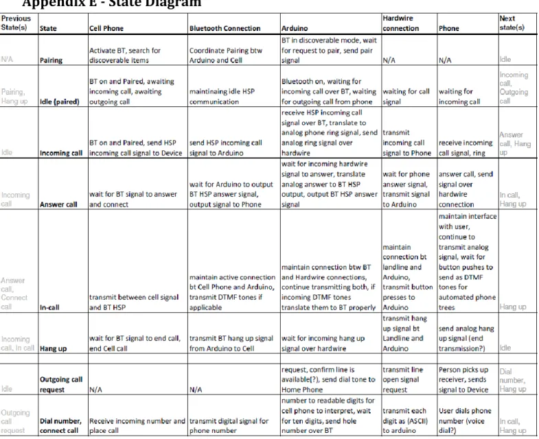
Based on the discussion above, we believe that this project will work and that we will be able to deliver by Engineering Days in the spring of 2013. As discussed in Chapter 2.3, we still need to finish designing and build the amplifier circuit. On the software side, we need to develop the Arduino code based on the state table of Appendix E. Lastly we need to implement the testing plan that is currently being designed. This step will include a phased approach with regression testing to ensure all functions and features will work when the testing is complete.
19
References
[1] Blumberg SJ, Luke JV. Wireless substitution: Early release of estimates from the National Health Interview Survey, January–June 2011. National Center for Health Statistics. December 2011. Available from: http://www.cdc.gov/nchs/nhis.htm. [2] Vaishnav, Chintan and Fine, Charles H., A Dynamic Assessment of VoIP Adoption,
Innovation and their Interaction with CALEA Regulation (August 15, 2006). TPRC 2006. Available at http://ssrn.com/abstract=2119747
[3] Specification of the Bluetooth System, v 4.0, vol 1, Bluetooth Special Interest Group, Kirkland, WA, 2010.
[4] C.S.R. Prabhu, Bluetooth: Technology and Its Applications with Java and J2ME, New Delhi: PHI Learning, Ltd. 2006, pp 43-45.
[5] Arduino Uno Specifications, Arduino, 2012, Available at http://www.arduino.cc/en/Main/arduinoBoardUno [6] WiseGeek.org, What are DTMF Tones?, Available at
20
Appendix A - Abbreviations
A2DP – Advanced Audio Distribution Profile
AC – Alternating Current BR – Basic Rate
CSU – Colorado State University DC – Direct Current
DTMF – Dual-Tone Multi-Frequency ECE – Electrical and Computer Engineering EDR – Enhanced Data Rate
FCC – Federal Communication Commission HSP – Headset Profile
HFP – Hands-Free Profile
IEEE - Institute of Electrical and Electronics Engineers
ITU-T – ITU Telecommunication Standardization Sector
LE – Low Energy
OSI – Open Systems Interconnection PAN – Personal Area Network
PSTN – Public Switched Telephone Network PWM – Pulse Width Modulation
RF – Radio Frequency
RFCOMM – Radio Frequency Communication SDP – Service Directory Protocol
SMS – Simple Message
21
SSP – Simple Secure Pairing USB – Universal Serial Bus
22
Appendix B - Budget
Our budget for this project began with $300 from the ECE department at CSU. Of this, $200 was issued as a standard two person team for the Senior Design program. The remaining $100 was issued for creating the project idea on our own.
We later applied for, and subsequently received, an undergraduate research grant from the IEEE. The grant provided us with an additional $500. One condition for the grant was to write an IEEE-styled paper at the end of April and submit it to the IEEE.
We also received a sponsorship from Agilent which gave us an additional $500 for our project.
We have spent a total of $396.09. With this we had $903.91 left in our budget after the Engineering Showcase. The expenditures are outlined below:
Vendor Description Price
Amazon.com Arduino Uno R3 21.95
NKC Electronics, Inc. Power Adapter for Arduino (generic) - 9v DC, 650 mA
6.75
Aerospace Robotics, LLC Seeed Studio Bluetooth Shield 29.95
Iron Electronics RJ-11 Breakout Board (generic) 8.00
Miami Electronics Breadboard (generic) 2.60
Tiger Direct OSEPP BTH-01 Arduino Bluetooth 99.99
Jameco Assorted Components 50.49
DigiKey Adapter Boards 23.85
Newegg AT&T Corded Phone x2 62.91
Best Buy USB Bluetooth Adapter 20
Walmart Speaker 18.88
Walmart Power Supply 14.96
Walmart 3.5mm audio cable 9.88
Danny Szczotka Landline Phone Donated
Danny Szczotka Motorola Droid X Smartphone Borrowed
Chris Switzer Samsung Galaxy SIII Smartphone Borrowed
Danny Szczotka Misc. simple components Donated
Shipping 17.42
23
Appendix C – Timeline
24
Appendix D - Test Plan
Since cell phones have become a necessity for billions of people all over the world, we have grown to depend on the seemingly endless levels of mobility and flexibility they provide. With the current state of the economy, people have been forced to cut expensive unnecessary services, and cell phone owners are realizing that they don’t need to pay for and maintain a redundant landline telephone service. In recent years, we have seen the growth of VoIP (Voice over IP) as a cheaper alternative to home phone service. Security has been a fatal flaw in this technology, since voice is transmitted over the Internet with little to no encryption. This problem has sparked our interest to provide a viable alternative to leverage the benefits of landline and cellular phone services.
We will create a device that links home phone systems to cell phones, in order to reduce monthly costs for the average consumer. When the user receives a call on their cell phone, our device will ring all of the existing landline phones in their home, maintaining the convenience of having a phone in every room. We plan to retain as much functionality as possible: we want to be able to send and receive calls and SMS messages seamlessly. Our device will also allow consumers to charge their phones and keep them in a spot in their home with known good cellular reception.
The goal of building this device is to integrate preexisting home phone networks with the highly mobile cell phones to allow people the capability to have the convenience of a home phone system without having to pay the monthly fee for a landline service, as well as to remove the security concerns with VoIP services. We plan to have a working prototype by mid-April 2013 before Engineering Days, where we will be presenting our project. The prototype will be able to transmit calls and voice to the home phone network, as well as be able to conduct simple text messages. In order to achieve these goals, we have several components that need to be able to work together harmoniously. We’ll need to test the system at various points during its
construction to ensure that we stay on the right track. At each stage, we’ll perform each test leading up to that stage as well, in order to make sure all features still work.
Our first milestone we hope to accomplish is to assemble the Arduino and Bluetooth shield, and to program the Arduino to operate with the Bluetooth HSP protocol. We will be able to test this by “pairing” a cell phone with our device. At this stage, the phone should be able to recognize the Bluetooth device, but it should error out while pairing, since the hardware won’t be programmed to do anything else with the Bluetooth data. If we are unable to pair the phone, we’ll need to confirm that the program we write on the Arduino will properly assign the
Bluetooth shield to operate in HSP mode. If the Arduino produces no errors when programming the Bluetooth module, we’ll try to pair it with a different phone, and if that doesn’t work we’ll swap out Bluetooth modules.
25
Once we have successfully paired the phone and the device, the next step is to program the Arduino to convert the Bluetooth signal into an analog signal recognized by a landline telephone. We will start by connecting simple ear bud-style headphones to the device, rather than a landline phone, to simplify the connection and confirm that we are properly interpreting the Bluetooth signal. At this stage, we should be able to hear audio from the headphones when we speak into the connected cell phone. If it doesn’t work, we’ll begin to try to slowly amplify the signal. If we can’t hear audio at all, we’ll continue to amplify the signal. If we’ve reached the maximum level that we can amplify the output signal, we’ll have to start looking into using an external hardware-level amplifier.
Once we can hear incoming sound, we’ll connect our basic landline phone, and attempt to hear incoming calls. We suspect that we’ll need to amplify the call volume more for a landline phone than we will for the low-powered headphones. We’ll follow the same steps as the headphone-level testing: slowly amplifying the signal until we can hear incoming sound.
After we have incoming sound, we’ll have to open a return channel, to transmit voice back across an analog to digital converter, converted back to Bluetooth packets, and transmitted back to the cell phone. If we can’t send and receive sound through to the landline phone, we’ll need to troubleshoot all of the connections and confirm that the Bluetooth connection is still paired with the phone. The Arduino program should be producing debugging information at this point, and so we should be able to confirm that both incoming and outgoing Bluetooth channels are open and conducting.
After we can send and receive voice calls, we’ll have to look into ways to make the landline phone ring upon an incoming call. We aren’t sure how the Bluetooth HSP standard handles it- we’ve found conflicting reports about it in our research. This stage will likely require a lot of trial and error style troubleshooting. We suspect that we’ll have to use an oscilloscope to measure the standard incoming ring produced by the connected cell phone, and alter the signal from there. We may have to use that incoming signal to trigger our hardware to produce a signal which will cause the landline phone to ring.
When we can receive incoming calls, we’ll have to figure out how to program the Arduino to pass through outgoing calls as well. Picking up the landline phone (or pressing the “send” button) will need to trigger the Arduino to prepare to make a call. We’ll need to
configure the Arduino to interpret the numbers on the keypad of the phone to digital signals that can be interpreted by the cell phone as numbers it can use to dial a phone number. This will bypass the HSP protocol in Bluetooth and will require a separate data channel using a different protocol.
This is how far we hope to get with the project. If we finish the above stages early, we’ll attempt to add a text messaging feature to our device. That will require writing an Android app
26
to interpret the text messages as some sort of data stream, which we will process through the Arduino, and somehow send that data stream to the landline phone. This will likely not be supported by our Bluetooth system, since the OS of the phone will see our device as a headset. This will require a significant amount of additional planning and testing. We ordered the necessary hardware to perform this function, but we know so little about Wi-Fi streams coming from Android apps and being interpreted into something similar to a landline phone’s caller ID, that we are focusing on the basic operation of our device first, and if all goes well we can implement and test the text messaging feature.
At this point, we’ll have a complete system to test. We’ll make sure we can answer calls by picking up the phone, as well as end calls by hanging up the phone. It’s also important that we test scenarios such that while in a call, and another incoming call occurs, the system properly handles it. Also, we need to make sure the Bluetooth data streams are not closed completely at the call’s end so that the device remains paired with the cell phone. We’ll need to test how the phone handles an incoming call near the time of an outgoing call.
27
Appendix E - State Diagram
28
Appendix F - Arduino Code
#include <SoftwareSerial.h> //Software Serial Port #include <Tone.h> // for the ringtone
#define RxD 0 // Arduino Tx and Rx pins #define TxD 1 // int toner = 10; // char serialInput[100]; #define STATE_SETUP 0 #define STATE_READY_TO_CONNECT 1 #define STATE_CONNECTED 2 #define STATE_RINGING 3 #define STATE_CALL_IN_PROGRESS 7 #define STATE_HANGING_UP 8 int serialNextIndex = 0; int btState = 0;
bool setupComplete = false; #define HOOK 12
bool callAnswered = false; bool readyToDial = false; bool numberDialed = false; bool hungUp = false; #define a 9 #define b 2 #define c 3 #define d 4 #define e 5 #define f 6 #define g 8 String command = "";
void setup() { // runs every time the Arduino is plugged in to power
pinMode(RxD, INPUT); // set Receive pin to input
pinMode(TxD, OUTPUT); // set Transmit pin to output
pinMode(a,OUTPUT); pinMode(b,OUTPUT); pinMode(c,OUTPUT); pinMode(d,OUTPUT); pinMode(e,OUTPUT); pinMode(f,OUTPUT); pinMode(g,OUTPUT); pinMode(HOOK,INPUT);
setupBlueToothConnection(); // initialize Bluetooth connection
}
void setupBlueToothConnection() {
Serial.begin(115200); // connect to the serial port digitalWrite(a, HIGH);
digitalWrite(b, LOW); digitalWrite(c, LOW); digitalWrite(d, LOW); digitalWrite(e, LOW);
29 digitalWrite(f, LOW);
digitalWrite(g, LOW); delay(2000);
Serial.println("SET BT PAGEMODE 3 2000 1"); Serial.println("SET BT NAME LINKER"); Serial.println("SET BT ROLE 0 f 7d00"); Serial.println("SET CONTROL ECHO 0"); Serial.println("SET BT AUTH * 12345"); Serial.println("SET CONTROL ESCAPE - 00 1");
Serial.println("SET CONTROL BAUD 115200,8n1"); //first release 19200 Serial.println("SET PROFILE HFP ON"); // HFP
Serial.println("SET BT CLASS 200404"); //200404 Serial.println("RESET"); btState = STATE_READY_TO_CONNECT; setupComplete = true; } void playTone(){ tone(toner, 4800, 500); delay(1000); } void ringtone() { tone(toner, 500, 200); delay(200); tone(toner, 1000, 200); delay(200); tone(toner, 1500, 200); delay(200); tone(toner, 2000, 200); delay(200); tone(toner, 2500, 200); delay(200); tone(toner, 3000, 200); delay(200); tone(toner, 3500, 200); delay(200); tone(toner, 4000, 200); delay(200); } void loop() {
boolean serialReceived = false; char serialInputReceived[100] = { 0 }; if (Serial.available() > 0){ serialInput[serialNextIndex] = Serial.read(); if (serialInput[serialNextIndex] == '\n') { strcpy(serialInputReceived, serialInput); serialNextIndex = 0; } else {
30 serialNextIndex++; } } case STATE_READY_TO_CONNECT: // No action, wait
hungUp = false; // Reset flag digitalWrite(a, LOW); digitalWrite(b, HIGH); digitalWrite(c, LOW); digitalWrite(d, LOW); digitalWrite(e, LOW); digitalWrite(f, LOW); digitalWrite(g, LOW);
if (stringCompare(serialInputReceived, "HFP 0 READY")) btState = STATE_CONNECTED; break;
case STATE_CONNECTED:
hungUp = false; // Reset flag digitalWrite(a, LOW); digitalWrite(b, LOW); digitalWrite(c, HIGH); digitalWrite(d, LOW); digitalWrite(e, LOW); digitalWrite(f, LOW); digitalWrite(g, LOW);
if (stringCompare(serialInputReceived, "HFP 0 RING")) btState = STATE_RINGING; else if (digitalRead(HOOK) == LOW) btState = STATE_DIALING;
else if (stringCompare(serialInputReceived, "NO CARRIER 0")) btState = STATE_READY_TO_CONNECT; break; case STATE_RINGING: digitalWrite(a, LOW); digitalWrite(b, LOW); digitalWrite(c, LOW); digitalWrite(d, HIGH); digitalWrite(e, LOW); digitalWrite(f, LOW); digitalWrite(g, LOW); time = 0;
while (digitalRead(HOOK) == HIGH && stringCompare(serialInputReceived, "HFP 0 RING")== true){ // time++; digitalRead(HOOK); ringtone(); } if (digitalRead(HOOK) == LOW) { Serial.print("ANSWER\n"); callAnswered = true; btState = STATE_CALL_IN_PROGRESS; }
else if (stringCompare(serialInputReceived, "HANGUP")){ btState = STATE_CONNECTED;
}
if (stringCompare(serialInputReceived, "NO CARRIER 0")) btState = STATE_READY_TO_CONNECT;
31 case STATE_DIAL_NUMBER:
if (numberDialed) btState = STATE_CALL_IN_PROGRESS;
if (digitalRead(HOOK) == HIGH) btState = STATE_HANGING_UP; if (stringCompare(serialInputReceived, "NO CARRIER 0")) btState = STATE_READY_TO_CONNECT;
break;
case STATE_CALL_IN_PROGRESS: // No action, wait
numberDialed = false; // Reset flag callAnswered = false; // Reset flag digitalWrite(a, LOW); digitalWrite(b, LOW); digitalWrite(c, LOW); digitalWrite(d, LOW); digitalWrite(e, HIGH); digitalWrite(f, LOW); digitalWrite(g, LOW); while(digitalRead(HOOK)==LOW){ Serial.write(Serial.read()); }
if (digitalRead(HOOK) == HIGH || stringCompare(serialInputReceived, "NO CARRIER 0 \"call\" 0")) { // btState = STATE_HANGING_UP; Serial.println("HPFP 0 STATUS n"); btState = STATE_READY_TO_CONNECT; } break; default: btState = STATE_READY_TO_CONNECT; break; }
strcpy (serialInputReceived, '\0'); // Only evaluate serialInputReceived once }
boolean stringCompare(char* string1, char *string2) {
int stringIndex = 0;
for (int i =0; i<strlen(string2);i++)
if (string2[i] != '?') // Add wildcard functionality if (string1[i] != string2[i]) return false;
return true; }
Code Used for E Days Demo:
#include <SoftwareSerial.h> //Software Serial Port
#define RxD 0 // Arduino Tx and Rx pins as labeled on board
#define TxD 1
SoftwareSerial blueToothSerial(RxD,TxD);
32
Serial.begin(9600); // set baud rate
pinMode(RxD, INPUT); // set Receive pin to input
pinMode(TxD, OUTPUT); // set Transmit pin to output
setupBlueToothConnection(); // initialize Bluetooth connection
}
void loop() { // runs continuously after startup
char recvChar; // temp variable to buffer a received character
while(1){ // runs forever
if(blueToothSerial.available()){ //check if data sent from Bluetooth shield
recvChar = blueToothSerial.read(); // if so, buffer the character
Serial. Print(recvChar); // print the buffered character to the terminal
if(!blueToothSerial.available()){ // if there’s no more incoming data
Serial.print("\n"); // .. print a new line to
clean up } }
if(Serial.available()){//check if data sent from the local serial terminal recvChar = Serial.read(); // if so, buffer the outgoing character blueToothSerial.print(recvChar); // send the buffered character out to BT
Serial.print(recvChar); // print the buffered character to terminal
delay(10); // wait 10 ms, to allow the character to send
if(!Serial.available()){ // if there’s nothing left to send
Serial.print("\n"); // .. print a new line to clean up
blueToothSerial.print("\n"); // send a new line over BT as well } } } } void setupBlueToothConnection() {
blueToothSerial.begin(38400); //Set Bluetooth BaudRate to default (38400) blueToothSerial.print("\r\n+STWMOD=0\r\n"); //set the Bluetooth to slave mode delay(2000); // This delay is required.
blueToothSerial.print("\r\n+INQ=1\r\n"); //make the slave Bluetooth inquirable Serial.println("The slave Bluetooth is inquirable!");
delay(2000); // This delay is required. blueToothSerial.flush();
34 void setupBlueToothConnection() {
Serial.begin(115200); // connect to the serial port digitalWrite(a, HIGH); // turn on LLED A
digitalWrite(b, LOW); // turn off other LED's Serial.println("SET BT PAGEMODE 3 2000 1"); Serial.println("SET BT NAME LINKER"); Serial.println("SET BT ROLE 0 f 7d00"); Serial.println("SET CONTROL ECHO 0");
Serial.println("SET BT AUTH * 12345"); // set PIN Serial.println("SET CONTROL ESCAPE - 00 1");
Serial.println("SET CONTROL BAUD 115200,8n1"); //first release 19200 Serial.println("SET PROFILE HFP ON"); // HFP
Serial.println("SET BT CLASS 200404"); //200404 Serial.println("RESET");
}
#include <SoftwareSerial.h> //Software Serial Port #include <Tone.h> // for the ringtone
#define RxD 0 // Arduino Tx and Rx pins #define TxD 1 // int toner = 10; // char serialInput[100]; #define STATE_SETUP 0 #define STATE_READY_TO_CONNECT 1 #define STATE_CONNECTED 2 #define STATE_RINGING 3 #define STATE_CALL_IN_PROGRESS 7 #define STATE_HANGING_UP 8 int serialNextIndex = 0; int btState = 0;
bool setupComplete = false; #define HOOK 12
bool callAnswered = false; bool readyToDial = false; bool numberDialed = false; bool hungUp = false; #define a 9 #define b 2 #define c 3 #define d 4 #define e 5 #define f 6 #define g 8 String command = "";
void setup() { // runs every time the Arduino is plugged in to power
pinMode(RxD, INPUT); // set Receive pin to input
pinMode(TxD, OUTPUT); // set Transmit pin to output
pinMode(a,OUTPUT); pinMode(b,OUTPUT); pinMode(c,OUTPUT);
35 pinMode(d,OUTPUT); pinMode(e,OUTPUT); pinMode(f,OUTPUT); pinMode(g,OUTPUT); pinMode(HOOK,INPUT);
setupBlueToothConnection(); // initialize Bluetooth connection
}
void setupBlueToothConnection() {
Serial.begin(115200); // connect to the serial port digitalWrite(a, HIGH); digitalWrite(b, LOW); digitalWrite(c, LOW); digitalWrite(d, LOW); digitalWrite(e, LOW); digitalWrite(f, LOW); digitalWrite(g, LOW); delay(2000); Serial.println("SET BT PAGEMODE 3 2000 1"); Serial.println("SET BT NAME LINKER"); Serial.println("SET BT ROLE 0 f 7d00"); Serial.println("SET CONTROL ECHO 0"); Serial.println("SET BT AUTH * 12345"); Serial.println("SET CONTROL ESCAPE - 00 1");
Serial.println("SET CONTROL BAUD 115200,8n1"); //first release 19200 Serial.println("SET PROFILE HFP ON"); // HFP
Serial.println("SET BT CLASS 200404"); //200404 Serial.println("RESET"); btState = STATE_READY_TO_CONNECT; setupComplete = true; } void playTone(){ tone(toner, 4800, 500); delay(1000); } void ringtone() { tone(toner, 500, 200); delay(200); tone(toner, 1000, 200); delay(200); tone(toner, 1500, 200); delay(200); tone(toner, 2000, 200); delay(200); tone(toner, 2500, 200); delay(200); tone(toner, 3000, 200); delay(200); tone(toner, 3500, 200); delay(200); tone(toner, 4000, 200); delay(200); }
36 void loop()
{
boolean serialReceived = false; char serialInputReceived[100] = { 0 }; if (Serial.available() > 0){ serialInput[serialNextIndex] = Serial.read(); if (serialInput[serialNextIndex] == '\n') { strcpy(serialInputReceived, serialInput); serialNextIndex = 0; } else { serialNextIndex++; } } case STATE_READY_TO_CONNECT: // No action, wait
hungUp = false; // Reset flag digitalWrite(a, LOW); digitalWrite(b, HIGH); digitalWrite(c, LOW); digitalWrite(d, LOW); digitalWrite(e, LOW); digitalWrite(f, LOW); digitalWrite(g, LOW);
if (stringCompare(serialInputReceived, "HFP 0 READY")) btState = STATE_CONNECTED; break;
case STATE_CONNECTED:
hungUp = false; // Reset flag digitalWrite(a, LOW); digitalWrite(b, LOW); digitalWrite(c, HIGH); digitalWrite(d, LOW); digitalWrite(e, LOW); digitalWrite(f, LOW); digitalWrite(g, LOW);
if (stringCompare(serialInputReceived, "HFP 0 RING")) btState = STATE_RINGING; else if (digitalRead(HOOK) == LOW) btState = STATE_DIALING;
else if (stringCompare(serialInputReceived, "NO CARRIER 0")) btState = STATE_READY_TO_CONNECT; break; case STATE_RINGING: digitalWrite(a, LOW); digitalWrite(b, LOW); digitalWrite(c, LOW); digitalWrite(d, HIGH); digitalWrite(e, LOW); digitalWrite(f, LOW); digitalWrite(g, LOW); time = 0;
while (digitalRead(HOOK) == HIGH && stringCompare(serialInputReceived, "HFP 0 RING")== true){
37 // time++; digitalRead(HOOK); ringtone(); } if (digitalRead(HOOK) == LOW) { Serial.print("ANSWER\n"); callAnswered = true; btState = STATE_CALL_IN_PROGRESS; }
else if (stringCompare(serialInputReceived, "HANGUP")){ btState = STATE_CONNECTED;
}
if (stringCompare(serialInputReceived, "NO CARRIER 0")) btState = STATE_READY_TO_CONNECT;
break;
case STATE_DIAL_NUMBER:
if (numberDialed) btState = STATE_CALL_IN_PROGRESS;
if (digitalRead(HOOK) == HIGH) btState = STATE_HANGING_UP; if (stringCompare(serialInputReceived, "NO CARRIER 0")) btState = STATE_READY_TO_CONNECT;
break;
case STATE_CALL_IN_PROGRESS: // No action, wait
numberDialed = false; // Reset flag callAnswered = false; // Reset flag digitalWrite(a, LOW); digitalWrite(b, LOW); digitalWrite(c, LOW); digitalWrite(d, LOW); digitalWrite(e, HIGH); digitalWrite(f, LOW); digitalWrite(g, LOW); while(digitalRead(HOOK)==LOW){ Serial.write(Serial.read()); }
if (digitalRead(HOOK) == HIGH || stringCompare(serialInputReceived, "NO CARRIER 0 \"call\" 0")) { // btState = STATE_HANGING_UP; Serial.println("HPFP 0 STATUS n"); btState = STATE_READY_TO_CONNECT; } break; default: btState = STATE_READY_TO_CONNECT; break; }
strcpy (serialInputReceived, '\0'); // Only evaluate serialInputReceived once }
boolean stringCompare(char* string1, char *string2) {
38 for (int i =0; i<strlen(string2);i++)
if (string2[i] != '?') // Add wildcard functionality if (string1[i] != string2[i]) return false;
return true; }
39
Appendix G – Engineering Days Showcase Poster Elements
Figure 6: Analog Circuit Diagram
40
41
42
43
Appendix H – IEEE Grant Proposal Application
Since cell phones have become a necessity for billions of people all over the world, we have grown to depend on the seemingly endless levels of mobility and flexibility they
provide. With the current state of the economy, people have been forced to cut expensive unnecessary services, and cell phone owners are realizing that they don’t need to pay for and maintain a redundant landline telephone service. In recent years, we have seen the growth of VoIP (Voice over IP) as a cheaper alternative to home phone service. Security has been a fatal flaw in this technology, since voice is transmitted over the Internet with little to no
encryption. This problem has sparked our interest to provide a viable alternative to leverage the benefits of landline and cellular phone services.
We will create a device that links home phone systems to cell phones, in order to reduce monthly costs for the average consumer. Our device will allow consumers to charge their phones and keep them in a spot in their home with known good reception. We plan to retain as much functionality as possible: we want to be able to send and receive calls and SMS messages. When the user receives a call on their cell phone, all of the existing landline phones in their home will ring, maintaining the convenience of having a phone in every room.
We are considering using the IEEE 802.15, Bluetooth, standard because of its universal compatibility. Bluetooth capability has been a standard feature on cell phones for over a decade now, and we want people to be able to use our product regardless of their technical ability. To achieve this we will be further exploring the Headset Profile and Cordless Telephony profile. By using these profiles and their associated parent profiles, we should be able to build our device to accomplish calls and text messages.
We considered using the WiFi 802.11 standard as well. This would give us the added benefit of higher bandwidth for clearer call quality, and the ability to add other features, like notifications and transmission of SMS messages, e-mail, etc. However, this would limit our compatibility to smartphones, and eliminate functionality with standard cell phones.
The project is scheduled to conclude at the beginning of May 2013. Currently we are in the research phase, where we are learning about how Bluetooth and WiFi function and which standard would be the most beneficial and determining the hardware needed. After purchasing the hardware, we will move into the design and build phase where we will write the software and implement an iterative test plan. The final paper submission date is beyond 6 months from this application because our design project is a yearlong program with a final showing and
44
Appendix I - Acknowledgments
We would like to thank Professor Liuqing Yang for her ongoing support for the project. She has been an excellent source of information about wireless standards, as well as IEEE funding protocols
We would like to thank the IEEE (The Institute of Electrical and Electronics Engineers) for the undergraduate research grant. They provided us with $500, which will prevent us from using personal funds for this project.
We would also like to thank Bo Yu, for providing insight with programming the Arduino and developing the state diagram.
We would like to thank Professor Olivera Notaros, for organizing and moderating the Senior Design program for Electrical and Computer Engineering at Colorado State University. The presentations and information we have learned from the Senior Design program have encouraged us to pursue the idea for the project, and their initial funding of $300 has been extremely beneficial.
Lastly we would like to thank Agilent for sponsoring our project and giving us much appreciated help with the hardware design. In particular, we would like to thank Dan Ferguson and Mike Hawes.
![Figure 1: Graph of people with only wireless service with respect to time [1]](https://thumb-us.123doks.com/thumbv2/123dok_us/8718288.2360743/5.918.173.743.596.965/figure-graph-people-wireless-service-respect-time.webp)
![Figure 2: Example of Bluetooth piconets [3]](https://thumb-us.123doks.com/thumbv2/123dok_us/8718288.2360743/10.918.212.704.187.538/figure-example-of-bluetooth-piconets.webp)
![Table 2: DTMF Table showing relation between tones and number pressed [6]](https://thumb-us.123doks.com/thumbv2/123dok_us/8718288.2360743/15.918.200.718.329.522/table-dtmf-table-showing-relation-tones-number-pressed.webp)