$2.50
Air Dryer
Application
Guidelines
TP-9672
Revised 11- 98
• System Saver 1000 and 1200 Series
• System Saver TWIN
Table of Contents
Introduction
Purpose of This Guide . . . 1 Why a Vehicle Needs an Air Dryer
What a Desiccant-Type Air Dryer Does
Requirements and Installation
Choosing the Right Air Dryer for an Application: Single or TWIN Cartridge . . . 2 Meritor WABCO’s Single- and Dual-Cartridge Desiccant Air Dryers
System Saver 1000 and 1200 Series Single Cartridge System Saver TWIN Dual Cartridge
System Saver TWIN or a System Saver 1000 and 1200 Series
with a Bypass Line for Non-Brake Devices . . . 3 General Requirements Guidelines and Installation Criteria
Components
Air System Components Discussion . . . 8 Types of Air Compressor
Air Governor
Air Governor Signal Line . . . 9 Compressor Discharge Line
Air Dryer to Supply Tank Line Air System Reservoir Tanks
PCCV Placement
Pressure-Controlled Check Valve (PCCV) . . . 10 Determine the Correct Pressure-Controlled Check Valve (PCCV)
Placement for the System Saver 1000 and 1200 Series Air Dryer
Air Dryer Operating Parameters . . . 12
Regeneration Methods and Selection Factors
Desiccant Regeneration Methods . . . 13 Air Dryer Selection Factors
Flow Capacity Drying Capacity
Purge Air Volume . . . 14 Governor Range
Air Compressor Duty Cycle
Additional Information on
Meritor WABCO Air Dryers
• Maintenance Manual No. 34, System Saver 1000 and 1200 Series Air Dryers
• Installing the Meritor WABCO System Saver 1000 and 1200 Series Air Dryers (Publication TP-92116)
• Maintenance Manual No. 35, System Saver TWIN Air Dryer
• Installing theMeritor WABCO System Saver
How to Order
Order publications from Meritor Literature Distribution Center, c/o Vispac, Inc., 35000 Industrial Road, Livonia, MI 48150.
Introduction
Introduction
Purpose of This Guide
This Application Guide for Meritor WABCO’s System Saver Series and System Saver TWIN air dryers
r addresses air dryer selection and installation criteria for Meritor WABCO’s System Saver 1000 and 1200 Series and System Saver TWIN air dryers,
r discusses the air supply system,
r illustrates and describes system components and
r highlights features and benefits of the System Saver 1000 and 1200 Series and TWIN air dryers.
Why a Vehicle Needs an Air Dryer
r When air is compressed, the compressor takes in water vapor with the air, compresses the water vapor and puts it into the system as liquid water.
r Liquid water that accumulates in air lines can damage seals and valves, and wash away lubricants.
r In cold weather water can freeze, block air lines and damage air system components.
What a Desiccant-Type Air
Dryer Does
r Warm, humid air from the compressor condenses into either liquid water or water vapor before entering the air dryer.
r A desiccant-type air dryer protects a vehicle’s air brake system by drying moisture-laden air before it passes through the air reservoirs and into the brake system.
r Water collects in the base of the dryer when: — Warm air condenses into water before it
enters the dryer.
— Warm air condenses into water inside of the dryer before the water reaches the
desiccant.
r The desiccant material then removes additional water vapor, further drying the air.
r During the regeneration phase, the regeneration valve and pressure-controlled check valve remove water from the desiccant bed with a backflow of dried, expanded system air.
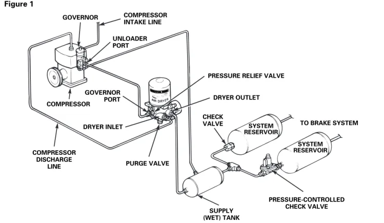
Figure 1 GOVERNOR COMPRESSOR INTAKE LINE UNLOADER PORT DRYER OUTLET CHECK
VALVE TO BRAKE SYSTEM
SYSTEM RESERVOIR SYSTEM RESERVOIR PRESSURE-CONTROLLED PURGE VALVE COMPRESSOR DISCHARGE LINE DRYER INLET COMPRESSOR GOVERNOR PORT
Requirements and Installation
Requirements and Installation
Choosing the Right Air Dryer
for an Application: Single or
TWIN Cartridge
Meritor WABCO’s Single- and
Dual-Cartridge Desiccant Air Dryers
System Saver 1000 and 1200 Series
Single-Cartridge Air Dryer
The System Saver 1000 and 1200 Series single-cartridge air dryer dries compressed air during the loaded cycle and regenerates (dries) the desiccant bed during the regeneration phase, which occurs when the compressor unloads.
System Saver TWIN Dual-Cartridge
Air Dryer
The System Saver TWIN dual-cartridge air dryer incorporates a solenoid valve that alternates incoming airflow between the two cartridges to simultaneously dry air in one cartridge and
regenerate the desiccant bed in the other cartridge.
NOTE: You cannot construct a dual-cartridge air dryer by plumbing together (in series or parallel) two System Saver 1000 and 1200 Series
single-cartridge air dryers. The System Saver TWIN air dryer’s dual-cartridges work by
simultaneously drying air in one cartridge and regenerating the desiccant bed in the other cartridge. This simultaneous drying process cannot be achieved by plumbing together two System Saver 1000 and 1200 Series
single-cartridge air dryers.
System Saver 1000 and 1200 Series
Single Cartridge
1. The air compressor on-time is two minutes or less (excluding the initial air system build-up time).
2. The normal duty cycle of the air compressor (duty cycle = on-time ÷ total running time) is less than 30% after excluding the air system’s initial build-up time.
3. The air compressor has up to a 25 cfm rating.
Typical Vocations
r Single or tandem axle on-highway tractors that pull trailers with a tractor/trailer combination of up to a total of six axles.
r Trucks with single or tandem axles that are used for construction, P&D and local hauling.
System Saver TWIN Dual Cartridge
1. The compressor on-time is greater than two minutes during normal running.
2. The normal duty cycle of the air compressor (duty cycle = on-time ÷ total running time) is greater than 30%.
3. Air system pressure is maintained at normal working levels (greater than 85 psi).
Typical Vocations
r City buses that stop frequently.
r Garbage trucks in residential areas.
r On-highway tractors with a tractor/trailer combination of over six axles.
Selecting the Optimum Meritor WABCO Air Dryer
System Saver 1200 System Saver TWIN
Typical Compressor Loaded Time is 2 Minutes or Less (Excluding Initial Buildup)
✓
Typical Compressor Loaded Time is Greater than
2 Minutes
✓
Normal Compressor Duty
Cycle is Less than 30%
✓
Normal Compressor DutyCycle is Greater than 30%
✓
Compressor RatedDisplacement is Less than 25 cfm
✓
✓
Compressor Rated Displacement is Greater than 25 cfm✓
Requirements and Installation
System Saver TWIN or a System
Saver 1000 and 1200 Series with a
Bypass Line for Non-Brake Devices
1. Air compressor on-time for the brake system is less than two minutes, but non-brake devices require pumping times of over two minutes for specific periods of time.
2. Air pressure from the vehicle’s air compressor powers or feeds other high-consumption accessories.
Typical Vocations
r Bulk unloaders that typically use air from large compressors to unload a bulk (usually liquid cargo) tank.
r Vehicles with Central Tire Inflation (CTI) systems.
r Specialized trucks or tractors, when accessories demand a high air consumption (for example, trucks for sewers, septic tanks, etc.).
r Vehicles with air start systems.
General Requirements Guidelines
and Installation Criteria
Some installation details may not be covered by the following guidelines. However, Meritor WABCO will consider installations that are exceptions to these guidelines when such exceptions are directed in writing to Meritor WABCO engineering for approval.
r The air compressor discharge line must be installed in a continual downhill run from the compressor to the air dryer. Ensure that no water traps (loops, sags or low points) exist in the line before the dryer.
r Whenever possible, mount the air dryer in a location where water, mud, slush, etc., cannot splash or spray directly onto the air dryer.
r There should be no valves or other devices in the dryer to supply tank line that would prohibit or restrict the flow of air back from the supply tank to the air dryer.
r Whenever possible, mount the air dryer at least 12 inches from any heat producing sources, such as exhaust manifolds or pipes,
transmissions, etc.
r A direct line from the air governor must feed the dryer’s purge valve.
r For the System Saver TWIN only: In an application such as bulk unloading or Central Tire Inflation (CTI), for example, where the system’s working pressure can be lower than 85 psi, use a Meritor WABCO Back Pressure Control Valve (or an equivalent valve) to hold air dryer pressure at 85 psi or higher.
r In the following charts, flow capacity refers to the industry-standard method of calculating the compressor’s swept volume at 1250 rpm and converting this volume to cfm. The formula is:
COMPRESSOR RATING (IN CFM) = BORE2T STROKE TπV 4 T # OF CYLINDERS
T 1250 V 1728 Figure 2
Requirements and Installation
General Installation Criteria for System Saver 1000 and 1200 Series
and System Saver TWIN
System Saver 1000 and 1200 Series Installation Criteria
Operating Parameters Requirements
Temperature Ambient operating range s40°F to r175°F (s40°C, 80°C)
Electrical power For heater or heater and solenoid/ timer power
12V or 24V available
Thermostat range On-temp., off-temp. 45°F, 86°F (7°C, 30°C)
Discharge line diameter From compressor to air dryer 1/2-inch ID minimum
Discharge line length Determined by the temperature of
the air at the inlet port of the dryer. After the vehicle has reached normal operating temperatures, the length of the line must be sufficient to keep temperature below 175°F (80°C).
Operating Parameters Requirements
Pressure requirements
Maximum pressure 140 psi Minimum governor
cut-out pressure
115 psi
Governor range 15 to 25 psi (cut-out — cut-in)
Flow capacity Compressor rating 25 cfm maximum
Compressor on-time
Normal running 2 minutes maximum Occasional (three times
per day maximum)
7 minutes
Compressor unloaded time
Minimum for purge cycle 20 seconds
Maximum duty cycle
Compressor on-time
÷ total running time
30%
Discharge line Temperature at inlet port determines required length and diameter.
To minimize the likelihood of a discharge line blockage during cold climate operation, it is recommended that for discharge lines exceeding 9 feet in length, a minimum of 3 feet of 1/2-inch thick closed-cell polyethylene pipe insulation be used at the connection to the air dryer.
Requirements and Installation
System Saver TWIN Installation Criteria
CAUTION
Neither the air dryer, nor the heater in the air dryer, can prevent moisture in compressed air from condensing and freezing in the compressor discharge line between the air compressor and the air dryer inlet. Blockages can occur that can result in damage to components.
r Minimize the length of the compressor discharge line to the extent that air dryer inlet temperature does not exceed the 175-F (80-C) maximum.
r To help prevent water traps and blockages, follow the vehicle manufacturer’s guidelines on discharge line material and how to route the line.
r For technical assistance, call Meritor WABCO engineering at 248-435-1500.
Operating Parameters Requirements
Rated
compressor size
Less than 21 cfm TWIN with 0.8 mm orifice Between 21 and 35 cfm TWIN with 1.0 mm orifice
Greater than 35 cfm TWIN with 1.3 mm orifice (Industrial Applications Only)
Pressure requirements
Maximum pressure 140 psi Minimum pressure 85 psi
Flow capacity Compressor rating 50 cfm maximum
Compressor on-time
Normal running unlimited
Maximum duty cycle
100%
Discharge line Temperature at inlet port determines required length and diameter.
21 cfm and under — To minimize the likelihood of a discharge line blockage during cold climate operation, it is recommended that for discharge lines exceeding 9 feet in length, a minimum of 3 feet of 1/2-inch thick closed-cell polyethylene pipe insulation be used at the connection to the air dryer.
over 21 cfm — 10 feet/20 feet — use copper pipe or stainless steel braided teflon tubing for minimum of first 10 feet.
Requirements and Installation
Regeneration Requirements — System Saver 1000 and 1200 Series
30 REF REQUIRED MOUNTING CLEARANCE 1/4-18 NPTF PORT 4 1/2-14 NPTF 88 REF 1/2-14 NPTF 56 REF 105 72 136 REF 1/2-13 UNC-2B 283 REF 70 REF Port Identification: 21 — Inlet Port 24 — Governor/Control Port 21 — Delivery Port
22 — Delivery Port (Not Used) 31 — Relief Valve Port
Application Regeneration Volume Non-towing trucks — minimum volume of reservoirs contributing to regeneration 1800 in3 or 28% of total air system volume, whichever is greater
Towing trucks and tractors where tractor and trailer combination has up to 6 axles total — minimum volume of reservoirs contributing to regeneration
2450 in3
Any air system with more than 12,000 in3 total for all components, including trailers towed, auxiliary air systems, air start tanks, etc.
System Saver 1000 and 1200 Series not recommended; use System Saver TWIN
Requirements and Installation
Installation Criteria — System Saver TWIN
Port Identification: 1 — Inlet Port 2 — Delivery Port 4 — Governor/Control Port MOUNTING CLEARANCE (60˚ MAX) INSTALLATION POSITION (30) (317) MAX (142) (174) (137) 1/4"-18 NPTF 1/2"-14 NPTF Dimensions Shown in Millimeters Unless Otherwise Noted (75) (70) (144) MAX (90) (179) MAX MOUNTING SURFACE (240) (290)
NOTE: When the compressor receives inlet air from the engine turbocharger, you must install an external cut-off valve at the inlet port of the System Saver TWIN air dryer to avoid engine power loss or degraded fuel economy.
Components
Components
Air System Components
Discussion
Types of Air Compressor
Air Induction
The air compressor pumps air to, and builds up pressure in, an air system.
r Naturally aspirated.
r Turbocharged (uses air pressure from the pressure side of the engine turbocharger).
Oil in the Air Stream
Compressors used in heavy-duty truck
applications discharge some compressor oil into the compressed-air system.
r An air dryer and an air system will tolerate only a minimal amount of compressor oil in the air stream.
r Oil in the air stream affects system components, reduces desiccant efficiency and eventually disables the moisture removal function of the air dryer.
r Ensure that the compressor operates properly and only discharges minimal oil into the system.
Typical Ratings
Air Governor
The air governor senses pressure fluctuations in the system’s first tank (typically the supply tank, also known as the “wet” tank) and activates/loads or deactivates/unloads the compressor to control system air pressure.
In some air systems, the governor actuates other components, such as automatic drain valves, greasing systems, etc.
However, to ensure proper air dryer operation, the governor should only control the compressor, air dryer and auxiliary devices directly related to the compressor and the air dryer.
Activates/Loads the Compressor
r When system air pressure lowers to
approximately 100-105 psi (cut-in pressure).
Deactivates/Unloads the Compressor
r When pressure builds up to approximately 125-130 psi (cut-out pressure), the governor opens an internal valve and applies air pressure from the supply (wet) tank to the compressor’s unloader port.
Mounting Configurations
1. Bolted to the air compressor head.
2. Remote-mounted, connected by an air line to the compressor head.
3. Integral to air dryer.
Ratings
(cubic feet/minute) Applications
12-13 r Standard rating on most on-highway tractors, based on sizing criteria in FMVSS 121.
15-16 r Vehicles that require additional air
demands, such as multiple trailers, air accessories, etc.
30-34 r Vehicles with especially high air requirements, such as bulk unloading,
Components
Air Governor Signal Line
The air governor signal line activates the purge and regeneration cycles of the air dryer, as well as the compressor unload cycle.
NOTES:
r Do not use the air governor line to activate other devices, such as automatic drain valves, after-cooler-type dryers, etc.
r Install the line directly from the air governor to the air dryer.
Compressor Discharge Line
Air from the compressor is hot and contains water, water vapor and contaminants. The compressor discharge line cools the air and delivers it to the air dryer. Water, water vapor and contaminants are removed from the air when it passes through the dryer to be dried and cleaned.
Installation
1. The compressor discharge line must be installed in a continuous downhill run from the compressor to the air dryer.
2. A valve or other component installed in the compressor discharge line can restrict airflow to the dryer and form areas where water can pool and freeze.
3. Avoid sharp bends and 90° fittings, especially at the dryer inlet.
4. Ensure that no loops, bends or sags exist in the line.
Potential Problem: A Loop, Sag or
Bend in the Line
r A loop, sag or bend in the line is a potential water trap, where water can pool, especially when a vehicle is stationary over a period of time with the engine OFF.
r In cold weather, water that accumulates in a sag or bend can freeze, block the compressor discharge line and prevent air delivery to the dryer and system.
When the air dryer is at the same level or
lower than the compressor and a
downhill line is not possible:
r Route the compressor discharge line up
Air Dryer to Supply Tank Line
Installation
Install the line directly from the air dryer to the supply (wet) tank. A check valve in the dryer’s outlet ensures that system does not lose air pressure when the engine is stopped.
r Whenever possible, do not install devices in this line that would prohibit or restrict the flow of air back from the supply tank to the air dryer.
r Example: An alcohol evaporator
r Install a bypass line around the alcohol
evaporator, so that air can flow freely from the supply tank to
the dryer.
Air System Reservoir Tanks
Supply (Wet) Tank, Primary Reservoir(s)
and Secondary Reservoir(s)
Air system reservoir tanks store air the system needs to regenerate the air dryer.
r Air from select system tanks flows through the air dryer to regenerate (dry) the desiccant.
PCCV Placement
PCCV Placement
Pressure-Controlled Check
Valve (PCCV)
The PCCV is typically installed on one of the system tanks in place of the inlet check valve. The valve maintains a minimum air pressure in the reservoir tanks and also allows the air dryer to use 10 psi of air volume from the supply (wet) tank and select system tank(s) during the regeneration cycle.
r The PCCV allows air to flow freely into the system reservoir tank and back into the supply (wet) tank above 95 psi.
r The valve ensures that air pressure in the system reservoir tank is not below approximately 90 psi.
r If a problem occurs upstream of an air tank with a PCCV installation, the valve allows air
pressure to drop to 90 psi and closes (normal check valve function) to protect the remaining air in the tank.
When properly installed, the PCCV complies with FMVSS 121 and corresponding Federal Motor Carrier Safety Regulations. (The valve returns to normal check valve function when air pressure in the system tank drops below 95 psi.)
Determine the Correct
Pressure-Controlled Check Valve
(PCCV) Placement for the System
Saver 1000 and 1200 Series
Air Dryer
The regeneration volume is determined by how much compressed air is pumped through the air dryer during each compressor cycle. The following figure shows the proper sizing of the system and the volume of the reservoirs contributing to the regeneration volume required for a given installation. The “reservoirs contributing to regeneration” will determine the placement of the PCCV in the system. Since the air dryer will take approximately 10 psi from the contributing reservoirs, the volume for regeneration will be a function of the reservoir sizes.
The “Total System Size” is the sum of all the air tanks to be filled on all vehicles that the
compressor will be filling. For instance, if the tractor has a total air system of 6000 in3 (supply – 900 in3, primary 3200 in3, secondary 1900 in3) and it pulls a lead single trailer with 1400 in3, a single axle dolly with 1400 in3, and a second single axle trailer with 1400 in3, the total system size is 10,200 in3. Looking at the chart and finding 10,200 in3 at the bottom, reading up and over shows the system needs 2856 in3 of reservoir volume contributing to regeneration. From this volume, ≈ 10 psi would be taken for regeneration. In this case, installing the PCCV on the primary tank gives adequate regeneration volume (supply 900 in3 + primary 3200 in3 = 4100 in3).
PCCV Placement
Formula for Total System Size
Use the formula below to compute total system size.
r Total System Size = Sum of all reservoir tanks an air compressor must service in the vehicle’s air system.
Example:
(IN3)
r Supply (Wet) Tank 900
Primary Reservoir Tank 3200 Secondary Reservoir Tank 1900 Tractor’s Total Air System 6000 (IN3)
r Lead Single Axle Trailer 1400
Single Axle Dolly 1400
Second Single Axle Trailer 1400 Total Load Pulled: 4200
r Total Combination Vehicle System Size (IN3)
The Air Compressor
Must Service 6000 + 4200 = 10,200
Figure 3
Total reservoir volume — in3
V
olume of reservoirs contributing
to regeneration — in 3 5000 4000 3000 2000 1000 0 0 5000 10,000
PCCV Placement
Air Dryer Operating Parameters
The air dryer cools, filters and dries compressed air to prevent problems with moisture in an air system.
A. Check Air Dryer Inlet Temperature
Hot air has the capacity to hold more water than cooler air, so there is less condensation or fall-out before the air reaches the desiccant.
To ensure that the air dryer operates properly, the inlet temperature must be below 175°F (80°C). Ideal inlet temperature is below 150°F (66°C).
If air temperature is ABOVE 175-F (80-C):
r Hot air can melt or prematurely age the air dryer’s internal components.
If air temperature is BELOW FREEZING (32-F/0-C):
r Water in the air line can freeze and obstruct the dryer before the inlet.
B. Protect the Air Dryer from Direct
Wheel Splash
Whenever possible, mount the air dryer in a location where water, mud, slush, etc., cannot splash or spray directly onto the air dryer. Otherwise, protect the dryer with a mud flap or protective shield.
r In cold temperatures, the bottom of an air dryer exposed to wheel splash can freeze and the purge valve stop functioning.
r Example: Protect the air dryer installed behind a front wheel.
C. Protect the Air Dryer from
Heat-Producing Sources
Whenever possible, mount the air dryer at least 12 inches from any heat producing sources, such as exhaust manifolds or pipes, transmissions, etc.
r Otherwise, protect the air dryer with an insulator or heat shield.
D. Too Much Oil in the System
Contaminates the Desiccant
r In heavy-duty truck applications, air from the compressor contains contaminants, such as oil, carbon particles, water and water vapor before it passes through the desiccant cartridge.
r To filter and dry air from the compressor, desiccant-type air dryers use desiccant beads that accumulate water molecules and other contaminants on the surface of the desiccant bed.
r When an air compressor discharges too much oil into the compressed-air system, the oil coats the desiccant beads, preventing adsorption and the removal of water from the system.
Prevent Oil Contamination
r An air dryer and an air system will tolerate only a minimal amount of compressor oil in the air stream.
r Oil in the air stream affects system components, reduces desiccant efficiency and eventually disables the air dryer’s ability to remove moisture.
r That’s why adding a desiccant-type air dryer to a system with a compressor that discharges too much oil will not compensate for a compressor that is not operating properly.
E. Overloading the Dryer
A single-cartridge dryer has a finite drying capacity and should not be run longer than recommended.
F. Proper Air Regeneration Volume
Adequate regeneration volume removes moisture from the desiccant cartridge and prepares the dryer for the next compressor load cycle.
r Meritor WABCO recommends that vehicles using high air consumption, non-brake related auxiliary devices, such as CTI, bulk unloading, air start, should use a System Saver TWIN air dryer.
r If a System Saver 1000 or 1200 Series is used, bypass the air dryer to supply the auxiliary devices.
Regeneration Methods and Selection Factors
Regeneration Methods and Selection Factors
Desiccant Regeneration
Methods
Today’s single-chamber air dryers regenerate the desiccant by using either the On-Board Volume
(also known as the Integral Purge Volume)
method, the Purge Tank method or the System Air Regeneration method.
1. On-Board Purge Volume Method
(also known as Integral Purge
Volume Method)
r The air dryer stores regeneration air within the air dryer instead of in a separate air reservoir.
r Dryer-mounted operating components constitute a heavy, bulky unit.
r This method can only accommodate an air system up to a specific size.
r Single-purpose; uses on-board air only to regenerate desiccant.
2. Purge Tank Method
r The air dryer uses a separate reservoir to hold regeneration air.
r The separate air reservoir needs mounting space.
r This method can only accommodate an air system up to a specific size.
r The air dryer is more compact than an on-board purge volume method unit.
3. System Air Regeneration
r The System Saver 1000 and 1200 Series, Meritor WABCO’s single-chamber air dryer, regenerates the desiccant by using the system air
regeneration method.
r The regeneration valve controls the flow of air to regenerate the desiccant.
r The air system requires modification to allow the proper amount of air to flow back to the dryer.
r A “proportional purge” method. A dryer uses less air in a small air system; more air in a large air system.
Air Dryer Selection Factors
Flow Capacity
Cubic feet per minute (cfm)
Capacity determines a dryer’s rating, as defined by two parameters: the flow capacity and the
drying capacity.
r Flow capacity and drying capacity determine an air dryer’s rating.
r A restriction or pressure drop through a dryer determines a dryer’s flow capacity.
r When a restriction or pressure drop occurs through a dryer: The compressor must pump to 120 psi (cut-out pressure) plus the amount of the pressure drop. For example, if the restriction or pressure drop is 4 psi, the compressor must pump to 124 psi to reach cut-out.
r Approximate pressure drops in cubic feet per minute (cfm) for Meritor WABCO air dryers:
Drying Capacity
Cubic feet per minute (cfm)
An air dryer’s design and the amount of desiccant it contains determines drying capacity.
r A System Saver 1000 and 1200 Series
single-cartridge air dryer has drying capacity to handle a 25 cfm compressor, pumping at maximum output for two minutes, without regenerating the desiccant.
r In special applications, the System Saver 1000 and 1200 Series can handle a compressor larger than 25 cfm.
r A tractor trailer’s average compressor on-time is 15-25 seconds. PSI CFM 1-1/2 13 4 20 7-1/2 30 12 40
Regeneration Methods and Selection Factors
Purge Air Volume
Purge air volume is the amount of air an air dryer requires to properly regenerate the desiccant. The purge volume required is proportional to the air that flows through the dryer during a drying cycle. Installing one or more pressure-controlled check valves (PCCVs) in an air system can adjust purge volume for Meritor WABCO air dryers.
1. Install a PCCV either on the primary or secondary reservoir tank.
2. Install a PCCV on both the primary and secondary reservoir tanks.
Governor Range
The governor range is the difference between cut-in pressure and cut-out pressure. The amount of air that a compressor pumps through a dryer is proportional to the governor range.
r The wider the governor range, the more air a compressor pumps through a dryer during any given cycle.
r The amount of purge air volume a system requires is proportionate to the governor range.
Air Compressor Duty Cycle
The air compressor duty cycle determines which air dryer to spec.
System Saver 1000
and 1200 Series
Single-Cartridge Air Dryer
r Runs a 30% duty cycle or a maximum compressor on-time of two minutes.
System Saver TWIN
Dual-Cartridge Air Dryer
r High duty-cycle applications (over 30%)
r Continuous operation; one cartridge dries while the other cartridge regenerates.
r Does not rely on a compressor unload signal to purge, which is an advantage to vocations such as:
— Bulk hauler operations, when the
compressor may not unload for long periods of time; and
— Garbage packer and city bus operations, where the compressor runs almost continuously.
Meritor WABCO
Vehicle Control Systems 2135 West Maple Road Troy, MI 48084 U.S.A.
Information contained in this publication was in effect at the time the publication was approved for printing and is subject to change without notice or liability. Meritor WABCO reserves the right to revise the information presented or discontinue the production of parts described at any time.