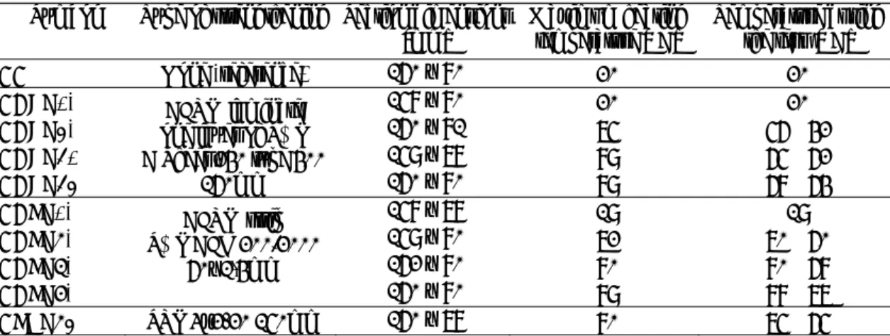
IOP Conference Series: Materials Science and Engineering
PAPER • OPEN ACCESS
FRP Strengthening of Timber Structures under the Elevated
Temperature
To cite this article: Rafal Krzywon 2019 IOP Conf. Ser.: Mater. Sci. Eng. 471 052049
View the article online for updates and enhancements.
Content from this work may be used under the terms of theCreative Commons Attribution 3.0 licence. Any further distribution of this work must maintain attribution to the author(s) and the title of the work, journal citation and DOI.
Published under licence by IOP Publishing Ltd
WMCAUS 2018
IOP Conf. Series: Materials Science and Engineering 471 (2019) 052049
IOP Publishing doi:10.1088/1757-899X/471/5/052049
1
FRP Strengthening of Timber Structures under the Elevated
Temperature
Rafal Krzywon 1
1 Silesian University of Technology, Akademicka 5, 44-100 Gliwice, Poland
Abstract. For centuries timber has been the most popular construction material. However, over the last few decades, it gave way to man-invented structural materials, it is still willingly used in civil engineering, commonly for roof constructions, ceilings but also small bridges, lookout towers. Sometimes, as a result of environmental deterioration or changes in load conditions, timber structure requires to be strengthened. Flexural or tensile performance could be simply increased by using external fiber reinforced plastic (FRP) composite sheets or strips. Such type of reinforcement almost does not change the geometry, but uncovered may be exposed to environmental influences including sunrise heating. Its temperature can exceed 70°C, while commonly as save is considered temperature below 45°C. Paper describes the bending tests of timber beams externally strengthened with three types of composites: unidirectional CFRP sheet, CFRP strip and SRP tape. Beams were heated in the various ranges of temperatures and tested in flexure. Among nine tested beams only one, heated to 95°C failed by delamination of composite overlay, the remaining beams reinforced with CFRP strips and SRP tapes could not be destroyed due to deflection outside the press cylinder range, while beams strengthened with CFRP sheets failed after rupture of carbon fibers. Experiment results show that independently of the type of reinforcement danger temperatures can be recognized over 90°C. Under that temperature behaviour of heated beams is only slightly worse than tested in room temperature and differences are visible in deflections. As a result of slippage in the adhesive layer weakened by temperature measured deformation growths. This trend applies to both CFRP strip and sheet strengthened specimens. It should be emphasized that the obtained results are much better than in the case of commonly tested reinforced concrete beams, which were subjected to delamination failure just a little above 65°C.
1. Introduction
Wood as a construction material accompanies man from the beginning of civilization development. Availability, easiness of processing has made timber the most used material for construction in the history. Even today, when we have developed a lot of artificial materials like concrete, ceramics and steel, timber remains the most willingly used housing product for roof constructions, ceilings but also small bridges, lookout towers. The use of timber in construction is continuously increasing in Europe, in UK sawn softwood use is about 0.14 m3 per capita, in Germany 0.20 m3 and in green Finland
reaches 0.80 m3 [1].
Well-preserved wood is a relatively durable material, however most of historic timber constructions is subjected in different degree to decay caused by moisture fungi and insects. A separate problem is damage caused by overloading or earthquakes or simply the need to increase bearing capacity of the structure. Most of the national heritage preservation laws limit the ability of
WMCAUS 2018
IOP Conf. Series: Materials Science and Engineering 471 (2019) 052049
IOP Publishing doi:10.1088/1757-899X/471/5/052049
2
repair to exchange of damaged wood members into the same species or to strengthen them without visible change in geometry and characteristic. These requirements can be met by fibre reinforced plastic composite materials.
The idea of strengthening of structures with externally bonded FRP composites was developed in early 1980s [2]. The first industrial applications took place in the late 1980s and concerned reinforced concrete bridges in Germany and Switzerland. Soon after, in 1991 for the first time carbon strips were used in wood construction to strengthen the historic wooden bridge in Sins, Switzerland [3], however first attempts to strengthen the timber with fibre composites were conducted in early 1960s by Wangaard [4], who tested the elastic deflection of wood-fibreglass composite beams. One of the most spectacular applications took place in Poland in the late 1990s. It was the strengthening of the wooden tower in Gliwice [5, 6], the highest timber structure in Europe (110.7 m). Both cited examples combine one feature: strengthening were bonded to external elements, directly exposed to the influence of environmental factors, including sunrays.
Nowadays the most popular strengthening systems are based on the epoxies. Epoxy resin is joining the fibers of FRP laminates, are used as primer for the substrate and finally is a base in the production of adhesives that bond laminate and structure. Epoxies belong to the group of thermosetting polymers. After curing they achieve good mechanical properties, they are strong, stiff, durable, chemically resistant, however one of the major weaknesses of epoxies is relatively low glass transition
temperature Tg, which, for commercially available epoxy resins used in structural engineering, could
appear already around 40÷50°C [7]. At that temperature epoxy polymer softens by changing its amorphous solid state into a rubbery one. That phenomenon causes the deterioration of bond between the FRP laminate and the strengthened element. For that reason, EBR FRP systems are not very resistant to elevated temperatures, they may behave poorly not only in fire but also exposed on direct solar radiation.
Glass transition is a gradual process passing in the range of 10÷20°C [8]. Mentioned above phenomenon of reduction of adhesion forces between substrate and FRP laminate is generally poorly recognized, especially there is lack of laboratory tests made on timber specimens. Currently expected behaviour of the strengthened timber structure at elevated temperature can be predicted only by analogy to concrete specimens. Actual test of flexural strengthened RC beams are showing the rapid loss of the adhesive bond strength appearing at the temperature range of 60°C and 70°C [9, 10]. Temperature over 80°C provides to total loss of capacity achieved by strengthening [11]. Weakening of adhesive makes it flexible, what provides to increase of deflection already noticeable since 45°C [12]. What important this deformation is accompanied by irreversible relaxation of stresses inside composite fibre and thus worsening of strengthening effectiveness.
Concluding, glass-liquid transition may occur at relatively low temperatures, just above 45°C. In the further part of the article, the studies of possible temperature rise caused by solar radiation will be described as well as laboratory test the behaviour of timber beams subjected to the effect of the heating corresponding to those measures.
2. Increase of temperature if the FRP system heated by the sun radiation
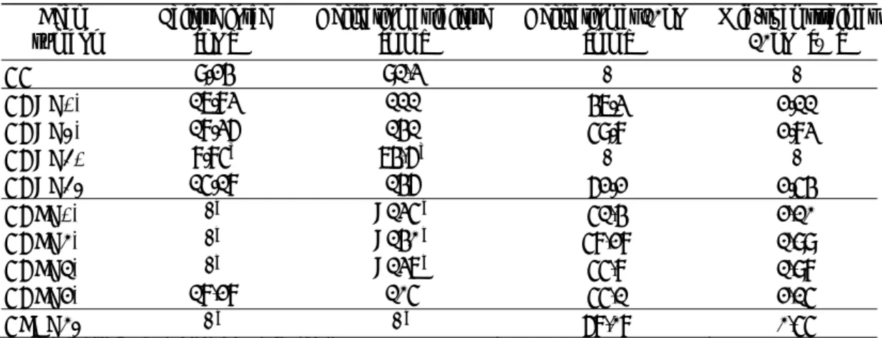
Sunrise heating causes the temperature increase in the layer of adhesive between composite overlay and concrete. Final temperature could be dependent on the time of insolation, radiation intensity and external temperature. To prove those expectation, author of this paper performed a set of tests of six types of specimens exposed to sun during the warmest days of June, July and August 2015 [13]. Among the samples there were two timber prisms, one of them with bonded CFRP strip 60x1,4mm (timber+sCFRP) and second with one layer of SRP tape 3X2-12 (timber+tSRP). Temperature changes were measured using resistant thermocouples Pt100, placed inside the 1mm thick adhesive layer. Selected results of those investigations are shown on diagrams (Fig. 1) in comparison with commonly tested concrete specimens (concrete with bonded SRP tape - concrete+tSRP and + tSRPsand, CFRP strip – sCFRP and CFRP laminated sheet – lCFRP).
WMCAUS 2018
IOP Conf. Series: Materials Science and Engineering 471 (2019) 052049
IOP Publishing doi:10.1088/1757-899X/471/5/052049
3
Figure 1. a) Maximum temperatures recorded during selected days; b) the rise of temperature [13]. During the days of sunny, unclouded weather timber specimens were able to heat up over 60°C. The highest temperature observed for the timber+sCFRP model reached 71,4°C. In most cases the temperatures achieved by wooden samples are about 10 degrees higher than concrete ones. Samples based on carbon fibers heat up a little more than SRP, what is probably associated with black colour of CFRP laminate. What is important (Fig. 1.b), timber samples need only 15 minutes to achieve glass temperature of epoxy equal to 45°C. Commonly tested concrete specimens reached this temperature about an hour later, what could be explained by good thermal resistance of timber and greater thermal inertia, what causes worse transfer of heat from the surface of the sample.
Described research proved that heated by sun, externally strengthened timber specimen is able to easy exceed the glass transition temperature and thus threaten the effectiveness and durability of strengthening system. Increase of temperature is more dependent on the intensity of sun exposure (the height of the sun above the horizon, purity of the sky) than the ambient temperature.
3. Influence of temperature on the behaviour of timber beams strengthened with CFRP
Experimental program included 10 timber beams, consisting of one unstrengthen beam, 4 beams strengthened with one layer of CFRP S&P C Sheet 240 type 400g/m2, 4 beams strengthened with
CFRP strip S&P CFK 200/2000 type 60×1,4mm and one beam strengthened with SRP tape 3x2-20. Sheets were laminated using S & P Resin 55 with declared thermal resistance up to 80 °C [14] while strips were bonded with Sikadur-30 adhesive with declared glass transition temperature 52 °C [15]. All beams were made of pine wood. Their dimensions are shown in figure 2 and table 1.
Tests were performed in four-point bending. To enlarge the effect of strengthening and avoid lateral-torsional buckling, beams were bent in the direction of lower moment of inertia. Beams were heated by three linear infra-red radiators. This method was selected as the most similar to sunrise, were heating is caused by infrared radiation rather than convection. The most efficient heating was possible after placing the heater directly under the beam. Due to the danger of damage to the radiators, this method of heating could not be continued during the test, therefore heating was provided after shifting radiators diagonally to the bottom surfaced of beam. This allowed to minimize temperature decrease during the test. Compared to the initial position of heaters, the temperature dropped by
0 10 20 30 40 50 60 70 80
June 6 June 12 July 22 August 6 August 7 August 8 timber + SRP tape timber + CFRP strip concrete+lCFRP concrete+sCFRP concrete+tSRPsand concrete+tSRP °C a) 10 20 30 40 50 60 70
10 11 12 13 14 15
m eas ured tem perature of adhes ive lay er °C 45 b) hour 45 45 45 45 45 45 45 45 45 45 45
WMCAUS 2018
IOP Conf. Series: Materials Science and Engineering 471 (2019) 052049
IOP Publishing doi:10.1088/1757-899X/471/5/052049
4
maximum 15°C. Force was applied using a hydraulic press, all beams were loaded monotonically until failure or the press cylinder range.
To determine deflections, strains, ultimate failure force beams were instrumented with linear displacement transducers in five points along the beam length (support, force application points, a middle of the span), strain gages (Fig. 1) and dynamometer under the press. Additionally, each strengthened beam was equipped with 5 Pt100 thermocouples to control the heating temperature.
Figure 2. Test lay-out.
Table 1. Characteristics of test specimens
Symbol Type of strengthening Section dimensions
[mm] Maximum heating temperature [°C] Temperature during the test [°C]
BB None (reference) 160 × 80 20 20
BCLT20 CFRP laminate
one layer of S&P C Sheet 240 type 400
160mm
158 × 80 20 20
BCLT50 160 × 81 75 56→42
BCLT62 159 × 78 89 65→62
BCLT65 160 × 80 89 68→64
BCST20 CFRP strip
S&P CFK 200/2000 60×1,4mm
158 × 78 19 19
BCST70 159 × 80 72 70→60
BCST80 162 × 80 80 80→68
BCST90 160 × 80 89 88→77
BSRT75 SRP 3x2-20 150mm 160 × 78 80 75→65
4. Test results and discussion
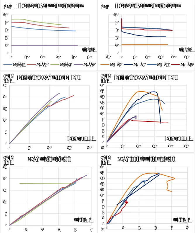
The aim of the research was to determine the effect of temperature on the effectiveness of strengthening expressed by the level of failure force and increase of deflection. Additionally, for beams reinforced with CFRP strip, slip in the adhesive layer was measured as a difference between strains of composite overlay and neighbouring timber surface.
Table 2 presents selected test results. Load-deflection curves and strains of CFRP overlay measured in mid-span zone are shown in figure 3, separately for beams strengthened with strips and laminated sheet. Diagrams are additionally complemented by a temperature variance during the test.
WMCAUS 2018
IOP Conf. Series: Materials Science and Engineering 471 (2019) 052049
IOP Publishing doi:10.1088/1757-899X/471/5/052049
5
Table 2. Selected results of laboratory research
Beam
symbol Failure force [kN] Deflection at failure [mm] Deflection at 10kN [mm] Mid-span strain at 10kN [‰]
BB 9.24 91,3 - -
BCLT20 17.83 111 47.3 2.11
BCLT50 18.36 141 59.8 2.83
BCLT62 8.85a 74,6a - -
BCLT65 15.18 146 62.2 2.54
BCST20 - b >135b 51,4 2,10
BCST70 - b >140b 58,28 1,99
BCST80 - b >137b 55,8 1,98
BCST90 18,28 105 55,1 2,15
BSRT75 - b - b 68,08 0,55
a failed due to knock at mid-span,
b achieved press cylinder range without failure, test interrupted.
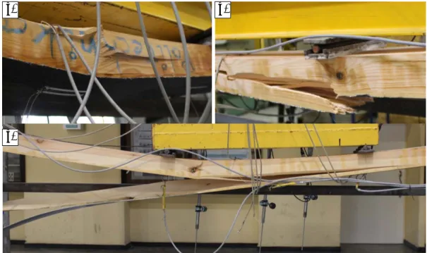
Failure force: Beams laminated with CFRP sheet failed as a result of compression in timber lamellas (BCLT20 and BCLT65, shown in Fig. 4a) or rupture of composite fibers (BCLT20 and BCLT65, shown in Fig. 4b). The lowest bearing capacity for beam BCLT62 cannot be treated as trustworthy because failure was caused by the timber defect having the form of a knot situated in the zone of maximum bending moment. That knot caused lateral deformation that cut brittle CFRP laminate. Shown in Figure 3 the loading capacity of the beam BCLT50 is closest to the beam tested at room temperature BCLT22, and the beam BCLT65 begins similar to the not strengthened beam BB.
Only one of beams strengthened with CFRP strip was successfully broken during the test. That was the beam BCST90 tested in highest temperature, around 90°C. Beam failed after delamination of composite (Fig 4c). Process of delamination appeared in the contact layer of epoxy adhesive and carbon strip. That mechanism proves the impact of elevated temperature on the mechanical properties (adhesion) of used adhesive. The remaining BCST beams and BSRT beam could not be destroyed due to limits of test device. As a result of deflection of beams the press piston reached its end position, which did not allow further application of force.
Deflection and strains: For all types of beams the increase in the intensity of thermal exposure decreases the efficiency of CFRP strengthening. This is proved both by the analysis of deflections and deformations. The effect of the epoxy glass-liquid transition process provides to the weakening of adhesive and consequently loss of strengthening effectiveness, what is noticeable as a growth of deflection. This effect can be shown by observations for the same load level (table 2). At 10 kN deflection of the BCLT50 is 26% greater than tested in room condition BCLT22, respectively for BCLT65 deflection is 31% greater. Measures obtained for BCST beams are not so visible, but still noticeable. Which is surprising, not beam BCST90 bents the most, greater deflection achieved beam BCST70, 13% higher than reference one, deflections of BCST80 and BCST90 were similar and 8% greater than BCST20.
WMCAUS 2018
IOP Conf. Series: Materials Science and Engineering 471 (2019) 052049
IOP Publishing doi:10.1088/1757-899X/471/5/052049
6
Figure 3. Measured: a) temperature drop during test duration; b) deflection; c) strain of composite overlay at mid-span.
Increasing curvature is also reflected by differences in strain of the CFRP overlay in the mid-span area of BCLT models. Other phenomena could be found for BCST beams. Except BCST90, despite the greater curvature, mid-span strains of heated beams are lower. It could be explained by the effect of slip in contact adhesive layer between timber surface and composite overlay and transfer of rising strain towards supporting zones.
0 20 40 60 80 100
0 100 200 300 400 500
adhesive temperature during the test
BCST70 BCST80 BCST90 BCST20
[°C] time [s] 0 20 40 60 80 100
-50 0 50 100 150 200 250
adhesive temperature during the test
BCLT20 BCLT50 BCLT65 BCLT62
[°C] time [s] 0 5 10 15 20 25
0 50 100 150 200
deflection of CFRP reinforced beam Force [kN] deflection [mm] -2 0 2 4 6 8 10 12 14 16 18 20
0 50 100 150 200 250
deflection of CFRP reinforced beam Force [kN] deflection [mm] 0 5 10 15 20 25
0 1 2 3 4 5
CFRP strain at midspan Force [kN] strain [‰] -2 0 2 4 6 8 10 12 14 16 18 20
0 2 4 6 8 10
CFRP lamnate strain at midspan Force
[kN]
WMCAUS 2018
IOP Conf. Series: Materials Science and Engineering 471 (2019) 052049
IOP Publishing doi:10.1088/1757-899X/471/5/052049
7
Figure 4. Observed failure modes: a) compression of timber; b) rupture of CFRP overlay; c) delamination of CFRP strip.
5. Conclusions
The scope of described investigation (a small number of tested beams), allows to treat them only as preliminary researches. Not all beams could be tested until failure, however achieved results are clearly indicating expected tendencies. Without any doubts temperature over 50°C weakens the adhesive. It is proved by growing deformability, but also noticeable under the finger touch as a softening of the laminate. These phenomena can lead to relaxation of CFRP composite and loss of strengthening effectiveness during the exploitation of structure.
Different failure models were achieved for BCLT and BCST beams. None of the beams strengthened with laminated CFRP sheet failed as a result of delamination of the composite, such a destruction model was observed only for BCST90 beam. This can be explained by different bearing capacity of one layer of carbon fiber sheet and CFK strip 60×1,4mm. Additionally strengthening based on CFRP sheets has better area of adhesion to its ultimate tensile force ratio and pure resins are more stable in elevated temperatures.
It should be stated that expected after previous tests of reinforced concrete beams, impact of temperature proved to be definitely smaller. As absolutely danger could be treated temperature above 80°C while for concrete precocious delamination failure appears little above 65°C.
Acknowledgment(s)
This paper was created as a part of the implementation of the z BK235/RB6/2017 project at the Department of Structural Engineering of Silesian University of Technology. Author wish to acknowledge for the received financing from the University.
References
[1] FAO, Food and Agriculture Organization of the United Nations. State of the World's forests, 2011.
[2] C. Czaderski, U. Meier, “EBR Strengthening Technique for Concrete, Long-Term Behaviour
and Historical Survey,” Polymers, Vol. 10, No. 77, 2018.
[3] K. Crews, A. Greenland, S. Bakkos, “Application of advanced Fibre Reinforcement Plastic
a) b)
WMCAUS 2018
IOP Conf. Series: Materials Science and Engineering 471 (2019) 052049
IOP Publishing doi:10.1088/1757-899X/471/5/052049
8
composites to structural timber,” Proceedings of 5-th World Conference on Timber
Engineering, Montreux, Switzerland, 1998.
[4] F. Wangaard, “Elastic deflection of wood–fiberglass composite beams,” Forest Production
Journal, Vol. 14, No. 6, pp. 256–260, 1964.
[5] A. Ajdukiewicz, “Rehabilitation of the Highest Wooden Tower in Poland,” Structure
Engineering International, Vol. 10, No. 3, pp. 161-163, 2000.
[6] A. Ajdukiewicz, A. Malczyk, M. Właszczuk, J. Brol, „Wooden antique radio tower in Gliwice,”
Wiadomości Konserwatorskie No 14, pp. 28-33, 2003 (in Polish).
[7] J. Michels, R. Widmann, C. Czaderski, R. Allahvirdizadeh, M. Motavalli, “Glass transition
evaluation of commercially available epoxy resins used for civil engineering applications,”
Composites Part B, Vol. 77, pp. 484-493, 2015.
[8] G. Hülder, C. Dallner, G.W. Ehrenstein, “Curing of epoxy-adhesives for the supplementary
reinforcement of buildings with bonded CFRP-straps,” Bauingenieur Vol. 81, pp. 449-454,
2006 (in German).
[9] R. Krzywoń, “Behaviour of EBR FRP strengthened beams exposed to elevated temperature,”,
Procedia Engineering, Vol. 193, pp. 297-304, 2017.
[10] J.C.P.H. Gamage, M.B. Wong, R. Al-Mahaidi, “Performance of CFRP strengthened concrete
members under elevated temperatures,” Proceedings of the International Symposium on
Bond Behaviour of FRP in Structures (BBFS 2005), pp. 113-118, 2005.
[11] J.B. Aguiar, R. Krzywon, A. Camoes, M. Górski, S. Dawczyński, “Adhesion between
high-strength concrete, epoxy and CFRP,” Proceedings: 8th International Symposium on
Utilization of High-Strength and High-Performance Concrete, pp. 239-245, 2008.
[12] T. Ulaga, U. Meier, “Long-term Behaviour of CFRP-laminate-strengthened Concrete Beams at
Elevated Temperatures,” Proceedings of the FRPRCS-5 Conference, Cambridge, July
16th-18th, pp. 147-156, 2001.
[13] R. Krzywoń, “Temperature in the adhesive layer of externally bonded composite reinforcement
heated by the sun,” ACEE Architecture Civil Engineering Environment, Vol. 9 No. 1, pp.
79-84, 2016.
[14] S&P Resin55 technical datasheet, S&P Reinforcement Poland,
http://www.sp-polska.pl/assets/files/pf3_resin_55_09.12, access 28.08.2016.
[15] Sika Sikadur-30, Thixotropic epoxy adhesive for bonding reinforcement, Sika Poland,
product data sheet,
![Figure 1. a) Maximum temperatures recorded during selected days; b) the rise of temperature [13]](https://thumb-us.123doks.com/thumbv2/123dok_us/8578627.2324471/4.892.110.782.168.555/figure-maximum-temperatures-recorded-selected-days-rise-temperature.webp)