HP StorageWorks
Enterprise Backup Solution design guide
© Copyright 2003-2005 Hewlett-Packard Development Company, L.P.
Hewlett-Packard Company makes no warranty of any kind with regard to this material, including, but not limited to, the implied warranties of merchantability and fitness for a particular purpose. Hewlett-Packard shall not be liable for errors contained herein or for incidental or consequential damages in connection with the furnishing, performance, or use of this material.
This document contains proprietary information, which is protected by copyright. No part of this document may be photocopied, reproduced, or translated into another language without the prior written consent of Hewlett-Packard. The information is provided “as is” without warranty of any kind and is subject to change without notice. The only warranties for HP products and services are set forth in the express warranty statements accompanying such products and services. Nothing herein should be construed as constituting an additional warranty. HP shall not be liable for technical or editorial errors or omissions contained herein.
Adobe® and Acrobat® are trademarks of Adobe Systems Incorporated.
Intel and Itanium are trademarks or registered trademarks of Intel Corporation or its subsidiaries in the United States and other countries. Microsoft, Windows, Windows NT, and Windows XP are U.S. registered trademarks of Microsoft Corporation.
Oracle® is a registered U.S. trademark of Oracle Corporation, Redwood City, California. UNIX® is a registered trademark of The Open Group.
About this guide. . . 7
Intended audience . . . 7
Prerequisites. . . 7
Related documentation . . . 7
Document conventions and symbols . . . 7
Rack stability . . . 8
HP technical support . . . 8
HP-authorized reseller. . . 9
Helpful web sites . . . 9
1 Overview . . . 11
Supported components . . . 11
Supported topologies . . . 11
Direct Attach SCSI . . . 11
Point-to-Point . . . 11
Switched fabric . . . 12
Platform and operating system support . . . 12
Use of native backup programs and commands . . . 12
2 Hardware Setup. . . 13
Components. . . 13
HP StorageWorks ESL E-Series tape libraries . . . 14
Ethernet connections. . . 15
SCSI connections . . . 15
Setting the bar code length . . . 17
Creating multi-unit ESL E-Series Tape Libraries using the Cross Link Kit . . . 17
HP StorageWorks EML E-series Tape Libraries . . . 18
Cabling and configuration . . . 21
Setting the bar code front panel display and host reporting configuration . . . 22
HP StorageWorks ESL9000 Series tape library . . . 23
Changing the SCSI ID settings on an ESL9000 Series tape library . . . 23
Connecting SCSI cables . . . 24
ESL9322 SCSI cable configurations . . . 24
ESL9595 SCSI cable configurations . . . 26
Default SCSI IDs . . . 28
Creating a multi unit tape library system . . . 29
HP StorageWorks MSL5000 and MSL6000 Series tape libraries . . . 30
Connecting the MSL5000/6000 tape library . . . 30
MSL5000/6000 Series library with one drive . . . 30
MSL5000/6000 Series library with two drives. . . 31
Four tape drives, dual host system. . . 32
Creating a multi-stack unit . . . 32
Setting the bar code length . . . 33
The HP StorageWorks Virtual Library System (VLS) . . . 34
Features . . . 34
VLS6105 rack order. . . 35
VLS6510 rack order. . . 35
VLS6840 rack order. . . 36
VLS6105 and VLS6510 cabling . . . 37
VLS6840 cabling. . . 38
Tape drives and performance. . . 39
Tape drives . . . 39
WORM technology . . . 39
Contents
Ultrium performance . . . 40
HP StorageWorks Interface Manager and Command View TL . . . 41
Library partitioning . . . 41
Mixed media support . . . 41
Command View TL/Secure Manager mapping algorithms . . . 41
Mapping requirements lead to rules . . . 41
Interface Manager modes: automatic and manual . . . 42
Basic vs. Advanced Secure Manager . . . 42
Interface Manager discovery. . . 43
Example . . . 43
Secure Manager mapping rules. . . 43
Single Fibre Channel Port Example . . . 47
Basic Secure Manager and manual mapping . . . 53
Interface Manager card problems . . . 54
Fibre Channel Interface Controller and Network Storage Router . . . 57
Common configuration settings . . . 57
Indexed maps . . . 58
Port 0 device maps . . . 58
Auto assigned maps. . . 59
SCC maps . . . 59
Network Storage Routers have limited initiators for single- and dual-port routers . . . 60
Fibre Channel switches . . . 60
EBS and the Multi-Protocol Router . . . 62
Fibre Channel Host Bus Adapters . . . 63
HBAs and performance . . . 63
Third-party Fibre Channel HBAs. . . 63
RAID array storage . . . 64
Raid arrays and performance . . . 64
Third-party RAID array storage . . . 64
EBS power on sequence . . . 64
3 Zoning. . . 67
Emulated Private Loop . . . 67
Increased security. . . 67
Optimized resources. . . 67
Customized environments . . . 68
Zoning components . . . 68
EBS zoning recommendations . . . 68
4 Configuration . . . 69
Basic storage domain configurations. . . 69
Nearline configuration information . . . 71
Setting up routers in the SAN environment. . . 72
About Active Fabric and SCC LUNs. . . 72
Configuring the router for systems without the Interface Manager . . . 72
HP-UX . . . 74
Initial requirement (HP-UX 11.11 on PA-RISC) . . . 74
Initial requirement (HP-UX 11.23 on IA-64 and PA-RISC) . . . 75
Configuring the SAN . . . 76
Final host configurations. . . 76
Installation checklist . . . 77
Windows NT 4.0, Windows 2000, Windows Server 2003, and Windows 2000/2003 SAK . . . 78
Configuring the SAN . . . 78
Installing HBA device drivers (Windows NT only) . . . 78
Verifying the device driver installation (Windows NT only). . . 79
Storport considerations . . . 79
Installing the HBA device driver (Windows 2000/2003). . . 79
Configuring the Emulex based FC HBA . . . 80
Windows 2000/2003 known issues . . . 81
NAS and ProLiant Storage Server devices using Microsoft Windows Storage Server 2003 . . . 83
Known issues with NAS and ProLiant Storage Servers . . . 83
Tru64 UNIX . . . 84
Backup software patch . . . 84
Configuring the SAN . . . 84
Confirming mapped components . . . 85
Installed and Configured Host Bus Adapters . . . 85
Visible target devices . . . 85
Configuring switch zoning . . . 85
Installation checklist . . . 86
Red Hat and SuSE Linux . . . 87
Install Linux . . . 87
Drivers. . . 87
Configuring the SAN . . . 87
Red Hat Enterprise Server . . . 88
SuSE Enterprise Server 8. . . 90
Additional tools . . . 91
Configuring switch zoning . . . 91
Installation checklist . . . 91
Novell NetWare. . . 93
NetWare environment considerations. . . 93
Heterogeneous Windows and NetWare environment limitations . . . 93
FCA2214 configuration settings . . . 93
Configuring switch zoning . . . 94
Installation checklist . . . 94
Sun Solaris . . . 95
Configuring the SAN . . . 95
SWSA4 adapter configuration . . . 95
FCA2257P adapter configuration . . . 96
JNI FCE6460, FCX-6562 and FCX2-6562 adapter configuration . . . 97
Recommended settings for tape . . . 98
Recommendations in a multi-switch fabric environment . . . 98
SG-XPCI1FC-QF2 (X6767A), SG-XPCI2FC-QF2 (X6768A), SG-XPCI1FC-JF2, or SG-XPCI2FC-JF2 adapter configuration . . . 99
Troubleshooting with the cfgadm Utility for the Sun StorEdge SG-XPCI1FC-QF2, SG-XPCI2FC-QF2, SG-XPCI1FC-JF2 and SG-XPCI2FC-JF2 HBAs . . . 100
Emulex LP9002L / LP10000 / LP10000DC adapter configuration . . . 100
Configuring Sun Servers for tape devices on SAN . . . 102
Configuring switch zoning . . . 103
Installation checklist . . . 103
Troubleshooting for Sun StoreEdge FC host bus adapters . . . 104
IBM AIX. . . 105
Configuring the SAN . . . 105
Cambex PC1000/2000F HBA. . . 105
Confirming mapped components and configuring devices with the Cambex HBA . . . 106
IBM 6228, 6239, or 5716 HBA configuration . . . 106
Configuring switch zoning . . . 108
Installation checklist . . . 108
5 Management Tools . . . 109
HP OpenView Storage Area Manager . . . 109
Library and Tape Tools . . . 109
HP Systems Insight Manager (HP SIM). . . 109
Features: . . . 109
Key benefits: . . . 110
Management agents . . . 110
Known issues . . . 110
Recommendations . . . 110
6 High Availability . . . 113
Multi-path failover software for disk arrays (MPIO). . . 116
EBS-specific requirements . . . 116
HP StorageWorks Secure Path . . . 117
Secure Path software . . . 117
EBS-specific requirements . . . 117
HP StorageWorks AutoPath XP. . . 117
Features . . . 117
EBS-specific requirements . . . 117
AutoPath VA . . . 117
Features . . . 118
Clustering . . . 118
Highlights . . . 118
Benefits . . . 118
EBS Support of failover versus non-failover applications . . . 120
EBS clustering with failover . . . 120
EBS clustering with no failover support . . . 121
HP-UX MC/ServiceGuard . . . 121
7 Extended Copy . . . 123
HP support of XCopy . . . 123
Standard extended copy topology . . . 123
Planning an XCopy solution . . . 124
XCopy best practices . . . 124
Known Issues . . . 125
About this guide
This design guide provides information to help you design an HP StorageWorks Enterprise Backup Solution.
Intended audience
This guide is intended for use by system administrators implementing an EBS, who are experienced with the following:
• Tape backup technologies, tape libraries, and backup software
• SAN environments
• Fibre Channel
Prerequisites
Before you install your EBS hardware, make sure you consider the items below:
• Review of the EBS compatibility matrix to be sure that the components you have selected are listed
• Knowledge of the operating system(s)
• Knowledge of EBS hardware components listed in Chapter 1
• Knowledge of switch zoning and selective storage presentation
Related documentation
• In addition to this guide, HP provides corresponding information:
• EBS Compatibility Matrix
• Implementation Guides for supported backup applications
• Installation Guides for EBS hardware components
Document conventions and symbols
Table 1 Document conventions
Convention Element
Medium blue text: Figure 1 Cross-reference links and e-mail addresses
Medium blue, underlined text
(http://www.hp.com) Web site addresses
Bold font • Key names
• Text typed into a GUI element, such as into a box
• GUI elements that are clicked or selected, such as menu and list items, buttons, and check boxes
Italics font Text emphasis
Monospace font • File and directory names • System output
• Code
• Text typed at the command-line
Monospace, italic font • Code variables
• Command-line variables
Monospace, bold font Emphasis of file and directory names, system output, code, and text
WARNING! Indicates that failure to follow directions could result in bodily harm or death.
CAUTION: Indicates that failure to follow directions could result in damage to equipment or data.
IMPORTANT: Provides clarifying information or specific instructions.
NOTE: Provides additional information.
TIP: Provides helpful hints and shortcuts.
Rack stability
WARNING! To reduce the risk of personal injury or damage to equipment:
• Extend leveling jacks to the floor.
• Ensure that the full weight of the rack rests on the leveling jacks.
• Install stabilizing feet on the rack.
• In multiple-rack installations, secure racks together.
• Extend only one rack component at a time. Racks may become unstable if more than one component is extended.
HP technical support
Telephone numbers for worldwide technical support are listed on the HP support web site:
http://www.hp.com/support/.
Collect the following information before calling:
• Technical support registration number (if applicable)
• Product serial numbers
• Product model names and numbers
• Applicable error messages
• Operating system type and revision level
• Detailed, specific questions
For continuous quality improvement, calls may be recorded or monitored.
HP strongly recommends that customers sign up online using the Subscriber's choice web site:
http://www.hp.com/go/e-updates.
• Subscribing to this service provides you with e-mail updates on the latest product enhancements, newest versions of drivers, and firmware documentation updates as well as instant access to numerous other product resources.
• After signing up, you can quickly locate your products by selecting Business support and then Storage under Product Category.
HP-authorized reseller
For the name of your nearest HP-authorized reseller:
• In the United States, call 1-800-345-1518.
• Elsewhere, visit the HP web site: http://www.hp.com. Then click Contact HP to find locations and telephone numbers.
Helpful web sites
For third-party product information, see the following HP web sites:
• http://www.hp.com
• http://www.hp.com/go/storage
• http://www.hp.com/support/
1
Overview
The HP StorageWorks Enterprise Backup Solution (EBS) is an integration of data protection software and industry-standard hardware, providing a complete enterprise class solution. HP has joined with leading software companies to provide software solutions that support the backup and restore processes of homogeneous and heterogeneous operating systems in a shared storage environment.
EBS software partner’s data protection solutions incorporate database protection, storage management agents, and options for highly specialized networking environments.
Data protection software focuses on data backup and restore using an automated LTO Ultrium, SuperDLT, or DLT tape library and Fibre Channel technology. The EBS combines the functionality and management of Fibre Channel Storage Area Network (SAN), data protection software, and scaling tools to integrate tape and disk storage subsystems in the same SAN environment.
Enterprise data backup and restore can be accomplished with different tape devices in various configurations, using a variety of transport methods such as the corporate communication network, a server SCSI bus, or a Fibre Channel infrastructure. EBS uses a storage area network (SAN) that provides dedicated bandwidth independent of the local area network (LAN). This independence allows single or multiple backup or restore jobs to run without the network traffic caused by data protection environments. Depending on the backup software used, submitted jobs are run locally on the backup server to which the job was submitted. Data, however, is sent over the SAN to the tape library rather than over the LAN. This achieves greater speed and reduces network traffic. Jobs and devices can be managed and viewed from either the primary or any server or client connected within the EBS which has the supported data protection software solution installed. All servers within the EBS server group can display the same devices.
The first step in implementing an EBS solution is to consult the EBS Compatibility Matrix available at: http://www.hp.com/go/ebs
This EBS design guide is the second step in implementing your Enterprise Backup Solution. This guide describes the EBS hardware configurations currently supported and how to efficiently and effectively provide shared tape library backup in a heterogeneous SAN environment.
The third step in implementing your Enterprise Backup Solution is installing and configuring your backup application or backup software. Rules and recommendations for individual backup applications and software may be found in separate implementation guides.
For more information about EBS, go to http://www.hp.com/go/ebs.
Supported components
For complete EBS configuration support information, refer to the EBS Compatibility Matrix located at: http://www.hp.com/go/ebs
Supported topologies
A Fibre Channel SAN supports several network topologies, including point-to-point and switched fabric. These configurations are constructed using switches and routers.
Direct Attach SCSI
Direct Attach SCSI (DAS) is the most common form of attachment to both disk and tape drives. DAS allows a single server to communicate directly to the given target device over a SCSI cable. DAS configurations do not allow for multihosting a single target device as the target device is dedicated to the server. DAS configurations are not covered in this document.
Point-to-Point
Point-to-Point, or Direct Attach Fibre (DAF), connections are direct Fibre Channel connections made between two nodes, such as a server and an attached tape library. This configuration requires no switch to implement. It is very similar to a SCSI bus model, in that the storage devices are dedicated to a server.
Switched fabric
A switched-fabric topology allows nodes to talk directly to each other through temporarily established direct connections. This provides simultaneous dedicated bandwidth for each communication between nodes.
Because of this, switched fabric topologies provide significantly more performance and scalability than arbitrated loop topologies.
Also, switched fabric topologies do not suffer from susceptibility to I/O interruptions due to errors, resets, or power failures from third party nodes. Because communications are established directly between nodes, interruption events are isolated by the fabric environment.
Finally, because many nodes never need to communicate with each other, such as between two hosts, interoperability issues are significantly reduced in a fabric topology as compared to loops. Nodes need only interoperate with the switch and the target node instead of every node on the loop or fabric.
Switched fabric configurations are implemented with Fibre Channel switches. Switches may be cascaded or meshed together to form larger fabrics.
NOTE: See Figure 14, Figure 15, and Figure 27 for an example of basic switched fabric, point-to-point, and direct attached SCSI configurations.
Platform and operating system support
Library sharing in a heterogeneous environment is supported. All platforms may be connected through one or more switches to a tape library. The switches do not need to be separated by operating system type, nor do they have to be configured with separate zones for each operating system.
The host server needs to detect all of the tape and robotic devices intended to be used; shared access to tape drives is handled by the backup application software running on each host.
While some operating systems found in enterprise data centers may not be supported on the storage network by EBS, it is still possible to back up these servers as clients over the LAN and still be supported. See Figure 14 for a diagram that includes LAN client connections. Refer to your ISV compatibility matrix for more information.
Use of native backup programs and commands
A limited number of backup programs and commands that are native to a particular operating system (such as tar, cpio, dd, fbackup, NTBackup, and so on) are verified for basic functionality with SCSI
direct-attached autoloaders only. Tape libraries and virtual library systems are not tested. These programs and commands are limited in their ability to handle complicated backups and restores in multi-host, storage area networks (SANs). They are not guaranteed to provide robust error handling or performance throughput. Use of these programs and/or commands in a user developed script is not recommended for use with tape libraries in an Enterprise Backup Solution shared storage environment. Refer to the EBS compatibility matrix at http://www.hp.com/go/ebs for a list of tested and supported applications that are specifically designed for backup and restore operations.
2.
Hardware Setup
Components
Table 2 provides a description of the key components comprising a SAN backup solution.
NOTE: For a complete listing of supported servers and hardware, refer to the HP Enterprise Backup Solutions compatibility matrix at http://www.hp.com/go/ebs.
For more information on HP StorageWorks libraries, see http://www.hp.com/go/tape.
Table 2 SAN backup components
Component Description
Host Bus Adapter Host bus adapters (HBAs) are used to connect servers to Fibre Channel topologies. They provide a similar function to SCSI host bus adapters or network interface cards (NIC). The device driver for an HBA is typically responsible for providing support for any of the Fibre Channel topologies – point-to-point, loop, or fabric. In most cases, the device driver also provides a translation function of presenting Fibre Channel targets as SCSI devices to the operating system. This provides compatibility with existing storage applications and file systems that were developed for SCSI devices.
Switch Switches are the Fibre Channel infrastructure component used to construct fabrics. Switches may be cascaded together to configure larger fabrics.
Switches typically have an Ethernet port for managing them over the network. This port provides status and configuration for the switch and individual ports.
Tape Library The tape library and tape drives it contains provide the nearline storage for backup on the SAN. The tape library provides automated tape handling which becomes a key requirement when consolidating backup across multiple servers.
Fibre Channel
Interface Controller The controller (also referred to as a bridge or router) device provides connection between Fibre Channel networks and SCSI tape and robotic devices. This device is similar to a Fibre Channel disk controller for RAID subsystems. The controller acts as an interface to the SCSI device, and can send or receive SCSI commands through encapsulated Fibre Channel frames.
Fibre Channel
Interface Manager The Interface Manager card, in conjunction with HP StorageWorks Command View TL software, provides remote management of the library via a serial, telnet, or web-based GUI interface.
Cables and SFPs Three types of cables exist to connect Fibre Channel devices together – copper cables, short-wave or multi-mode optical cables, and long-wave or single-mode optical cables. Each type of cable provides different maximum lengths, as well as cost.
Fibre Channel devices have ports which either require a specific type of cable, or require a separate module referred to as an SFP (Small Form-factor Pluggable). An SFP-based port allows the customer to use any type of cable by utilizing the appropriate type of SFP with it. For example, Fibre Channel ports use fibre-optic SFP modules with LC connectors.
Data Protection
Software Data protection software is deployed on each of the hosts on a SAN that will perform backup. This typically requires installing server-type licenses and software on each of these hosts. Many of these backup applications also provide a separate module or option, which enables software to manage shared access to the tape drives on a SAN. This may need to be purchased in addition to the typical software licenses.
SAN Management
Software SAN Management software is used to manage resources, security, and functionality on a SAN. This can be integrated with host-based device management utilities or embedded management functionality such as switch Ethernet ports.
HP StorageWorks ESL E-Series tape libraries
The HP StorageWorks ESL E-Series enterprise tape library scales up to 712 LTO or 630 SDLT cartridge slots in a single library frame, 1410 LTO slots or 1248 SDLT slots in a dual frame. Offered with Ultrium 460, Ultrium 960, SDLT 320, and SDLT 600 tape technologies, the ESL E-Series offers storage density of up to 28.4 terabytes per square foot of floor space.
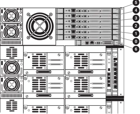
Each single library frame may contain up to 24 tape drives (four drives per drive cluster) as shown in
Figure 1. Each library frame must contain at least one drive cluster. In a dual frame library, where two frames are joined into a single library using the Cross-Link Mechanism, the first frame may contain up to 20 drives and the second frame may contain up to 24 drives.
Figure 1 Drive cluster numbering
ACT/LNK ACT/LNK PORT 1 PORT 0 ETHERNET SERIAL PWR FIBRECHANNEL FIBRECHANNEL
ACT/LNK ACT/LNK PORT 1 PORT 0 ETHERNET SERIAL PWR FIBRECHANNEL FIBRECHANNEL
ACT/LNK ACT/LNK PORT 1 PORT 0 ETHERNET SERIAL PWR FIBRECHANNEL FIBRECHANNEL ACT/LNK ACT/LNK PORT 1 PORT 0 ETHERNET SERIAL PWR FIBRECHANNEL FIBRECHANNEL
ACT/LNK ACT/LNK PORT 1 PORT 0 ETHERNET SERIAL PWR FIBRECHANNEL FIBRECHANNEL
ACT/LNK ACT/LNK PORT 1 PORT 0 ETHERNET SERIAL PWR FIBRECHANNEL FIBRECHANNEL Cluster 5 Cluster 4 Cluster 3 Cluster 2 Cluster 1
Cluster 0 with Interface Manager
Cluster 0 with 4Gb Interface Controller Interface Controller
Interface Manager (Depending on configuration)
15321
Interface Manager
(depending on configuration)
Interface Controller
-Or-A drawing showing the cluster numbering and drive positioning is located inside the rear door. See
Figure 2. Drive clusters are numbered starting at the top of the cabinet beginning with 0.
Figure 2 Cluster and drive numbering
Ethernet connections
Table 3 identifies the cluster controller Ethernet ports and shows the connection locations for the Ethernet cable in a multiple drive cluster configuration.
SCSI connections
Connect the SCSI cables from the drives in drive cluster 0 (see Figure 1) to the e2400-160 interface controller in slot 0 (see Figure 4) of the card cage.
Drive SCSI cables are labeled A, B, C, and D on the drive end to indicate the drive location. See Figure 3. Drive SCSI cables are labeled 0, 1, 2, and 3 on the Fibre Channel interface controller end to indicate the SCSI port location. The most efficient order for making these connections is as follows:
A B C D A B C D A B C D A B C D A B C D A B C D 1 2 3 4 5 6 7 8 9 10 11 12 13 14 15 16 17 18 19 20 21 22 23 24
Table 3 Multiple drive clusters Drive cluster Cluster controller
Ethernet port Ethernet cable
0 E1 Cabinet controller
E2 Interface Manager card E3 Interface Controller
E4 Daisy-chain to lower cluster controller 1 E1 Daisy-chain to upper cluster controller
E2 e1200-160 robotics controller (if present) E3 Interface Controller
E4 Daisy-chain to lower cluster controller 2-5 E1 Daisy-chain to upper cluster controller
E2 Not used
E3 Interface Controller
E4 Daisy-chain to lower controller (not used for cluster 5)
2. Connect a SCSI cable from drive B to port 1 on the interface controller.
3. Connect a SCSI cable from drive C to port 2 on the interface controller.
4. Connect a SCSI cable from drive A to port 0 on the interface controller.
Figure 3 SCSI connections
Figure 4 Identifying e2400-160/e2400-FC 2G Interface Controller slots
One Interface Controller, supporting up to four tape drives, is required per drive cluster. Each tape drive should be connected to its own port on the Interface Controller.
Use the top six slots, referenced in Figure 4 as 0 through 5, to match the numbering of the corresponding drive clusters. For example, drive cluster 0 should correspond to controller 0. Consequently, the 2Gb Interface Controllers (e2400-160 FC and e2400-FC 2G) should be installed beginning with the lowest available slot in the card cage. The 4Gb Interface Controller (e2400-FC 4G) should be installed in the rightmost two card slots of the drive cluster with which it is associated. Slot 6 contains either the e1200-160 robotics controller or the Interface Manager, depending upon the library configuration.
5 4 3 2 1 0 6
Setting the bar code length
To change the bar code length:
1. Access the front panel display and select Menu.
2. Select Setup.
3. Enter the password.
4. Scroll down to bar code length and enter the desired length. The default length is 6.
Creating multi-unit ESL E-Series Tape Libraries using the Cross Link Kit
HP StorageWorks ESL Cross Link Kit connects two 712e or 630e tape libraries together as a single tape library to scale up to 1410 LTO slots (564 TB) or 1248 SDLT slots (374 TB) and up to 44 tape drives. The ESL E-Series Cross Link Kit requires specific software and firmware supplied on CD with the Cross Link Kit. Software licenses are required only on the first or primary library frame.
Small count tape libraries (322e, 286e) are only supported if upgraded to a fully populated tape library, and only if they are the first or primary tape library.
NOTE: The Cross Link Kit requires removal of one cluster of either tape drives or slots along the back wall of the first ESL cabinet. In an LTO library, the back wall clusters hold 14 slots. In an SDLT library, the back wall clusters hold 12 slots.
HP StorageWorks EML E-series Tape Libraries
The HP StorageWorks EML E-series library is available in two models-the 103e, which is a 12U
rack-mounted design containing up to four tape drives and 103 LTO tape slots, and the 245e, which is a 24U rack-mounted design holding up to eight drives and 245 LTO slots. Upgrade kits are available to fill out a 42U rack with a configuration that can contain up to 442 LTO slots and 16 tape drives.
The Fibre-Channel LTO drives are connected to a SAN fabric via e2400-FC 2G/4G interface controllers, which are in turn managed by the HP StorageWorks Interface Manager card. HP StorageWorks
Command View TL is used to communicate with the interface manager via web browser for configuration.
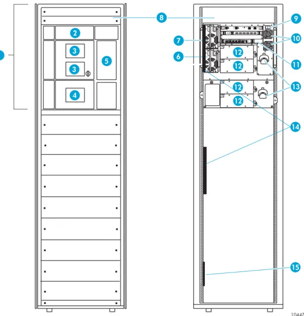
Figure 6 Enterprise Modular Library, model 103e
1 Base module 2 Robotics unit (parked) 3 Viewing window 4 Operator control panel
5 Load port (S-cartridge capacity) 6 Redundant module power supply (optional)
7 Module primary power supply 8 Customer reserved space (2U) 9 Library main power switch 10 Library fans
11 Base module card cage 12 Tape drives
13 Cable management features 14 Extension bars (power strips) 15 Power distribution units
10447
1 3
2
3
4
5
12 12 12 12 6
7
8 9
10
11 13
14
15 6
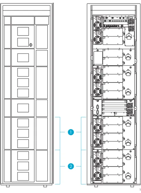
Figure 7 Enterprise Modular Library, model 245e
1 See model 103e (Figure 6) 2 Tape drive expansion module 3 Card cage expansion module 4 Viewing window
5 Load port (10-cartridge capacity) 6 Module primary power supply 7 Redundant module power supply
(optional) 8 Tape drives
9 Cable management features 10 Card cage module fans 11 Redundant card cage power
supplies
10448
3 1
2
3
4 4 4
5
8 8 8 8
9
10
11 6
7
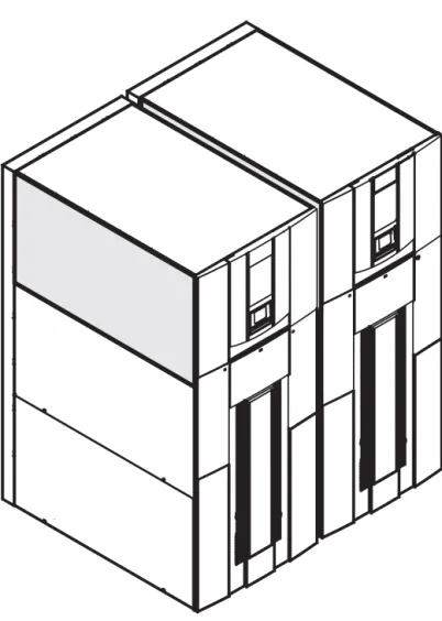
Figure 8 Example of a fully expanded Enterprise Modular Library
1 Tape drive expansion module 2 Capacity expansion module 1 3
2 1
Cabling and configuration
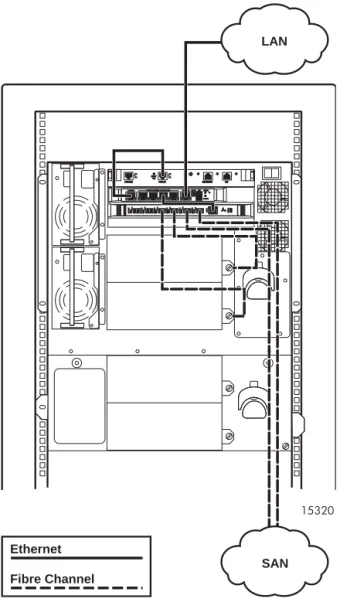
Figure 9 EML cabling
Figure 9 shows the back of an EML 103e library with the robotic controller card at the top, the Interface Manager (IM) card just below, the Interface Controller (IC) card, and the tape drive enclosures at the bottom. The tape drives are connected to the Interface Controller via fiber cable. The top-most drive (drive 0) should be connected to the tape drive 0 (TD 0) port on the IC, with the rest following in sequence. The Ethernet port on the IC is connected to the FC controller ports on the IM card. For better organization, connect each IC to the IM Ethernet ports in sequential order, although this is not required.
The IM is connected to the robotic controller via Ethernet from the IM Cascade port to the Public port on the robotic controller card.
After cabling the library as described above, the library can be powered on. When the initialization process is complete, do the following:
1. Access the library via the front touch panel to configure the network settings.
2. Select the Configuration tab.
3. Select Library Configuration and then Change Network Settings.
4. Enter the library administration password.
5. Choose either DHCP or Manual in the Address Config field. If Manual was selected, touch the IP address and change the address to the desired setting. Repeat this for the subnet mask, gateway, and DNS server, if applicable.
6. When complete, press Save. The EML is now accessible via the Command View TL browser interface
15320
LAN
SAN Ethernet
Setting the bar code front panel display and host reporting configuration
HP StorageWorks EML E-Series Tape Libraries bar code reporting can be configured as six to eight characters and left or right aligned. If six characters with left alignment is chosen, any characters after the sixth are truncated. With six characters and right alignment, only the last six characters are shown with the beginning characters truncated.
The LTO labels have L1, L2, and L3 as the media identifiers for the respective LTO1, LTO2, and LTO3 cartridges. All cleaning cartridges should use the format CLNxxxL1 type of label, where xxx is a number between 000 and 999 for all types of LTO drives. WORM tape cartridges for LTO3 have media identifiers of LT. The length and justification of the bar code reporting format, as sent to the host and as viewed on the front panel, can be configured through the front panel configuration section.
To set the bar code front panel display and host reporting configuration on the EML library:
1. Access the EML front panel top display and select the Configuration tab.
2. Select the Library Configuration tab and enter the password (the default password for EML is 112233).
3. Select the Configure barcode reporting format tab.
4. Select Format for Front Panel and configure according to the requirements listed above.
HP StorageWorks ESL9000 Series tape library
The HP StorageWorks ESL9000 Series tape library is an automated storage and retrieval library. It contains up to 8 drives and 322 cartridges for the ESL9322 Series, and up to 16 tape drives and 595 cartridges for the ESL9595 Series.
The ESL9000 Series tape library models support a wide range of storage and performance requirements.
Changing the SCSI ID settings on an ESL9000 Series tape library
The first step in installing the ESL9000 Series Tape library is changing the SCSI ID settings. SCSI settings should be unique for each SCSI bus. HP recommends that the SCSI IDs be sequential starting with 0.
NOTE: The following steps may not be necessary with newer libraries.
Use the control panel located on the tape library to change the SCSI ID settings.
1. Select Standby to take the library off-line.
2. Select Operator to enter the operator screen. The Operator screen is restricted for use by individuals with operator or service access privileges.
3. Type the password numbers on the keypad and press Enter when prompted for a password.
NOTE: The default password is 1234.
4. SelectConfigure Library.
5. The Configure Library Menu displays a list of devices and current settings. To change the settings, select
Configure.
6. The Configure Library Settings screen is displayed. Press Select until Device is highlighted.
7. Press the Left Arrow and Right Arrow buttons to select the device to be changed.
NOTE: As the operator scrolls through the list of devices, the SCSI ID field simultaneously displays the SCSI ID settings of the currently selected device.
8. When the device has been highlighted, press Select one time to highlight the SCSI ID field.
9. Press theLeft Arrow and Right Arrow buttons to scroll through the list of SCSI IDs.
10.When the desired setting is displayed, press Change to save the settings as part of the library configuration.
11.Repeat steps 7 through 10 to configure additional devices.
NOTE: The library must be power-cycled before new SCSI ID settings are effective.
NOTE: The default drive cable/library configuration should be used for the robot and drives, with the exception of the SCSI ID assignments.
Connecting SCSI cables
This section describes the supported SCSI cable configurations for the ESL9000 series tape libraries.
ESL9322 SCSI cable configurations
Figure 10 shows the SCSI ports as viewed from the rear of the ESL9322 tape library.
Figure 10 SCSI ports (ESL9322)
Looking from the back of the ESL9322 tape library, connect the SCSI cables and terminators as shown in
Figure 11.
NOTE: ESL9322 series libraries are equipped with internal SCSI cables and terminators in place for a one drive per SCSI bus configuration. This is the recommended configuration (and the required
configuration for Ultrium 460, Ultrium 960, and SDLT 600 drives) and ensures optimal performance.
Figure 11 shows the internal SCSI cabling. The connectors are on the SCSI ports that are shown in
Figure 10.
NOTE: Drive numbering begins with 0. Consequently, the first drive is drive 0, the second drive is drive 1, and so on.
DIAG.
D E F G
DRIVE POSITION
H
I J B C
CONT. K
L PTM
A
1 2 3 4 5 6 7
9 0
8
EXPANSION DRIVES
Figure 11 internal SCSI cabling configuration (ESL9322)
1 Terminators (8) 2 SCSI cables (8) 3 Drive column 1 4 Robotic controller 5 Host SCSI cable
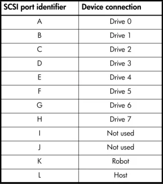
Table 4 SCSI ports and device connections (ESL9322) SCSI port identifier Device connection
A Drive 0
B Drive 1
C Drive 2
D Drive 3
E Drive 4
F Drive 5
G Drive 6
H Drive 7
I Not used
J Not used
K Robot L Host E SCSI A SCSI SCSI I L J K SCSI SCSI SCSI C SCSI B SCSI D SCSI G SCSI F SCSI H SCSI Drive # 0
SCSI ID 1 Drive # 1 SCSI ID 2 Drive # 2 SCSI ID 3 Drive # 3 SCSI ID 4 Drive # 4 SCSI ID 1 Drive # 5 SCSI ID 2 Drive # 6 SCSI ID 3 Drive # 7 SCSI ID 4
1 4 3 1 1 1 2 2 2 2 2 2 2 2 1 1 1 1 5
ESL9595 SCSI cable configurations
Figure 12 shows the SCSI ports as viewed from the rear of the ESL9595 tape library.
Figure 12 SCSI ports (ESL9595)
Looking from the rear of the library, connect the SCSI cables and terminators as shown in Figure 13.
NOTE: ESL9595 series libraries are equipped with internal SCSI cables and terminators in place for a one drive per SCSI bus configuration. This is the recommended configuration (and the required
configuration for Ultrium 460, Ultrium 960, and SDLT 600 drives) and ensures optimal performance.
Figure 13 shows the internal SCSI cabling. The connectors are on the SCSI ports that are shown in
Figure 12.
NOTE: Drive numbering begins with 0. Consequently, the first drive is drive 0, the second drive is drive 1, and so on.
DIAG.
CONT. R
Q PTM
D E F G H
B C A
DRIVE POSITION
3 4 5 6 7
1 2 0
I J
O N M L K
P
8 9 14 13 12 11 10 15
Figure 13 Internal SCSI cabling configuration (ESL9595) 1 SCSI cables (16) 2 Terminators (16) 3 Robotic controller 4 Drive column 1 5 Drive column 0 6 Host SCSI cable
Table 5 SCSI ports and device connections (ESL9595) SCSI port identifier Device connection
A Drive 0
B Drive 1
C Drive 2
D Drive 3
E Drive 4
F Drive 5
G Drive 6
H Drive 7
I Drive 8
J Drive 9
K Drive 10
L Drive 11
M Drive 12
N Drive 13
O Drive 14
P Drive 15
Q Host
R Robot
Drive # 8 Drive # 9 Drive # 10 Drive # 11 Drive # 12 Drive # 13 Drive # 14 Drive # 15
Drive # 0 Drive # 1 Drive # 2 Drive# 3 Drive # 4 Drive # 5 Drive # 6 Drive # 7
A B C D E F G H P
Q
O N M L K J I 4 3 5 1 2 1 2 1 2 2 1 2 1 2 1 2 1 2 1 R 1 2 1 2 1 2 2 1 2 1 2 1 2 1 2 1 6 1
Default SCSI IDs
Table 6 lists the default SCSI IDs for the ESL9000 Series tape library.
NOTE: The ESL9322 holds a maximum of 8 tape drives, with tape drive 7 being the highest-numbered tape drive. The ESL9595 holds a maximum of 16 tape drives, with tape drive 15 being the
highest-numbered tape drive.
Table 6 Default SCSI IDs
Drive number Default SCSI ID
Tape library 0
Drive 0 1
Drive 1 2
Drive 2 3
Drive 3 4
Drive 4 1
Drive 5 2
Drive 6 3
Drive 7 4
Drive 8 1
Drive 9 2
Drive 10 3
Drive 11 4
Drive 12 1
Drive 13 2
Drive 14 3
Creating a multi unit tape library system
The HP StorageWorks ESL9000 Series pass-through mechanism (PTM) enables the transfer of a single tape cartridge between two HP StorageWorks ESL9000 Series Tape Libraries. The PTM can be used to connect up to five ESL9322/9326/9198 libraries or up to four ESL9595 libraries (one PTM for every two libraries) creating a multi unit tape library system.
HP StorageWorks MSL5000 and MSL6000 Series tape libraries
Each of the tape drives and the library controller constitute an independent SCSI target. When any two or more devices are connected to the same SCSI bus, each separate SCSI device must be assigned a unique SCSI ID.
Connecting the MSL5000/6000 tape library
WARNING! Make sure the power to each component is off and the power cords are unplugged before making any connections.
NOTE: Read the documentation included with each component for additional operating instructions before installing.
Connect theLibrary to the router using a SCSI interface cable (refer to the HP StorageWorks MSL5000 and 6000 Series Tape Library User Guide for interface cable specifications). One router SCSI port supports up to two drives and one robotic device. Only one SCSI cable is needed for a single tapelibrary module.
MSL5000/6000 Series library with one drive
When connecting one drive, use a LVD SCSI terminator to terminate the remaining SCSI port for drive 1.
Figure 15 Cabling an MSL5026/6030 with a single-drive configuration 1 SCSI cable 2 SCSI jumper cable 3 Terminator
1
2 3
MSL5000/6000 Series library with two drives
When connecting two drives, use a SCSI jumper cable to connect drive 1 to drive 2. With a LVD SCSI terminator, terminate the remaining SCSI port for drive 2.
Figure 16 Cabling an MSL5026/6030 with a two-drive configuration 1 SCSI jumper cable 2 SCSI cable
3 SCSI jumper cable 4 Terminator
1 2
3 4
Four tape drives, dual host system
Figure 17 shows a typical SCSI cable configuration for a library with four tape drives installed using a dual host system.
Figure 17 SCSI cable configuration (four tape drives, dual host system)
NOTE: Daisy-chaining Ultrium 460, Ultrium 960, and SDLT 600 drives is not recommended due to degraded performance.
Creating a multi-stack unit
The MSL5000 and MSL6000 series libraries can be stacked in a scalable combination with additional MSL5000 or MSL6000 series libraries to form a multi-unit, rack-mounted configuration. Through use of a pass-thru mechanism (PTM), all multi-unit libraries in the stack can operate together as a single virtual library system. Stacked units are interconnected through their rear panel Ethernet connections and an external Ethernet hub mounted to the rack rails.
The external Ethernet hub also provides an additional connector when libraries are combined in their maximum stacked height.
• A maximum of eight libraries can be connected in this manner.
• Any combination of libraries, not exceeding 40U in total stacked height, can also be used.
• A multi-unit library system appears to the host computer system and library control software as a single library.
• For multi-unit applications, the top library becomes the primary master unit and all other lower libraries are slave units.
1 SCSI Terminator 2 0.5 m jumper cables
3 RS-232 diagnostic cable (for service only) 4 To Host System 5 0.25 m or 0.5 m jumper cable
1
2
5
5
4
3
NOTE: The PTM continues to function each time a slave library is physically removed from the rack configuration during normal library operation.
The library robotics can pick and place tape cartridges into a movable elevator that encompasses the full length of the PTM. In this manner, individual tapes can be passed up or down between the libraries contained in the stack. Robotic access to the PTM is located at the rear of the unit, between the tape drives and the power supply. The library also supports fail-over protection for multi-unit, rack-mounted
applications. For example, if the primary master library fails, you can invoke the library system fail-over mode. In this mode, one of the connected slave units serves as the secondary master library that now communicates with the host system through the SCSI interface. The PTM drive motor source power is relay-switched from the original primary master library to the newly assigned secondary master library.
Figure 18 MSL5026/6030 stack configuration
Setting the bar code length
1. Access the front panel and select Menu.
2. Select Edit Options.
3. Select Library.
4. Enter password.
5. Scroll down to bar code options and enter the desired values. The default values are as follows: • Barcode label size = 8
• Barcode alignment = Left Align • Barcode label check digit = Disabled • Barcode reader = Retries enabled
The HP StorageWorks Virtual Library System (VLS)
Integrating seamlessly into existing backup applications and processes, the HP StorageWorks 6000 Virtual Library System (VLS 6000) accelerates backup performance in complex SAN environments while
improving overall reliability. Emulating popular tape libraries and tape drives, the VLS 6000 matches the existing data protection environment, removing the need to change backup software or monitoring policies. By emulating multiple tape drives simultaneously, more backup jobs can be done in parallel resulting in reduced backup times. Additionally, because the data resides on disk, single file restores are exceptionally fast.
The HP StorageWorks 6000 Virtual Library System (VLS) is a RAID 5, Serial ATA disk-based SAN backup device that emulates HP's physical tape libraries. This configuration allows disk-to-virtual tape (disk-to-disk) backups to be performed using existing backup application(s).
Features
• Emulates popular tape drives and libraries
• Up to 16 libraries and 64 drives emulated simultaneously within a single virtual library system
• Certified with popular backup software packages through HP StorageWorks Enterprise Backup Solution
• Over 575 MB/s throughput
• Scales capacity and performance
• Data compression
• Hot Swap array drives
• Redundant array power supplies and cooling
• RAID 5
• Mounts in a standard 19-inch rack
NOTE: With the HP VLS6000-series virtual library, bar code templates are created for use with the virtual cartridges on which data is stored. These bar codes can have as few as two characters or as many as 99, and they are completely configurable by the administrator.
When configuring the bar code templates, care should be taken to follow the requirements (if any) for bar code prefixes and length per the backup application. In addition, it is a good idea to use a bar code prefix that differs from any physical cartridge bar codes in a tape library to which data may be migrated behind the VLS. That way, physical and virtual cartridges can be easily recognized from within the backup application.
VLS6105 rack order
Figure 19 VLS6105 rack order
VLS6510 rack order
Figure 20 VLS6510 rack order 1 Node
2 Disk array 1 3 Disk array 2
1 2
3
1 Disk array 3 2 Disk array 2 3 Node 4 Disk array 0 5 Disk array 1
1
2 3 4
VLS6840 rack order
Figure 21 VLS6840 rack order
1 Disk array 15 2 Disk array 14
3 Disk array 13 4 Disk array 12
5 Disk array 11 6 Disk array 10
7 Disk array 9 8 Disk array 8
9 Node 10 Disk array 0
11 Disk array 1 12 Disk array 2 13 Disk array 3 14 Disk array 4 15 Disk array 5 16 Disk array 6 17 Disk array 7
1 2 3 4 5 6 7 8
10 11 12 13 14 15 16 17 9
VLS6105 and VLS6510 cabling
Figure 22 VLS6105 and VLS6510 cabling
1 VHDCI connector B2, connect to disk array 0 2 VHDCI connector B1, connect to disk array 1 3 VHDCI connector A1, connect to disk array 2 4 VHDCI connector A2, connect to disk array 3
4
3
1
VLS6840 cabling
Figure 23 VLS6840 cabling
1 VHCDI connector slot 8, A1, connect to disk array 0 2 VHCDI connector slot 8, A2, connect to disk array 1 3 VHCDI connector slot 8, B1,
connect to disk array 2 4 VHCDI connector slot 8, B2, connect to disk array 3 5 VHCDI connector slot 7, A1,
connect to disk array 4 6 VHCDI connector slot 7, A2, connect to disk array 5 7 VHCDI connector slot 7, B1,
connect to disk array 6 8 VHCDI connector slot 7, B2, connect to disk array 7 9 VHCDI connector slot 6, A1,
connect to disk array 8 10 VHCDI connector slot 6, A2, connect to disk array 9 11 VHCDI connector slot 6, B1,
connect to disk array 10 12 VHCDI connector slot 6, B2, connect to disk array 11 13 VHCDI connector slot 5, A1,
connect to disk array 12 14 VHCDI connector slot 5, A2, connect to disk array 13 15 VHCDI connector slot 5, B1,
connect to disk array 14 16 VHCDI connector slot 5, B2, connect to disk array 15
2 3 4 5 6 7 8 10 9 16 15 14 13 12 11
1 5 6 9 10
7 8 1112 14 13
16 15 1
2
3 4
Tape drives and performance
Tape drives
HP tape drives have varying levels of performance. Factors such as file size (larger is better), directory depth, and data compressibility all affect system performance. Data interleaving during backup also affects restore performance. Use of the router and its connections to HP StorageWorks tape libraries is a simple way to scale backup performance.
Table 7 shows performance information for various tape drives.
WORM technology
WORM (or Write Once, Read Many) storage is a data storage technology that allows information to be written to storage media a single time, and read many times, preventing the user from accidentally or intentionally altering or erasing the data. Driven by the recent growth of legislation in many countries, usage of WORM storage is increasing for archiving corporate data such as financial documents, emails, and health records. To meet the demands of this data growth, HP now supports WORM technology in the Ultrium 960 and SDLT600 tape drives. WORM tape drive technology is supported in a variety of HP StorageWorks Tape Libraries, and is supported by many backup applications. In addition to WORM media, the Ultrium 960 and SDLT600 tape drives are capable of reading and writing to standard Ultrium and SDLT media respectively. WORM media can be mixed with other traditional media by using mixed media solutions as documented by HP. For more information about support and compatibility please visit
http://www.hp.com/go/tape or http://www.hp.com/go/ebs.
Table 7 Tape drive throughput speed (native)
Tape drive Throughput MB/s
Ultrium 960 80
Ultrium 460 30
Ultrium 230 15
SDLT 600 36
SDLT 320 16
SDLT 220 11
File (data) compression ratio
The more compressible the data, the faster the possible backup rate. The speed of the feed source must increase to prevent drive idle time. For example, an Ultrium 460 drive writes data at a maximum transfer rate of 30 MB/sec, which translates to 108 GB/hr. With 2:1 compression, the transfer rate increases to 216 GB/hr.
HP tests show that not all data can be compressed equally. The compression ratio affects the amount of data that can be stored on each tape cartridge, as well as the speed at which the tape drives can read or write the data.
Table 8 shows typical compression ratios of various applications.
Ultrium performance
To optimize the performance of Ultrium tape drives in a Storage Area Network (SAN):
• Ensure the source of the data to be backed up can supply the data at a minimum of 30 MB/sec for Ultrium 230 and 15 MB/sec for Ultrium 215. For example, the Ultrium 230 would require a four to five disk RAID subsystem and 233 MHz or above RAID controller with a minimum 64K cache.
• Do not place more than three high performance tape drives on a single arbitrated loop or fabric loop. The topology cannot stream them all simultaneously.
To optimize the performance of Ultrium tape drives in a UNIX environment:
• Do not use the native backup applications. UNIX tar and cpio provide poor performance.
• Use a third-party backup application.
• Structure your file system so it can make use of the concurrency feature offered in almost all UNIX third-party backup applications.
Concurrency is an alternative way of streaming high-performance tape drives. This means backing up multiple data sources simultaneously to a single tape drive. The format on tape is then an interleaf of the data on the disks. Verify that the backup software supports concurrency. HP OpenView Storage Data Protector, EMC Legato Networker, and Symantec NetBackup all support concurrency. This technique can also be applied to network backups where the backup jobs from independent hosts are interleaved as they are passed over the network and are written to tape.
NOTE: This technique will increase backup performance; however, restore performance will be negatively impacted. The files are not sequential. Rather, they are broken up and distributed across the tape.
Table 8 Typical file compression ratio
Data type Typical compression
CAD 3:8:1
Spreadsheet/Word Processing 2:5:1 Typical File/Print Server 2:0:1 Lotus Notes Databases 1:6:1 Microsoft Exchange/SQL Server databases 1:4:1
HP StorageWorks Interface Manager and Command View TL
The HP StorageWorks Interface Manager provides the first step toward automating EBS. The Interface Manager card is a management card designed to consolidate and simplify the management of multiple Fibre Channel interface controllers installed in the library. It also provides SAN-related diagnostics and management for library components including interface controllers, drives, and robotics. The Interface Manager card, in conjunction with HP StorageWorks Command View TL software provides remote management of the library via a serial, telnet, or web-based GUI interface.
IMPORTANT: Command View TL, the Interface Manager card, and interface controllers have specific firmware dependencies. See the Interface Manager Firmware Required Minimum Component table in the EBS Compatibility Matrix.
NOTE: Some of the default host map settings that the Interface Manager applies to the library may not be appropriate for every datacenter. Due to the automation of the host mappings, certain customer data centers many need to customize the mapping for their EBS environment.
Library partitioning
Partitioning provides the ability to create separate, logical tape libraries from a single tape library. Logical libraries (partitions) behave like a physical library to backup and restore applications. The ESL9000, ESL E-Series, and the EML E-Series libraries all support partitioning. The advanced version of Secure Manager in conjunction with HP StorageWorks Command View TL is required to enable and configure partitioning in these libraries.
Mixed media support
Partitioning a library enables the user to use mixed media in a library with various backup applications. A library can consist of multiple drive and media types. Similar drive types and media can be grouped together as one partition, with a maximum of six partitions.
NOTE: For additional information, see the HP StorageWorks Partitioning in an EBS Environment Implementation Guide available on the HP web site: http://www.hp.com/go/ebs.
Command View TL/Secure Manager mapping algorithms
The Command View TL Secure Manager feature enables users to grant Fibre Channel host bus adapters access to devices in a tape library. Secure Manager automatically generates the Fibre Channel port LUN to target device mappings that will be presented to a specific host bus adapter (or host). Without Secure Manager, this process is manual, technical, and tedious if there are multiple interface controllers.
At a basic level, the process includes the following steps:
1. Determine which devices are connected to a FC interface controller.
2. Logically order the devices using device type and the logical tape drive location (or number).
3. The devices are then load balanced across the FC interface controller’s host side Fiber Channel ports (if applicable).
4. For each Fibre Channel port, a sequential LUN value is given to each device assigned to that port. The process is repeated for all FC interface controllers.
Mapping requirements lead to rules
The rules or algorithms that the Interface Manager uses to generate LUN maps are based on a list of requirements that were developed to ensure that the end resulting LUN maps will work well in nearly all SAN environments.
New requirements:
• Must have Basic Secure Manager functionality: All hosts with access privileges see all library devices.
• Must have Advanced Secure Manager functionality: Each host with access privileges can see any, or all, library devices.
• Mapping will automatically load balance to prevent overloading a single host-side FC port.
• Mapping will detect common cabling errors and automatically compensate for them.
• Active Fabric LUNs will be disabled where possible.
• This simplifies the installation by only showing tape or robot devices in most cases.
• Mapping will automatically assign LUN numbers.
• Mapping changes will have as little impact as possible on host applications.
• All maps must be compatible with HP-UX, Windows, and Solaris.
• This led to the requirement for always having a LUN 0, and for that LUN to be either a tape or robot.
• Map changes will not require a reboot to take effect.
Interface Manager modes: automatic and manual
The Interface Manager card operates in two different modes: automatic and manual. In automatic mode, the Interface Manager automatically configures and enforces a consistent configuration across all FC interface controllers including port settings and mapping. By enforcing this configuration, automatic mode greatly speeds up the mapping and port configuration process as well as eliminating the chance that a FC interface controller will be improperly set up.
There are some specific configurations that automatic mode will not currently address. For these cases, the Interface Manager provides a manual mode. However, as the name implies, manual mode fully relies on the user to correctly set up and maintain the fibre port and map settings, therefore manual mode requires more handling from the administrator and increases the chances that errors will be made in the FC interface controller configurations.
For simplicity and reliability, automatic mode is the recommended mode setting for nearly all installations. However, certain configurations require the library administrator to put the Interface Manager in manual mode.
The conditions where Manual mode is needed:
• FC interface controllers are connected to mixed topologies (e.g. connected to switches and directly to host HBAs).
• The FC interface controllers are connected to a mix of 2Gbit/s and 1Gbit/s switches.
• A specific operating system or software application is being used that has unique fibre LUN mapping requirements.
• The configuration requires that 3 or 4 tape drives be assigned to a single Fibre Channel port instead of 1 or 2.
NOTE: Any customization created in Manual mode will be lost when changing from Manual to Automatic mode.
Basic vs. Advanced Secure Manager
Command View TL provides a default implementation of Secure Manager known as Basic Secure Manager. Basic Secure Manager allows the library administrator to grant or deny a Fibre Channel host bus adapter access to all devices in a tape library. Also, in Basic Secure Manager, all hosts use the same device mapping. In Manual mode, changes made to the map from one host are seen by all the hosts that are assigned access to the library.
With the Secure Manager license installed, Advanced Secure Manager will be enabled. Advanced Secure Manager allows the library administrator to grant or deny hosts access to any combination of devices in the library. Unlike Basic Secure Manager, each host can have a unique map. For example, the master
server in a backup solution might be the only server that can control the library robotics. In this scenario, all backup servers may be granted access to the tape drives in the library, but will be denied access to the robotics controller. The master server would be granted access to the robotics controller and possibly one or more tape drives.
Interface Manager discovery
When the Interface Manager is initialized, all FC interface controllers register with the Interface Manager. The Interface Manager then interrogates each FC interface controller to determine which devices are available. If a tape drive is discovered, the tape drive is interrogated to determine drive attributes and device serial number.
NOTE: If the tape library robotics controller is not discovered by the Interface Manager, the discovery process cannot complete successfully. In this case, Secure Manager will be disabled until robotics connectivity is established. This is done because the Interface Manager must rely on the library controller to identify the drives belonging to the library and their logical positions.
After the robotics controller is discovered, the Interface Manager issues a “read element status” command to determine the drive configuration of the library. The Interface Manager uses the read element status data to determine the number of drives in the library, the logical position of each drive in the library, and the serial number for each drive. The Interface Manager can then correlate the serial numbers returned by the robotics controller with the serial number reported by each tape drive to determine the physical location of each tape drive in the library.
Example
The tape drive connected to SCSI Bus 0 on IC 1 reports a serial number of “XYZ.” Also assume the robotics controller reports that the library has eight tape drives and logical tape drive 4 has a serial number of “XYZ.” The Interface Manager can then use the serial number “XYZ” to identify the tape drive at SCSI Bus 0, IC 1 as logical tape drive 4. If the physical location for each reported tape drive is correlated to the logical drive number, then the Interface Manager discovery process completes successfully and Secure Manager will be available.
NOTE: Secure Manager is also available for target devices that were previously discovered but are currently offline. For example, if tape drive 2 was initially discovered and subsequently taken offline for repair, Secure Manager will operate with the previous device attributes until the drive is brought back online.
Secure Manager mapping rules
The Fibre Channel port LUN to TARGET device mapping created by Secure Manager is referred to as a Device Map in Command View TL. Secure Manager uses the following rules when creating and modifying a Device Map. Each rule is covered in more depth in the following sections.
1. Devices are ordered based on type and logical position (drive number).
2. Each map will start with LUN 0.
3. New maps remove gaps in the LUN map, but modified maps leave them.
4. If there is more than one FC port on a FC interface controller, then load balancing algorithms are used. a. The first two tape devices are assigned to the first FC port at the next available LUN. The next two
tape devices are assigned to the second FC port at the next available LUN.
b. If there are remaining tape devices, then the next two tape devices are assigned to the first FC port, and the next two to the second FC port. This is repeated until all tape devices are assigned.
5. Maintain FC Port/LUN Map after cabling change on same interface controller.
6. Advanced Secure Manager map creation performs Basic Secure Manager but then removes devices and gaps if necessary.
8. If devices are removed with Advanced Secure Manager any gap made is retained.
9. If devices are removed and added with Advanced Secure Manager, attempts are made to not disturb the other device mappings.
10.Active Fabric is the last LUN on a map of each FC port.
11.If an HBA has access to the robotics for a library partition, the logical robotics device will be added as the next available LUN on the IC physically connected to the robotics.
12.Maps for partitioned libraries still follow the load balancing rules based on the physical drive location.
13.The order each partition is mapped depends on the order that the HBA was added to partitions.
1. Devices are ordered based on type and logical position (drive number)
• Secure Manager uses the drives’ logical position (drive number) as the basis for all mapping operations.
• Robotics are always first in the order of devices therefore they are always assigned LUN 0 in a non-partitioned library.
• Robotics are always assigned to FC Port 0.
• Drives have the next priority. They are ordered based on their logical position (the lower the logical position or drive number, the lower the assigned LUN).
• Active Fabric, if present, will be the last device in a map.
2. Each map will start with LUN 0
LUN maps always start with LUN 0. Therefore the first device in any map will be assigned to 0.
3. New maps remove gaps in the LUN map, but modified maps leave them
New maps are filled without any gaps in the LUN numbering sequence. If a particular host is denied access to a drive, a new LUN map for that host will NOT have an empty placeholder for that drive. Instead the next logical drive will receive the LUN number that would have been used by the inaccessible drive. See Table 10.
Modified maps do leave gaps in the LUN map. If a host previously could see all library devices and then later access was withdrawn for a device, and doing this created a gap in the LUN map, that gap would remain in order to maintain the addresses of the remaining devices in the map. See Table 10.
NOTE: Any changes to device access thereafter will follow the rules for modifying an existing map rather than the rules for creating new maps.
Table 9 Normal device ordering
LUN FC Port 0
0 Robotics
1 Drive 1
2 Drive 2
3 AF
Table 10 New and Modified maps on a 1FC port FC interface controller for a host that cannot access drive 1
NEW MODIFIED
LUN FC Port 0 LUN FC Port 0
0 Robotics 0 Robotics
1 Drive 2 1