Restoration of
Endodontically Treated
Teeth
In the year 1728, Pierre Fauchard in France was extolling the virtues of restoring pulpless teeth with post crowns (Figure 10-1). One hun-dred twenty years later, Chapin Harris in the United States was pro-claiming that “pivoting (nee posting) artificial crowns to natural roots…is the best that can be employed” (Figure 10-2). These prin-cipleshave not changed in over 250 years of dentistry. Post crowns have improved, however, and root canal treatment is enormously better.
NEED FOR CROWNS
A question often posed is, do crowns need to be placed on endodon-tically treated teeth? The answer is that full coverage is generally not indicated for anterior endodontic teeth. Restoration with bonded resin is quite adequate. For posterior teeth, however, there is con-siderable increase in success when cuspal coverage is placed. Unrestored mandibular first premolarsmight be the one exception to the rule. For these teeth, just as for anterior teeth, bonded resin restorationsare the preferred treatment.
One also has to ask, do postsimprove long-term prognosis or enhance strength? Again, the answer is that posts fail to provide sup-portfor endodontically treated teeth. This is especially true for ante-rior teeth. So posts need not be placed if the purpose of the procedure is to strengthen the endodontic tooth.
The purpose of postsis to provide retention for a core.Posts and cores do fail, at an average rate of 9%, but this is not too different from the endodontic failure rate. The two most common causes of
post failure are loss of retention andtooth fracture(Figure 10-3). Posts bend and loosen or bend and fracture. However, posts that are too short, do not fit the canal and lose retention, or are far too large for the thin walls of dentin are much more apt to cause loosening and even root fracture.
POST DESIGN
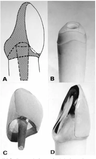
What, then, are the best post designs? What designs ensure the most retention? It turns out, as one might suspect, that threaded posts are Figure 10-1 Fauchard’s description, in the year 1728, of his attempts to restore single and multiple units. A,“Pivot tooth,” consisting of a crown, post, and assembled unit. B,Six-unit anterior bridge “pivoted” in pulpless lateral incisors with the canines cantilevered. Crowns were fashioned from a diversity of mate-rials: human, hippopotamus, and ox teeth, as well as ivory and leg bones. Posts were precious metal and were fastened to the crown with a sticky mastic. Nothing was said about treating the root canals before “cementation.”
Restoration of Endodontically Treated Teeth 263
the most retentiveand tapered posts are the least retentive. However, threaded posts produce the greatest potential for root fracture. Threaded posts that cut their own threads into the dentin are the most threatening, even when the post is a split post. Threaded posts that fit into counterthreads prepared in the dentin are less threatening. Parallel-sided posts with serrationsare more retentive than are smooth-sided parallel posts, and if they fit well in the canal, they are the least likely to cause fracture. Posts that do not fit well and “float in a sea of cement” gradually lose retention. Also, caries attack the root facing if the post loosens and allows space to develop under the core. Figure 10-2 One hundred twenty years after Fauchard, Tomes, in England, was advocating a more sophisticated form of post-and-crown construction.
Principles used today in selecting post length and diameter were taught by practitioners in the mid-1800s.
POST LENGTH
The rule of thumb for the proper length for a postisthree-quarters the length of the rootwhen treating long-rooted teeth. When an aver-age root length is encountered, post length should be dictated by retaining 5 mmof apical gutta-percha and extending the post to the gutta-percha (Figure 10-4A). In curved roots the post should ter-minate at the point where substantive curvature begins. Posts too shortare not retentive enough to withstand the forces of mastica-tion (Figure 10-4B), and posts too gross do not increase retenmastica-tion and they materially weakenthe tooth, leading to root fracture (Figure 10-5). Post diameter should not exceed one-third of the root diam-eter.
Laboratory testing and clinical observation have led to the con-clusion that 4 to 5 mm of gutta-perchashould remain in the apical canal, 5 mm being preferable (see Figure 10-4A). It makes no dif-ference if gutta-percha is removed at the time of canal filling com-pletion or at a subsequent appointment. When 5 mm of gutta-percha is retained, a rotary and/or heated instrument appears to be accept-able in removing the excess gutta-percha.
Figure 10-3 Fractured maxillary first premolar caused by a post with excessive diameter and insufficient length.
Restoration of Endodontically Treated Teeth 265
To avoid perforations and because of their familiarity with the canal direction and size, endodontists are now being asked more fre-quently to prepare post space and even to cement the post to place. In doing so the endodontist is assuming part of the risk in the even-tual failure of the case. It is therefore imperative that one knows well Figure 10-4 A,Five millimeters of gutta-percha root filling were retained in the maxillary premolar with a post extended to that point. B,Very short post in the distal root of the first molar has loosened and caused prosthesis failure.
A
the capabilities of the referring dentist and has a definite under-standing of the type of post to be placed. One caveat is that silver point fillings should be removed and replaced with adequately con-densed gutta-percha.
FERRULES
As stated above, one of the principal causes of failure is root frac-ture. A principal factor in preventing root fractureis the placement of a cervical ferrule, a circumferential band of metal that surrounds the neck of the preparation. Two types of ferrules can be construct-ed: ferrules that are part of the post, that is, cast metal ferrules, and those that are part of the crown. It has been found that ferrules formed as part of the post are less effective than ferrules created when the overlying crown engages the tooth structure. In short, crown fer-rules are more effective than post ferfer-rules. It has also been noted that ferrules that grasp a larger amount of tooth structure are more effec-tive than those that engage only a small amount of tooth structure (Figure 10-6).
Figure 10-5 The excessive post diameter in the maxillary second premolar cre-ated a perforation in the mesial root concavity. Note the distinct border and round shape of the radiolucent lesion, a characteristic form indicative of root perforation.
Restoration of Endodontically Treated Teeth 267
Figure 10-6 Excellent example of a crown ferrule that is extensive enough to strengthen the post crown in place. Courtesy of A.L. Frank.
TYPE OF POST AND CORE
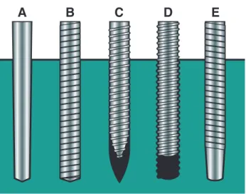
Posts or dowels can generally be classified as cemented/bonded posts and threaded posts. For retention, cemented posts depend on their close proximity to the dentin walls and the cementing medium used. Variations are custom-made (cast) posts and cores, and prefabri-cated posts, either tapered, smooth metal posts (Figure 10-7A) or parallel-sided metal posts (Para-Post, Coltene/Whaledent, Mahwah, NJ) (Figure 10-7B). Other than metal posts there are also ceramic posts made of zirconium dioxide, posts made of carbon fibers and reinforced polymers, and white fiberglass/composite posts that do not show through translucent crowns (White C-I posts, Parkell Co., Farmingdale, NY) (Figure 10-8).
There are two types of threaded posts:(1) tapered, self-threading posts, that is, posts that are screwed into the dentin that cut their own threads into the dentin (Figure 10-7C); and (2) posts that thread into pretapped counterthreadsprepared in the dentin (Kurer posts, Figure 10-7D). In addition, there are tapered, finely threaded posts (Figure 10-7E) and tapered, coarsely threaded “split” posts (Figure 10-9).
Figure 10-7 Prefabricated post designs. A,Tapered, smooth. B,Parallel, ser-rated. C,Tapered, self-threading. D,Parallel, threaded. Note that the post fits into pretapped threads cut into the dentin. E,Parallel, serrated, tapered end.
Restoration of Endodontically Treated Teeth 269
Figure 10-8 White C-I glass fiber/composite post (Parkell Co.) that does not show through metal-free translucent crowns.
Figure 10-9 Flexi Post (EDS Co.). Note the “split” in the apical portion of the post that permits some flexion during placement.
Most of these threaded posts stress the dentin because they screw into it, much as a wood screw can stress and split wood. The least threatening of all these threaded posts is the Kurer postbecause it does not stress the dentin. For Kurer posts the counterthreads are “tapped” into the dentin with a special instrument, and the threads of the post fit like a bolt into a nut, not like a screw into wood. In contrast, tapered, threaded postsadd additional stress on root struc-ture, and tapered, split postshave not been shown to provide any advantage over nonsplit types.
PREPARATION OF A POST AND CORE
For illustration, one type of post-and-core restoration is outlined here: the metal, parallel, serrated Para-Post (Figure 10-10). It is assumed that the root canal filling has been completed.
First the coronal tooth preparation is done (Figure 10-11A). The amount of tooth structure that needs to be removed is related to
Figure 10-10 Para-Post (Coltene/Whaledent) is a parallel-sided, vented, ser-rated post (right).The canal is enlarged with a Peeso reamer (left),and the final channel preparation is made with a matched twist drill (center).
Restoration of Endodontically Treated Teeth 271
the type of crown to be placed. The chamfer for the ferrule is estab-lished. If some of the tooth structure is very thin, it is best to remove it and replace it with the core material.
Pulp Chamber Preparation
The best time to prepare the post space is when the root canal fill-ing is completed. For this, Peeso drills and a twist drill matched to the size of the post to be placed are used (see Figure 10-10). First the extra gutta-percha is removed with a warm plugger (Figure 10-11B). Remember, 5 mm of gutta-percha is to be left in the apical area, so any removal instruments should have a rubber stop placed so as not to exceed this depth. Next advancing sizes of Peeso drills are used in a slow-speed handpiece until the required depth is reached and the dentin walls are enlarged to near the size of the post to be placed (Figure 10-11C). Then the Para-Post twist drill the same size of the post that is to follow is used to refine the space (Figure 10-11D). Figure 10-11 Placement of the parallel-sided Para-Post (Coltene/Whaledent) and composite resin core in an anterior tooth. A,Endodontic treatment com-pleted. B,Gutta-percha removed. C,Post space formed with Peeso drill. D,
Post space refined with Para-Post twist drill. E,Trial placement of the post. F,
Shortening the post so it does not interfere with occlusal closure but with space for fabrication of the core. The post is cemented after shortening. G,The tooth is etched and the bonded-composite core is formed and shaped with rotary instruments.
Next is the trial placement of the post to verify approximation with-out binding (Figure 10-11E). It should be measured or radiographed to make sure it is at full depth, that is, up against the remaining gutta-percha. The post should then be shortened so that it does not inter-fere with closure and there will be enough space for the fabrication of the crown (Figure 10-11F). Before it is cemented to place, it has been suggested that the smear layer be removed from the dentin walls with a rinse of NaOCl and MTAD (ProRoot MTAD, Dentsply/Tulsa Dental). Finally, the post is cemented to place and the core is built up to receive the final restoration (Figure 10-11G).
OVERDENTURES
In 1789 George Washington’s first lower denture, constructed of ivory by John Greenwood, was in part supported by a left mandibu-lar premomandibu-lar. In 1969 Lord and Teel coined the term “overdenture” and described the combined endodontic-periodontic-prosthodontic technique applied thereto.1The concept of retaining roots in the alve-olar process is based on the proven observation that as long as the root remains, the bone surrounding it remains (Figure 10-12). This
Figure 10-12 Overdenture abutment, well obturated and restored with amalgam. Note the excellent bony support. Courtesy of D.H. Wands.
Restoration of Endodontically Treated Teeth 273
overcomes the age-old prosthetic problem of ridge resorption (Figure 10-13). Ideally, retaining four teeth, two molars and two canines, one each at the four divergent points of the arch, should provide good balance and long life to a full overdenture (Figure 10-14).
If the abutment teeth are reduced to a short, rounded or bullet shape—literally tucking the abutment inside the denture base—the crown-root ratio of the tooth is vastly improved, especially for peri-odontally involved teeth that have lost some bone support (Figure 10-15).
Figure 10-13 Dramatic demonstration of alveolar bone remaining around retained canines but badly resorbed under a full upper and a posterior lower partial. Courtesy of J.L. Lord and S. Teel.
Figure 10-14 Four retained abutments providing ideal support for an overden-ture. Courtesy of A.A. Brewer and R.M. Morrow.
It goes without saying that root canal treatment is necessary for these abutment teeth. The crowns of the teeth are amputated 3 to 4 mm above the gingival level. The length of the remaining tooth is accurately established, and the pulps are removed. The canals are then cleaned and shaped, the smear layer is removed, and the canals are obturated with sealer and gutta-percha. Next the coronal 3 to 5 mm of the gutta-percha filling is removed, the preparation is under-cut, and an amalgam filling is placed with bonded sealer (AmalgamBond, Parkell Co., Farmingdale, NY).
The abutments should then be properly bullet shaped with a slope back from the labial aspect to accommodate the denture tooth to be set above it. The abutments must not be too short or tissue will grow over them as “lawn grows over a sidewalk.” The abutments, tooth, and amalgam are then highly polished. When the denture is ready to be seated, it is relieved over the abutment areas, and a small amount of self-curing acrylic is placed in the relieved areas (Figure 10-16). This ensures a perfect fit over the abutments.
Figure 10-15 Mandibular canines that have served as overdenture abutments for years. Courtesy of A. Fenton and A.A. Brewer.
Restoration of Endodontically Treated Teeth 275
OVERDENTURE PROBLEMS
Most overdenture problems relate to poor patient care. Patients who have been neglectful of their teeth throughout their lifetime can hardly be considered prime candidates for the good hygiene in the future. Recall appointments and bathing the teeth with sodium fluoride can be of some help. After all, two or four abutments should not be too hard to keep clean.
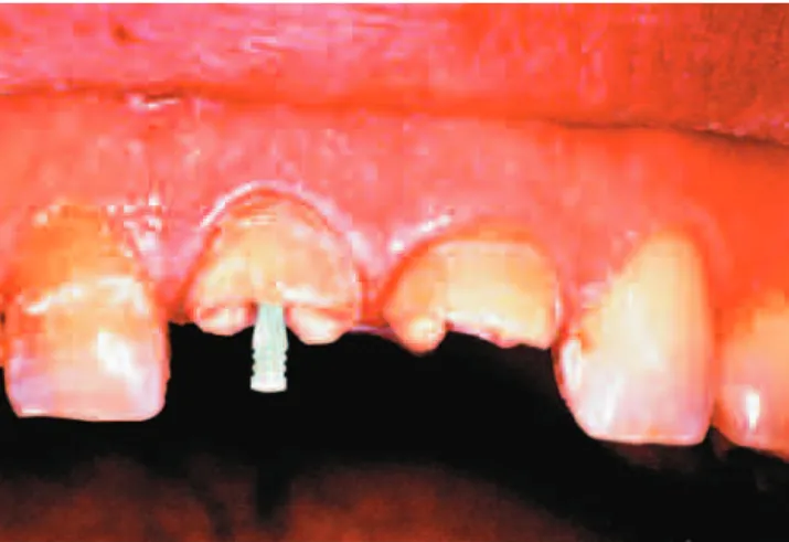
Another problem is retention.Fortunately, there is a solution to the retention problem. The Locator Overdenture Attachment(Zest Anchors, Escondido, CA) has emerged as a remarkably clever solu-tion to this age-old problem. The self-locating design allows patients to easily seat their overdenture. The post of the female attachment that fits in the endodontic tooth comes in three designs: a straight post and 10° and 20° posts to accommodate divergent roots (Figure 10-17).2The Locator Attachment is a parallel post that is notched for retention. It has a length of 6 mm but can be shortened to as little as 3 mm. It is stainless steel with a titanium nitride coating and is passively cemented in place, not threaded or screwed into the root. Figure 10-16 Soft, self-curing acrylic fills the depression prepared in the den-ture to receive the abutment. This may be replaced whenever necessary.
Figure 10-18 Four Locator Overdenture Attachments (Zest Anchors) ensure adequate retention for a mandibular full denture. Courtesy of A.L. Schneider.
The canal is first prepared with a Locator pilot drill to the select-ed depth. This is followselect-ed by a countersink diamond bur that forms a shallow recessed seat in the flat root surface. At least 1.5 mm of the female attachment must rise above the gingival crest to allow the male component in the denture to snap into place. The combined Locator attachment connection rises only 2.5 mm above the root face (Figure 10-18).3
Figure 10-17 A,Locator Overdenture Attachments (Zest Anchors). Female attachments to be cemented into endodontically treated teeth: 0°(left);10°
(center);20°(right).B,Illustration of how verticality and parallelism can be achieved with a 20° female attachment in a tooth abutment with divergent roots.
Restoration of Endodontically Treated Teeth 277
The male attachment,which is processed in the denture, is stain-less steel and is fitted with a nylon insert that allows the metal cap to pivot up to 7° without contacting the surface of the root. This allows some flexibility in the denture movement, which allows the patient to easily self-align the denture over the attachments and snap it into position (Figure 10-19). The nylon insert snaps into the female attachment much like a clothes “gripper” or, as the British call it, a press-stud. The nylon inserts also come in three strengths: 2.3 kg (5 lb.) for strong retention, 1.4 kg (3 lb.) for medium retention, and 0.7 kg (1.5 lb.) for light retention. When it comes to removing the den-ture, older or arthritic patients may find the light retention easier to manage. Husky males may prefer to have strong retention inserts. As the nylon inserts wear, they may easily be pried from position and a fresh insert snapped to place.
Locator attachments are also made for osseointegrated implant overdentures.
Figure 10-19 The male Locator Overdenture Attachment (Zest Anchors), which is implanted in the denture, is stainless steel with a snap-in plastic insert that, in turn, snaps into the female attachment below. A,The male attachment moving into place. B,The attachment positioned over the female receptacle. C,The male attachment snapped into place. When the plastic inserts wear, they may be pried out of the attachment and replaced with new nylon inserts. The plastic allows movement in the denture.
REFERENCES
1. Lord JL, Teel S. The overdenture. Dent Clin North Am 1969;13:871. 2. Pavlatos J. The root-supported overdenture using the Locator overdenture
attachment. Gen Dent 2002;Sept./Oct:448.
3. Schneider AL. The use of self-aligning, low-maintenance overdenture attach-ment. Dent Today 2000;19.