®
525B
Temperature/Pressure Calibrator
Getting Started Guide
PN 3064079 October 2007
LIMITED WARRANTY AND LIMITATION OF LIABILITY
Each Fluke product is warranted to be free from defects in material and workmanship under normal use and service. The warranty period is one year and begins on the date of shipment. Parts, product repairs, and services are warranted for 90 days. This warranty extends only to the original buyer or end-user customer of a Fluke authorized reseller, and does not apply to fuses, disposable batteries, or to any product which, in Fluke's opinion, has been misused, altered, neglected, contaminated, or damaged by accident or abnormal conditions of operation or handling. Fluke warrants that software will operate substantially in accordance with its functional specifications for 90 days and that it has been properly recorded on non-defective media. Fluke does not warrant that software will be error free or operate without interruption.
Fluke authorized resellers shall extend this warranty on new and unused products to end-user customers only but have no authority to extend a greater or different warranty on behalf of Fluke. Warranty support is available only if product is purchased through a Fluke authorized sales outlet or Buyer has paid the applicable international price. Fluke reserves the right to invoice Buyer for importation costs of
repair/replacement parts when product purchased in one country is submitted for repair in another country. Fluke's warranty obligation is limited, at Fluke's option, to refund of the purchase price, free of charge repair, or replacement of a defective product which is returned to a Fluke authorized service center within the warranty period.
To obtain warranty service, contact your nearest Fluke authorized service center to obtain return authorization information, then send the product to that service center, with a description of the difficulty, postage and insurance prepaid (FOB Destination). Fluke assumes no risk for damage in transit. Following warranty repair, the product will be returned to Buyer, transportation prepaid (FOB Destination). If Fluke determines that failure was caused by neglect, misuse, contamination, alteration, accident, or abnormal condition of operation or handling, including overvoltage failures caused by use outside the product’s specified rating, or normal wear and tear of mechanical components, Fluke will provide an estimate of repair costs and obtain authorization before commencing the work. Following repair, the product will be returned to the Buyer transportation prepaid and the Buyer will be billed for the repair and return transportation charges (FOB Shipping Point).
THIS WARRANTY IS BUYER'S SOLE AND EXCLUSIVE REMEDY AND IS IN LIEU OF ALL OTHER WARRANTIES, EXPRESS OR IMPLIED, INCLUDING BUT NOT LIMITED TO ANY IMPLIED WARRANTY OF MERCHANTABILITY OR FITNESS FOR A PARTICULAR PURPOSE. FLUKE SHALL NOT BE LIABLE FOR ANY SPECIAL, INDIRECT, INCIDENTAL, OR CONSEQUENTIAL DAMAGES OR LOSSES,
INCLUDING LOSS OF DATA, ARISING FROM ANY CAUSE OR THEORY.
Since some countries or states do not allow limitation of the term of an implied warranty, or exclusion or limitation of incidental or consequential damages, the limitations and exclusions of this warranty may not apply to every buyer. If any provision of this Warranty is held invalid or unenforceable by a court or other decision-maker of competent jurisdiction, such holding will not affect the validity or enforceability of any other provision. Fluke Corporation P.O. Box 9090 Everett, WA 98206-9090 U.S.A. Fluke Europe B.V. P.O. Box 1186 5602 BD Eindhoven The Netherlands
Table of Contents
Title
Page
Introduction... 1
Contacting Fluke... 1
Standard Equipment... 2
Options and Accessories... 2
Safety Information ... 2
Getting Acquainted with the Calibrator... 4
Input and Output Terminals... 4
Display Error Messages... 8
Rear Panel View ... 9
General Specifications ... 10
Electrical Specifications ... 10
DC Voltage Specifications, Output ... 10
DC Current Specifications, Output... 11
Resistance Specifications, Output ... 11
Resistance Specifications, Input... 11
Thermocouple Specification, Output and Input ... 12
RTD and Thermistor Specification, Output ... 13
RTD and Thermistor Specification, Input ... 14
List of Tables
Table Title
Page
1.
Summary of Input and Output Functions... 1
2.
Symbols Used on the Calibrator... 3
3. Function
Keys ...
6
List of Figures
Figure
Title
Page
1.
Input and Output Terminals and Connectors ... 4
2. Pushbuttons ...
5
3.
Calibrator Function Keys ... 6
Temperature/Pressure Calibrator
Introduction
Your Fluke 525B Temperature/Pressure Calibrator (referred to as the Calibrator) is an
instrument designed to meet the demands of your process tools calibration workload.
In addition to the functions in Table 1, the Calibrator has the following features and
functions.
•
Two line backlit LCD display
•
5-way binding posts
•
IEEE 488.2 parallel
•
RS-232 serial interface
Contacting Fluke
To order accessories or get the location of the nearest Fluke distributor or Service Center,
call:
•
USA: 1-888-99-FLUKE (1-888-993-5853)
•
Canada: 1-800-36-FLUKE (1-800-363-5853)
•
Europe: +31-402-678-200
•
Japan: +81-3-3434-0181
•
Singapore: +65-738-5655
•
Anywhere in the world: +1-425-446-5500
Or, visit Fluke’s Web site at
www.fluke.com
.
To register your product, visit
register.fluke.com
.
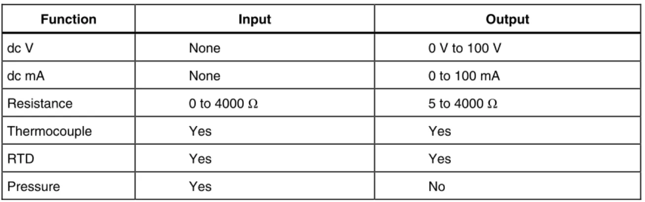
Table 1. Summary of Input and Output Functions
Function Input Output
dc V None 0 V to 100 V
dc mA None 0 to 100 mA
Resistance 0 to 4000 Ω 5 to 4000 Ω
Thermocouple Yes Yes
RTD Yes Yes
Standard Equipment
The items listed below are included with your Calibrator. If the Calibrator is damaged or
something is missing, contact the place of purchase immediately. For information on
replacement parts or spares, see the replacement parts list in Chapter 6 of the
525B Users
Manual
.
•
525B Getting Started Guide
(this document), Part No. 3064079
•
525B CD-ROM (contains the
525B
Users Manual
and
525B
Getting Started Guide
),
Part No. 3064087
•
Power Cord (120 V cord, Part No. 1618621 or 240 V cord, Part No. 769422)
•
Thermocouple Shorting Jumper, Part No. 610747
Options and Accessories
For more information about these accessories and their prices, contact your Fluke
representative.
•
5520A – 525A Leads kit
•
Y525 Rack Mount kit
•
Fluke 700 and 525A-P series pressure modules
•
MET/CAL with 525B Function Select Code (FSC)
•
MET/CAL 525B calibration procedure
Safety Information
This Calibrator complies with IEC 61010, ANSI/ISA-S82.01-1994, CAN/CSA-C22.2
No. 1010.1-92. Use the Calibrator only as specified in this manual, otherwise the
protection provided by the Calibrator may be impaired.
CAT II
equipment is designed to protect against transients from energy-consuming
equipment supplied from the fixed installation, such as TVs, PCs, portable tools, and
other household appliances.
A
Warning
statement identifies hazardous conditions and actions that could cause bodily
harm or death.
A
Caution
statement identifies conditions and actions that could damage the Calibrator
or the equipment under test.
Temperature/Pressure Calibrator
Safety InformationW
Warning
To avoid possible electric shock or personal injury, follow these guidelines:
•
Use the Calibrator only as specified in this manual, or the protection provided by the
Calibrator might be impaired.
•
Inspect the Calibrator before using it. Do not use the Calibrator if it appears
damaged. Look for cracks or missing plastic. Pay particular attention to the
insulation around the connectors.
•
Have the Calibrator serviced only by qualified service personnel.
•
Do not apply more than the rated voltage, as marked on the Calibrator, between the
terminals or between any terminal and earth ground.
•
Always use the power cord and connector appropriate for the voltage and outlet of
the country or location in which you are working.
•
Never operate the Calibrator with the cover removed or the case open.
•
Never remove the cover or open the case of the Calibrator without first removing the
power source.
•
Use caution when working with voltages above 30 V ac rms, 42 V ac peak, or
60 V dc. These voltages pose a shock hazard.
•
Use only the replacement fuse(s) specified in this manual.
•
Use the proper terminals, function, and range for your measurements.
•
Do not operate the Calibrator around explosive gas, vapor, or dust.
•
When servicing the Calibrator, use only specified replacement parts.
Table 2. Symbols Used on the Calibrator
B
AC (Alternating Current).J
Earth ground.F
DC (Direct Current).e
Resistance.f
Pressure.P
Conforms to European Uniondirectives.
Chassis protective ground.
)
Canadian Standards Association,NRTL.
W
Important Information. See manual.+
International ON/OFF symbol.X
Hazardous voltage. Risk ofGetting Acquainted with the Calibrator
Input and Output Terminals
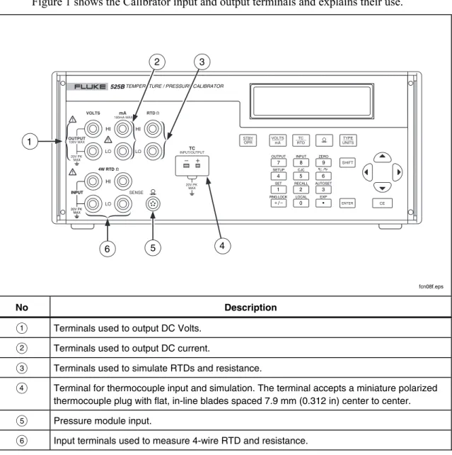
Figure 1 shows the Calibrator input and output terminals and explains their use.
INPUT OUTPUT HI VOLTS mA RTD HI LO HI LO LO TC SENSE INPUT/OUTPUT 4W RTD SET RECALL LOCAL EXP AUTOSET INPUT OUTPUT ZERO RNG LOCK C / F CJC SETUP 20V PK MAX 100V MAX 100mA MAX 20V PK MAX 20V PK MAX
525BTEMPERATURE / PRESSURE CALIBRATOR
0 • 1 2 3 4 5 6 7 8 9 / VOLTS mA TYPE UNITS TC RTD CE SHIFT STBY OPR ENTER 4 3 2 5 6 1 fcn08f.eps No Description
A
Terminals used to output DC Volts.B
Terminals used to output DC current.C
Terminals used to simulate RTDs and resistance.D
Terminal for thermocouple input and simulation. The terminal accepts a miniature polarized thermocouple plug with flat, in-line blades spaced 7.9 mm (0.312 in) center to center.E
Pressure module input.F
Input terminals used to measure 4-wire RTD and resistance.Temperature/Pressure Calibrator
Getting Acquainted with the CalibratorUsing the Keys
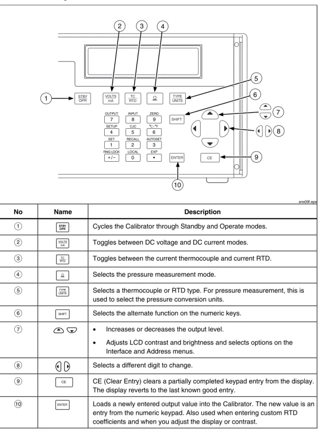
Figure 2 shows the Calibrator pushbuttons and explains their use. Other function keys are
shown in Figure 3 and described in Table 3.
SET RECALL LOCAL EXP AUTOSET INPUT OUTPUT ZERO RNG LOCK C / F CJC SETUP 0 • 1 2 3 4 5 6 7 8 9 / VOLTS mA TYPE UNITS TC RTD SHIFT ENTER STBY OPR CE 1 4 3 2 8 5 6 9 10 7 ans09f.eps No Name Description
A
A
Cycles the Calibrator through Standby and Operate modes.B
B
Toggles between DC voltage and DC current modes.C
C
Toggles between the current thermocouple and current RTD.D
D
Selects the pressure measurement mode.E
E
Selects a thermocouple or RTD type. For pressure measurement, this isused to select the pressure conversion units.
F
I
Selects the alternate function on the numeric keys.G
M O
• Increases or decreases the output level.• Adjusts LCD contrast and brightness and selects options on the Interface and Address menus.
H
L N
Selects a different digit to change.I
F
CE (Clear Entry) clears a partially completed keypad entry from the display.The display reverts to the last known good entry.
J
J
Loads a newly entered output value into the Calibrator. The new value is anentry from the numeric keypad. Also used when entering custom RTD coefficients and when you adjust the display or contrast.
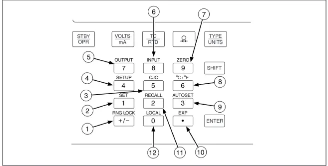
SET RECALL LOCAL EXP AUTOSET INPUT OUTPUT ZERO RNG LOCK C / F CJC SETUP 0 • 1 2 3 4 5 6 7 8 9 / 7 11 10 5 4 3 1 2 8 9 12 6 VOLTS mA TYPE UNITS TC RTD SHIFT ENTER STBY OPR ans11f.eps Figure 3. Calibrator Function Keys
Table 3. Function Keys
No Name Description
A
RNG LOCKG
Activates/deactivates the autorange feature of the Calibrator in Voltage source modes.B
SET1
Used to program a setpoint step for any output mode.Key in the desired output and press I1. SETPOINT # appears on the display. Select a setpoint number from 1 to 9. The output you entered can now be recalled or used in the AUTOSET key described later in this manual.
Each TC type, each RTD/OHMS type, mA, and Volts each have 9 programmable setpoints.
C
CJC5
Toggles between the internal and external cold junction reference locations.D
SETUPTemperature/Pressure Calibrator
Getting Acquainted with the CalibratorTable 3. Function Keys (cont)
No Name Description
F
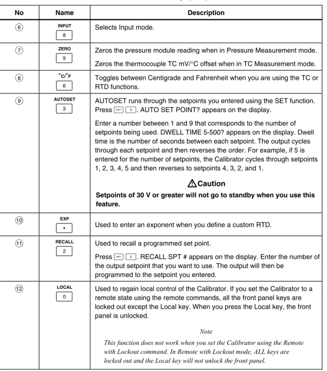
INPUT8
Selects Input mode.G
ZERO9
Zeros the pressure module reading when in Pressure Measurement mode.Zeros the thermocouple TC mV/°C offset when in TC Measurement mode.
H
°C/°F6
Toggles between Centigrade and Fahrenheit when you are using the TC or RTD functions.I
AUTOSET3
AUTOSET runs through the setpoints you entered using the SET function. Press I3. AUTO SET POINT? appears on the display. Enter a number between 1 and 9 that corresponds to the number of setpoints being used. DWELL TIME 5-500? appears on the display. Dwell time is the number of seconds between each setpoint. The output cycles through each setpoint and then reverses the order. For example, if 5 is entered for the number of setpoints, the Calibrator cycles through setpoints 1, 2, 3, 4, 5 and then reverses to setpoints 4, 3, 2, and 1.W
Caution
Setpoints of 30 V or greater will not go to standby when you use this feature.
J
EXPH
Used to enter an exponent when you define a custom RTD.K
RECALL2
Used to recall a programmed set point.Press I2. RECALL SPT # appears on the display. Enter the number of the output setpoint that you want to use. The output will then be
programmed to the setpoint you entered.
L
LOCAL0
Used to regain local control of the Calibrator. If you set the Calibrator to a remote state using the remote commands, all the front panel keys are locked out except the Local key. When you press the Local key, the front panel is unlocked.Note
This function does not work when you set the Calibrator using the Remote with Lockout command. In Remote with Lockout mode, ALL keys are locked out and the Local key will not unlock the front panel
.
Display Error Messages
The following informative messages may appear on the front panel display. An
explanation of each message is also provided.
Table 4. Display Error Messages
Message Explanation
OVER RANGE May be displayed in all output modes if you enter a value from the front
panel keypad that exceeds the output range of the function.
OVER LOAD May be displayed in V and mA output modes when the current is exceeded
for volts and the resistance is exceeded for mA.
OL Displayed in Input modes when the measured value exceeds the upper
limit of the range.
This error may also display in Output mode when the range is locked and an automatically recalled set point exceeds the locked range. For example, set point 1 (SP1) is set to 1V, SP2 is set to 2V, and SP3 is set to 100V, the range is locked to 10V range and the Calibrator is set up to automatically output the first 3 setpoints. When the Calibrator reaches SP3, the display reads OL, and the output is set to 0 for the duration of that setpoint.
-OL Displayed in Input modes when the measured value exceeds the lower
limit of the range.
Temperature/Pressure Calibrator
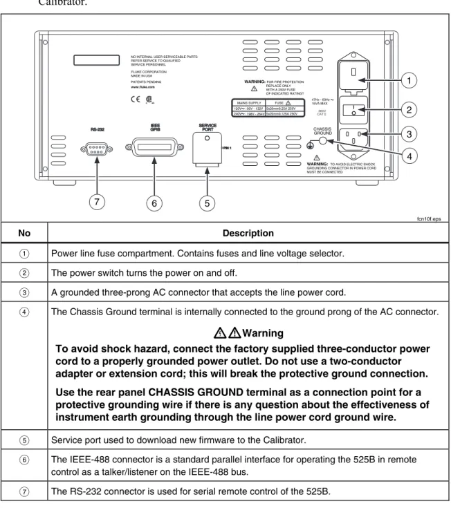
Getting Acquainted with the CalibratorRear Panel View
Figure 4 shows the rear panel and explains the use of the rear panel features of the
Calibrator.
WARNING: FOR FIRE PROTECTION
REPLACE ONLY WITH A 250V FUSE OF INDICATED RATING? CHASSIS GROUND 47Hz - 63Hz 15VA MAX FLUKE CORPORATION MADE IN USA www.fluke.com PATENTS PENDING
NO INTERNAL USER SERVICEABLE PARTS REFER SERVICE TO QUALIFIED SERVICE PERSONNEL
WARNING: TO AVOID ELECTRIC SHOCK GROUNDING CONNECTOR IN POWER CORD MUST BE CONNECTED
300V
CAT
C US MAINS SUPPLY FUSE 120V: 90V - 132V : 198V - 264V 240V 5x20mm0.25A 250V 5x20mm0.125A 250V 7 6 5 1 2 3 4 fcn10f.eps No Description
A Power line fuse compartment. Contains fuses and line voltage selector.
B The power switch turns the power on and off.
C A grounded three-prong AC connector that accepts the line power cord.
D The Chassis Ground terminal is internally connected to the ground prong of the AC connector.
XW
Warning
To avoid shock hazard, connect the factory supplied three-conductor power
cord to a properly grounded power outlet. Do not use a two-conductor
adapter or extension cord; this will break the protective ground connection.
Use the rear panel CHASSIS GROUND terminal as a connection point for a
protective grounding wire if there is any question about the effectiveness of
instrument earth grounding through the line power cord ground wire.
E Service port used to download new firmware to the Calibrator.
F The IEEE-488 connector is a standard parallel interface for operating the 525B in remote control as a talker/listener on the IEEE-488 bus.
G The RS-232 connector is used for serial remote control of the 525B.
General Specifications
Warm up time... Twice the time since last warmed up, to a maximum of 30 minutes.
Settling time... Less than 5 seconds for all functions and ranges except as noted.
Standard interface... RS-232, IEEE-488 (GPIB)
Temperature performance
Operating ... 0 °C to 50 °C Calibration (tcal)... 18 °C to 28 °C Storage ... -20 °C to 70 °C
Electromagnetic compatibility... CE: Conforms to EN61326
Temperature coefficient... Temperature coefficient for temperatures outside tcal ± 5 °C is 10 % of the 90 day specification (or 1 year if applicable) per °C
Relative humidity Operating ... < 80 % to 30 °C, < 70 % to 40 °C, < 40 % to 50 °C Storage ... < 95 % noncondensing Altitude Operating ... 3,050 m (10,000 ft) maximum Nonoperating ... 12,200 m (40,000 ft) maximum
Safety... EN 61010 Second, ANSI/ISA-S82.01-1994, CAN/CSA-C22.2 No. 1010.1-92, NRTL
Analog low isolation... 20 V
Line power
Line Voltage (selectable) ... 100 V/120 V or 220 V/240 V Line Frequency ... 47 to 63 Hz
Line Voltage Variation...± 10 % about line voltage setting
Power consumption... 15 VA maximum
Dimensions
Height... 13.3 cm (5.25 in) plus 1.5 cm (0.6 in) four feet on bottom Width... ¾ standard rack width
Depth ... 47.3 cm (18.6 in) overall
Weight (without options)... 4 kg (9 lb)
Electrical Specifications
DC Voltage Specifications, Output
Absolute Uncertainty, tcal ± 5 °C
± (ppm of output + μV)
Stability
Ranges[1]
90 days 1 year 24 hours, ± 1 °C
± (ppm of output + μV)
Resolution Maximum Burden[2]
Temperature/Pressure Calibrator
Electrical Specifications Noise Ranges Bandwidth 0.1 to 10 Hz ± (ppm of output + μV p-p) Bandwidth 10 Hz to 10 kHz (μV rms) 0 to 100.000 mV 1 μV 6 μV 0 to 1.00000 V 10 μV 60 μV 0 to 10.0000 V 100 μV 600 μV 0 to 100.000 V 10 ppm+1 mV 20 mVDC Current Specifications, Output
Absolute Uncertainty
tcal ± 5 °C ± (ppm of output + mA)
Ranges[1] 90 days 1 year Resolution Maximum Compliance Voltage Maximum Inductive Load 0 to 100.000 mA 40 1 50 1 1 μA 12 V 100 mH Note:
[1] All outputs are positive only.
Noise Ranges Bandwidth 0.1 to 10 Hz p-p Bandwidth 10 Hz to 10 kHz rms 0 to 100.000 mA 2000 nA 20 μA
Resistance Specifications, Output
Absolute Uncertainty tcal ± 5°C, ±Ω
Ranges[1]
90 days 1 year
Resolution Allowable Current[2]
5 to 400.00 Ω 0.012 0.015 0.001 Ω 1 to 3 mA
5 to 4.0000 kΩ 0.25 0.3 0.01 Ω 100 μA to 1 mA
Notes:
[1] Continuously variable from 0 to 4 kΩ.
[2] For currents lower than shown, the floor adder increases by Floor(new) = Floor(old) x Imin/Iactual. For example, a 500 μA stimulus measuring 100 Ω has a floor uncertainty of 0.015 Ω x 1 mA/500 μA = 0.03 Ω.
Resistance Specifications, Input
Absolute Uncertainty tcal ± 5°C, ± (ppm of output + Ω)
Ranges[1]
90 days 1 year
Resolution Stimulus Current
5 to 400.00 Ω 20 0.0035 20 0.004 0.001 Ω 1 mA
5 to 4.00000 kΩ 20 0.0035 20 0.004 0.01 Ω 0.1 mA
Note:
Thermocouple Specification, Output and Input
Absolute Uncertainty tcal ± 5 °C, ± (°C)[1] Range (°C) Output/Input TC TypeMinimum Maximum 90 days 1 year
B 600 °C 800 °C 1000 °C 1550 °C 800 °C 1000 °C 1550 °C 1820 °C 0.42 °C 0.39 °C 0.40 °C 0.44 °C 0.46 °C 0.39 °C 0.40 °C 0.45 °C C 0 °C 150 °C 650 °C 1000 °C 1800 °C 150 °C 650 °C 1000 °C 1800 °C 2316 °C 0.25 °C 0.21 °C 0.23 °C 0.38 °C 0.63 °C 0.30 °C 0.26 °C 0.31 °C 0.50 °C 0.84 °C E -270 °C -100 °C -25 °C 350 °C 650 °C -100 °C -25 °C 350 °C 650 °C 1820 °C 0.38 °C 0.16 °C 0.14 °C 0.14 °C 0.16 °C 0.50 °C 0.18 °C 0.15 °C 0.16 °C 0.21 °C J -270 °C -100 °C -25 °C 120 °C 1000 °C -100 °C -30 °C 150 °C 760 °C 1200 °C 0.20 °C 0.18 °C 0.14 °C 0.14 °C 0.18 °C 0.27 °C 0.20 °C 0.16 °C 0.17 °C 0.23 °C K -270 °C -100 °C -25 °C 120 °C 1000 °C -100 °C -25 °C 120 °C 1000 °C 1372 °C 0.25 °C 0.19 °C 0.14 °C 0.19 °C 0.30 °C 0.33 °C 0.22 °C 0.16 °C 0.26 °C 0.40 °C L -200 °C -100 °C 800 °C -100 °C 800 °C 900 °C 0.37 °C 0.26 °C 0.17 °C 0.37 °C 0.26 °C 0.17 °C N -270 °C -100 °C -25 °C 120 °C 410 °C -100 °C -25 °C 120 °C 410 °C 1300 °C 0.33 °C 0.20 °C 0.16 °C 0.14 °C 0.21 °C 0.40 °C 0.24 °C 0.19 °C 0.18 °C 0.27 °C R -50 °C 250 °C 400 °C 1000 °C 250 °C 400 °C 1000 °C 1760 °C 0.58 °C 0.34 °C 0.31 °C 0.30 °C 0.58 °C 0.35 °C 0.33 °C 0.40 °C S 0 °C 250 °C 1000 °C 1400 °C 250 °C 1000 °C 1400 °C 1750 °C 0.56 °C 0.36 °C 0.30 °C 0.35 °C 0.56 °C 0.36 °C 0.37 °C 0.46 °C T -270 °C -150 °C -150 °C 0 °C 0.51 °C 0.18 °C 0.63 °C 0.24 °C
Temperature/Pressure Calibrator
Electrical SpecificationsRTD and Thermistor Specification, Output
Range (°C) Absolute Uncertainty tcal ± 5 °C, ± (°C)[1]
RTD Type
Minimum Maximum 90 days 1 year
Pt 385, 100 Ω -200 °C -80 °C 0 °C 100 °C 300 °C 400 °C 630 °C -80 °C 0 °C 100 °C 300 °C 400 °C 630 °C 800 °C 0.03 °C 0.04 °C 0.04 °C 0.03 °C 0.04 °C 0.04 °C 0.04 °C 0.04 °C 0.05 °C 0.05 °C 0.04 °C 0.04 °C 0.05 °C 0.05 °C Pt 3926, 100 Ω -200 °C -80 °C 0 °C 100 °C 300 °C 400 °C -80 °C 0 °C 100 °C 300 °C 400 °C 630 °C 0.03 °C 0.03 °C 0.03 °C 0.03 °C 0.03 °C 0.04 °C 0.04 °C 0.04 °C 0.04 °C 0.04 °C 0.04 °C 0.05 °C Pt 3916, 100 Ω -200 °C -190 °C -80 °C 0 °C 100 °C 260 °C 300 °C 400 °C 600 °C -190 °C -80 °C 0 °C 100 °C 260 °C 300 °C 400 °C 600 °C 630 °C 0.03 °C 0.03 °C 0.03 °C 0.03 °C 0.03 °C 0.03 °C 0.03 °C 0.04 °C 0.04 °C 0.03 °C 0.04 °C 0.04 °C 0.04 °C 0.04 °C 0.04 °C 0.04 °C 0.05 °C 0.05 °C Pt 385, 200 Ω -200 °C -80 °C 0 °C 100 °C 260 °C 300 °C 400 °C 600 °C -80 °C 0 °C 100 °C 260 °C 300 °C 400 °C 600 °C 630 °C 0.31 °C 0.32 °C 0.33 °C 0.33 °C 0.36 °C 0.36 °C 0.42 °C 0.42 °C 0.38 °C 0.38 °C 0.39 °C 0.39 °C 0.43 °C 0.43 °C 0.50 °C 0.50 °C Pt 385, 500 Ω -200 °C -80 °C 0 °C 100 °C 260 °C 300 °C 400 °C 600 °C -80 °C 0 °C 100 °C 260 °C 300 °C 400 °C 600 °C 630 °C 0.13 °C 0.13 °C 0.13 °C 0.14 °C 0.14 °C 0.15 °C 0.16 °C 0.16 °C 0.15 °C 0.15 °C 0.16 °C 0.17 °C 0.17 °C 0.18 °C 0.19 °C 0.19 °C Pt 385, 1000 Ω -200 °C -80 °C 0 °C 100 °C 260 °C 300 °C 400 °C 600 °C -80 °C 0 °C 100 °C 260 °C 300 °C 400 °C 600 °C 630 °C 0.06 °C 0.06 °C 0.07 °C 0.07 °C 0.07 °C 0.07 °C 0.08 °C 0.08 °C 0.07 °C 0.08 °C 0.08 °C 0.08 °C 0.09 °C 0.09 °C 0.09 °C 0.09 °C Ni 120, 120 Ω -80 0 °°C C 100 °C 0 °C 100 °C 260 °C 0.02 °C 0.02 °C 0.01 °C 0.02 °C 0.02 °C 0.02 °C Cu 427, 10 Ω [2] -100 °C 260 °C 0.30 °C 0.38 °C YSI 400 15 °C 50 °C 0.005 °C 0.007 °C Notes: [1] 2-wire output.
RTD and Thermistor Specification, Input
Range (°C) Absolute Uncertainty tcal ± 5 °C, ± (°C)[1]
RTD Type
Minimum Maximum 90 days 1 year
Pt 385, 100 Ω -200 °C -80 °C 0 °C 100 °C 300 °C 400 °C 630 °C -80 °C 0 °C 100 °C 300 °C 400 °C 630 °C 800 °C 0.011 °C 0.018 °C 0.018 °C 0.027 °C 0.031 °C 0.042 °C 0.050 °C 0.012 °C 0.020 °C 0.020 °C 0.030 °C 0.035 °C 0.047 °C 0.057 °C Pt 3926, 100 Ω -200 °C -80 °C 0 °C 100 °C 300 °C 400 °C -80 °C 0 °C 100 °C 300 °C 400 °C 630 °C 0.011 °C 0.014 °C 0.018 °C 0.026 °C 0.031 °C 0.041 °C 0.011 °C 0.015 °C 0.019 °C 0.029 °C 0.034 °C 0.046 °C Pt 3916, 100 Ω -200 °C -190 °C -80 °C 0 °C 100 °C 260 °C 300 °C 400 °C 600 °C -190 °C -80 °C 0 °C 100 °C 260 °C 300 °C 400 °C 600 °C 630 °C 0.006 °C 0.011 °C 0.014 °C 0.018 °C 0.025 °C 0.026 °C 0.031 °C 0.040 °C 0.042 °C 0.006 °C 0.012 °C 0.015 °C 0.019 °C 0.028 °C 0.029 °C 0.034 °C 0.045 °C 0.047 °C Pt 385, 200 Ω -200 °C -80 °C 0 °C 100 °C 260 °C 300 °C 400 °C 600 °C -80 °C 0 °C 100 °C 260 °C 300 °C 400 °C 600 °C 630 °C 0.008 °C 0.012 °C 0.015 °C 0.020 °C 0.050 °C 0.053 °C 0.070 °C 0.071 °C 0.009 °C 0.013 °C 0.017 °C 0.022 °C 0.053 °C 0.057 °C 0.075 °C 0.076 °C Pt 385, 500 Ω -200 °C -80 °C 0 °C 100 °C 260 °C 300 °C 400 °C 600 °C -80 °C 0 °C 100 °C 260 °C 300 °C 400 °C 600 °C 630 °C 0.007 °C 0.019 °C 0.023 °C 0.030 °C 0.032 °C 0.037 °C 0.047 °C 0.048 °C 0.008 °C 0.020 °C 0.025 °C 0.033 °C 0.035 °C 0.041 °C 0.052 °C 0.053 °C Pt 385, 1000 Ω -200 °C -80 °C 0 °C 100 °C 260 °C 300 °C 400 °C ° -80 °C 0 °C 100 °C 260 °C 300 °C 400 °C 600 °C ° 0.011 °C 0.014 °C 0.019 °C 0.025 °C 0.027 °C 0.030 °C 0.041 °C ° 0.012 °C 0.015 °C 0.020 °C 0.028 °C 0.030 °C 0.034 °C 0.045 °C °
Temperature/Pressure Calibrator
Pressure MeasurementPressure Measurement
The Calibrator can accept either the Fluke 700 or 525A-P series pressure modules. Pressure modules plug directly into the front panel Lemo connector with the Calibrator firmware autodetecting the type and value of the module you are attaching.
Range...Determined by pressure module
Accuracy/Resolution...Determined by pressure module
Units
PSI ...pounds per square inch
inH2O4°C ...inches of water at 4 degrees Celsius
inH2O20°C ...inches of water at 20 degrees Celsius
cmH2O4°C ...centimeters of water at 4 degrees Celsius
cmH2O20°C ...centimeters of water at 20 degrees Celsius
BAR...bars mBAR...millibars KPAL...kilopascals
inHg 0°C ...inches of mercury at 0 degrees Celsius mmHG 0°C ...millimeters of mercury at 0 degrees Celsius Kg/cm2...kilograms per square centimeter