g
GE Security
Installation Instructions
466-2182 Rev. C September 2005
Concord 4 Series Security
Systems
Part Numbers: 600-1021-95R 600-1022-95R 600-1040 600-1042 www.gesecurity.comNotices
FCC Part 15 Information to the User
Changes or modifications not expressly approved by GE Security can void the user’s authority to operate the equipment.
FCC Part 15 Class B
This equipment has been tested and found to comply with the limits for a Class B digital device, pursuant to part 15 of the FCC Rules. These limits are designed to provide reasonable protection against interference in a residential installation.
This equipment generates, uses, and can radiate radio frequency energy and, if not installed and used in accordance with the instructions, may cause harmful interference to radio communications. However, there is no guarantee that interference will not occur in a particular installation.
If this equipment does cause harmful interference to radio or television reception, which can be determined by turning the equipment off and on, the user is encouraged to try to correct the interference by one or more of the following measures:
• Reorient or relocate the receiving antenna.
• Increase the separation between the equipment and receiver.
• Connect the affected equipment and the panel receiver to separate outlets, on different branch circuits. • Consult the dealer or an experienced radio/TV technician for help.
ACTA Part 68
This equipment complies with Part 68 of the FCC Rules and the requirements adopted by the ACTA. Located on this equipment is a label that contains, among other information, the registration number and the ringer equivalence number (REN) for this equipment. If requested, this information must be provided to the telephone company.
Registration No. US:B4ZAL01B60095R
The REN is used to determine the maximum number of devices that may be connected to your telephone line. Excessive RENs on a telephone line may result in devices not ringing in response to an incoming call. In most areas, the sum of all device RENs should not exceed five (5.0). To be certain of the number of devices that may be connected to a line, as determined by the total RENs, contact the local telephone company. For products approved after July 23, 2001, the REN for this product is part of the product identifier that has the format US:AAAEQ##TXXXX. The digits represented by ## are the REN without a decimal point (e.g., 03 is a REN of 0.3). For earlier products, the REN is separately shown on the label.
A plug and jack used to connect this equipment to the premises wiring and telephone network must comply with the applicable FCC Part 68 rules and require-ments as adopted by ACTA. A compliant telephone cord and modular plug is provided with this product. It is designed to be connected to a compliant modular jack that is also compliant. See the Installation Instructions for details.
Alarm dialing equipment must be able to seize the telephone line and place a call in an emergency situation. It must be able to do this even if other equipment (telephone, answering system, computer modem, etc.) already has the telephone line in use. To do so, alarm dialing equipment must be connected to a properly installed RJ31X jack that is electrically in series and ahead of all other equipment attached to the same telephone line. Proper installation is depicted in the fol-lowing diagram. If you have any questions concerning these instructions, consult your local telephone company or a qualified installer about installing an RJ31X jack and alarm dialing equipment for you.
If this equipment causes harm to the telephone network, the telephone company may temporarily disconnect your service. If possible, you will be notified in advance. When advance notice is not practical, you will be notified as soon as possible. You will also be advised of your right to file a complaint with the FCC. The telephone company may make changes in its facilities, equipment, operations, or procedures that could affect the operation of the equipment. You will be given advance notice in order to maintain uninterrupted service.
If you experience trouble with this equipment, please contact the company that installed the equipment for service and/or repair information. The telephone com-pany may ask you to disconnect this equipment from the network until the problem has been corrected or you are sure that the equipment is not malfunctioning. This equipment may not be used on coin service provided by the telephone company. Connection to party lines is subject to state tariffs
Patent Information
This product and the use of this product may be covered by one or more of the following patents: 5,805,063, 5,872,512 5,942,981, 5,686,896, 5,686,885, 4,855,713. Except expressly provided herein, the purchase of this product shall not constitute a license or otherwise provide a right to practice a method covered by any of the identified patents. GE Security hereby grants the purchaser of this product a limited, non-exclusive license to practice the methods patented in the identified patents solely with products manufactured, sold or licensed by GE Security. This license grant does not extend to the use of unlicensed, third party products with this product.
N e t w o r k S e r v i c e P r o v i d e r ' s F a c i l i t i e s T e l e p h o n e L i n e N e t w o r k D e m a r c a t i o n P o i n t T e l e p h o n e A n s w e r i n g S y s t e m F a x M a c h i n e C o m p u t e r T e l e p h o n e T e l e p h o n e A l a r m D i a l i n g E q u i p m e n t R J 3 1 X J a c k U n u s e d R J - 1 1 J a c k U n u s e d R J - 1 1 J a c k C u s t o m e r P r e m i s e s E q u i p m e n t a n d W i r i n g
1275 Red Fox Road, Arden Hills, MN 55112
Contents
About This Manual 1
About the User’s Guide ...1
Special Installation Requirements ...1
UL Listed Installations ...1
Basic System ...1
Household Burglary Alarm System Unit (UL 1023) ...1
Household Fire Warning System (UL 985) ...2
UL 1023 & 985 24-Hour Backup ...2
SIA System Requirements ...2
SIA Setting Requirements ...2
Commercial Burglary Alarm System Unit (Grade B UL 1610) ...3
UL 1610 24-Hour Backup ...3
UL 1635 Digital Alarm Communicator System ...3
Central Station Reporting ...4
UL Canada Listed Installations ...4
Canadian Standards CSA Certified Accessories ...4
Residential Burglary Alarm System Unit (ULC Subject C1023-1974) ...4
Residential Fire Warning System Control Unit (ULC-S545-M89) ...4
California State Fire Marshall Listed Installations ...4
Planning the Installation
4
Standard Panel ...4SuperBus 2000 Touchpads ...5
SuperBus 2000 RF Transceiver ...5
SuperBus 2000 RF Receiver ...5
Power Line Carrier Transformer ...5
SuperBus 2000 Voice Only Module ...5
SuperBus 2000 Phone Interface/Voice Module ...5
SnapCards ...6
SuperBus 2000 8Z Input Module (HIM) ...6
SuperBus 2000 4-Relay Output Module (HOM) ...6
Interrogator 200 Audio Verification Module ...6
SuperBus 2000 Cellular Backup Module ...6
SuperBus 2000 Energy Saver Module (ESM) ...6
SuperBus 2000 Automation Module ...6
SuperBus 2000 Wireless Gateway-Ready Kit ...6
SuperBus 2000 2 Amp Power Supply ...6
Installing the System
6
Determine the Panel Location ...7Total System Power and Wire Length Guidelines ...7
Power ...7
Wire Length ...7
Mounting the Panel ...9
Identify Panel Components
10
Installing Antenna Shrouds ...10Connecting the Panel to Earth Ground ... 11
Installing Optional SnapCards ...11
Connecting Detection Devices to Panel Zone Inputs ... 11
Connecting Intrusion Detection Devices ... 11
Connecting 2-Wire Smoke Detectors ...12
Connecting 4-Wire Smoke Detectors ...13
Connecting Speakers ...13
15-Watt Speaker (13-060) ...13
Connecting Exterior/Interior Piezo Sirens ... 14
Output 1 ... 14
Piezo Dynamic Exterior Siren (13-950) ... 14
Output 2 ... 15
Hardwire Interior Siren (13-949) ... 15
Connecting an Interrogator 200 Audio Verification Module (60-677) ... 15
Connecting SuperBus 2000 Touchpads ... 16
Installing SuperBus 2000 Modules ... 16
Mounting Modules Inside the Panel Enclosure ... 16
SuperBus 2000 2 Amp Power Supply (600-1019) ... 17
SuperBus 2000 Transceiver Module (600-1025-01-95R) and SuperBus 2000 RF Receiver Module (60-764-95R-01) ... 17
SuperBus 2000 Voice Only Module ... 17
SuperBus 2000 Phone Interface/Voice Module (60-777-01) ... 18
Wiring for Status Voice Messages Only ... 18
Wiring for Status and Alarm Messages ... 19
SuperBus 2000 Energy Saver Module (60-620-01) ... 19
SuperBus 2000 8Z Input Module (60-774) ... 19
SuperBus 2000 4-Relay Output Module (60-770) ... 19
SuperBus 2000 Cellular Backup Module ... 20
SuperBus 2000 Automation Module (60-783-02) ... 21
SuperBus 2000 Wireless Gateway-Ready Kit (600-1010) ... 21
Installing an RJ-31X Phone Jack (13-081) ... 21
Connecting the Phone Line to the Panel with a DB-8 Cord ... 22
Connecting the AC Power Transformer ... 22
Powering Up the Panel ... 23
Programming the Panel
23
Entering Program Mode ... 23Touchpad Button Programming Functions ... 24
Moving Through Program Mode Tiers and Menus ... 24
Programming Tier 1 Menu Items ... 25
Demo Kit Mode (System Programming) ... 25
Partition 1 Copy (System Programming) ... 25
Clear Memory (System Programming) ... 26
Programming Tier 2 Menu Items ... 26
Using Shortcut Numbers ... 26
Security Menu ... 26 Partition Security (0004) ... 27 Multi-Partition Arm/Disarm (0005) ... 28 Keychain TP PTN (0006) ... 29 Exit Extension (0013 - 0063) ... 30 Duress Code (0016 - 0066) ... 31 Phones Menu 31 Phone Options Menu ... 35
Dialer Abort Delay (02006) ... 36
Cancel Message (02007) ... 37
Call Wait Cancel (02009) ... 37
Timers Menu ... 39
Entry Delay (0310 - 0360) ... 41
Exit Delay (0311 - 0361) ... 41
Extended Delay (0312 - 0362) ... 41
Light Control Menu ... 42
Touchpad Options Menu ... 43
Reporting Menu ... 44
Swinger Limit (06015) ... 47
Siren Options Menu ...50
Sensors Menu ...51
Audio Verification Menu ...54
Accessory Modules Menu ...56
Onboard Options Menu ...59
Smoke Verify (1100) ...60
Macro Keys Menu ...61
Exiting Programming Mode ...62
Entering Quick Programming Mode ...62
Entering User Programming Mode ...62
Time and Date Menu ...63
User Codes Menu ...63
Options Menu ...65
Set Up Schedules Menu ...66
Attach Schedules to Events Menu ...67
Energy Saver Menu ...69
Attach Lights to Sensors Menu ...69
System Version Menu ...70
Downloader Programming ...70
Enterprise Downloader Programming ...70
Testing the System
70
Basic System Commands ...71Testing Zones/Sensors ...71
If a Wireless Sensor Does Not Test ...72
Testing Phone Communication ...72
Testing Central Station/Pager Communication ...72
Testing Outputs and Sirens ...73
Testing Light Control ...74
Testing the Energy Saver Module (ESM) ...74
Changing Fixed Display LCD Touchpad Chime and Trouble Beep Tones ...74
Adjusting Touchpad Display Contrast ...74
Testing Audio Verification Module (AVM) Communication ...74
Testing Cellular Backup Communication ...75
Troubleshooting 76
Appendix A: System Planning Worksheets
82
Appendix B: Reference Tables
90
Cross-Zoning ...91Notes for Table B8: Response Numbers ...98
Appendix C: Settings
99
Appendix D: Software Release Notes
106
Specifications 106
About This
Manual
This manual provides information for planning, installing, programming, and testing this security system. When necessary, this manual refers you to other documentation included with compati-ble peripherals.Planning sheets are included for you to record hardware layout and software programming set-tings.
About the User’s Guide
The User’s Guide (466-2183) contains user worksheets that should be filled out during the
instal-lation and programming of the system. For multi-partition systems, a User’s Manual for each partition is suggested.
Special Installation Requirements
This security system can be used as a fire warning system, an intrusion alarm system, an emer-gency notification system, or any combination of the three.
Some installations may require configurations dictated by city/state codes, insurance, or Under-writer’s Laboratories (UL). This section describes the various component and configuration list-ings.
UL Listed Installations
This section describes the requirements for UL Listed installations. Basic System
• Control Panel (600-1021-95R Concord 4 RF, 600-1022-95R Concord Express V4, 600-1040 Concord Commercial V4, or 600-1042 Concord 4 Hybrid)
• Standard Class II 16.5 VAC, 40 VA power transformer 145 (order #600-1023) or 22-145-CN (order #600-1023-CN), or Power Line Carrier Class II 16.5 VAC, 40 VA power transformer 22-149 (order #600-1024) or 22-149-CN (order #600-1024-CN). These trans-formers must be ordered separately from GE Security.
• Backup Battery 12V 4.5 Ah (60-681) or 12V 7 AH (60-680)
• SuperBus® 2000 Fixed Display Touchpad (60-820), 2x16 LCD Touchpad (60-746-01), ATP1000 (60-983) ATP2100 (60-985), ATP 2600 (60-984), 2x20 LCD Touchpad (60-803), or 2x20 VFD Touchpad (60-804)
• Interior Speaker Siren (60-528), Hardwire Interior Siren (13-949), or Speaker Siren (13-060) Basic system may also include a SuperBus 2000 RF Receiver (60-764-95R-01) or a SuperBus Transceiver (600-1025-01-95R).
Household Burglary Alarm System Unit (UL 1023) Basic system, plus:
• Hardwire Magnetic Contact (13-068 or 13-071) or Wireless Learn Mode Door/Window Sen-sor (60-362)
• Immediate Beeps set to on • UL 98 Options set to on
• Receiver Failure set to on (if wireless devices are used) • Siren Verify set to on
• Exit Delay set to 60 seconds • Quick Exit set to off
• Siren Timeout set to 4 minutes or more • Entry Delay set to 45 seconds or less
• RF TX Timeout set to 24 hours (if system includes a built in receiver or SuperBus 2000 RF Receiver or SuperBus 2000 RF Transceiver and wireless burglary sensors)
• Extended Delay set to off • Sleep Time set to off • Two Trip Error set to off • Alarm Verify set to off
Household Fire Warning System (UL 985) Basic system, plus:
• Hardwire Smoke Detector: System Sensor models 2400 or 2400TH learned into sensor group 26 or Sentrol (ESL) models 429AT, 521B or 521BXT learned into sensor group 26
• Wireless Smoke Sensor 60-506-319.5 or 60-848-02-95 learned into sensor group 26 • Immediate Beeps set to on
• UL 98 Options set to on
• Receiver Failure set to on (if wireless devices are used) • Siren Verify set to on
• RF TX Timeout set to 4 hours (if system includes a built in receiver or SuperBus 2000 RF Transceiver and wireless smoke sensors)
• Sleep Time set to off
• Siren Timeout set to 4 minutes or more • Two Trip Error set to off
• Disable Trouble Beeps set to off UL 1023 & 985 24-Hour Backup
For 24-hour backup, the total current draw for all connected devices is limited to 90 mA (during normal standby conditions) using a 4.5 Ah battery, or 190 mA (during normal standby condi-tions) using a 7.0 Ah battery.
SIA System Requirements
NoteUL requirements take prior-ity over SIA requirements.
SIA system requirements are the same as those described for a UL Listed Basic System on page 1, plus:
• If multiple annunciation is required, use additional touchpads. Model numbers 60-746-01, 60-803, 60-804, 60-820, 60-983, 60-984, 60-985.
SIA Setting Requirements
The following table describes programming requirements to meet ANSI-SIA CP-01. Shortcut # Function Programming
Page Reference Testing Page Reference Default Setting Required Setting 0013 - 0063 Exit Extension 29 70 On On
0016 - 0066 Duress Code 30 70 Disabled Disabled
02006 Dialer Abort Delay 35 70 30 Sec. 15-45 sec.
02007 Cancel Message 36 70 On On
02009 Call Wait Cancel 36 70 Disabled On if reporting to central station and
customer has call waiting service
0310 - 0360 Entry Delay 40 70 30 sec. 30-240 sec.
0311 - 0361 Exit Delay 40 70 60 sec. 45-184 sec.
06015 Swinger Limit 46 70 1 1
1100 Smoke Verify 58 70 Off On if smoke alarms are programmed
into system
N/A Cross Zoning 91 70 Disabled Enabled for zones with a high
The following table describes non-programmable (hard coded) system operation as required to meet ANSI-SIA CP-01 and is provided only for your reference.
Note
Silent arming feature may be used to supress arming level and exit beeps for the current arming period only. Refer to user guide for more information on silent arming.
Commercial Burglary Alarm System Unit (Grade B UL 1610)
Basic system using Control Panel 600-1040, SuperBus 2000 RF Transceiver Module (600-1025-01-95R), plus:
• Hardwire Magnetic Contact (13-068 or 13-071) or Wireless Learn Mode Door/Window Sensor (60-499)
• SAW PIR Sensor (60-639-95R), Crystal PIR Sensor (60-703-95R), or DS924i PIR Sensor (60-511-01-95)
• UL Grade A Bell/Housing such as Ademco #AB12M or equivalent • Immediate Beeps set to on
• UL 98 Options set to on
• Receiver Failure set to on (if wireless devices are used) • RF TX Timeout set to 4 hours
• 24-Hour Tamper set to on • System Tamper set to on • Auto Phone Test set to on • Phone Test Freq. set to 1 • Next Phone Test set to 1 • Siren Verify set to on • AC Failure set to on
• Exit Delay set to 120 seconds or less • Quick Exit set to off
• Two Trip Error set to off • Alarm Verify set to off
• Disable Trouble Beeps set to off • Phone Number must be programmed • High Level Rpts set to on
• Low Level Rpts set to on • Comm. Failure set to on • Extended Delay set to off • Sleep Time set to off
• Siren Timeout set to 4 minutes or more UL 1610 24-Hour Backup
• Same as UL 1023 & 985
UL 1635 Digital Alarm Communicator System Note
For UL 1635 installations, Entry Delay plus Dialer Abort Delay must not exceed 60 seconds.
Same as UL 1023, 985 & 1610 plus: • AC Failure set to on
• Phone Number must be programmed • Low CPU Battery set to on
• Next Phone Test set to 1
Function Operation
SIA False Alarm Enabled
Auto Stay Arming Enabled
Disarm During Entry Delay Enter Code Only (or 1 + CODE)
Cancel Alarm Enter Code Only (or 1 + CODE)
Abort Annunciation Enabled
• Phone Test Freq. set to 1 • High Level Rpts set to on • Low Level Rpts set to on • Comm. Failure set to on • RF Tx Timeout set to 4 hours
Central Station Reporting
The panel has been tested with the following central station receivers using SIA and Contact ID reporting formats:
• CS-5000 Central Station Receiver
• Sur-Gard Central Station Receiver with models SG-DRL2A and SG-CPM2 • Osborne Hoffman Central Station Receiver
Note
The installer must verify the compatibility between this panel and the central station receiver(s) being used.
UL Canada Listed Installations
This section describes the requirements for CUL (UL Canada) Listed installations. Canadian Standards CSA Certified Accessories
Residential Burglary Alarm System Unit (ULC Subject C1023-1974) Basic system as described for “UL 1023 Listed Installations” plus:
• Hardwire Magnetic Contact (13-068 or 13-071) or Wireless Learn Mode Door/Window Sen-sor (60-362)
• Siren Timeout set to 5 minutes or more
Residential Fire Warning System Control Unit (ULC-S545-M89) Basic system as described for “UL 985 Listed Installations” plus:
• Hardwire Smoke Detector: System Sensor models 2400 or 2400TH learned into Sensor Group 26, or Sentrol (ESL) models 429AT, 521B, or 521BXT learned into sensor group 26 • Wireless Smoke Sensor 60-506-319.5 or 60-848-02-95 learned into sensor group 26 • Immediate Trouble Beeps set to on
Note
For 24-hour backup, exter-nal power drain is limited to 90 mA (during normal standby condition) using a 4.5 Ah battery, or 190 mA continuous using a 7.0 Ah battery.
• RF TX Timeout set to 4 hours (if system includes SuperBus 2000 RF Transceiver and wire-less smoke sensors)
• Siren timeout set to 5 minutes or more.
California State Fire Marshall Listed Installations
Same as Household Fire Warning System (UL 985), plus: • SMOKE VERIFY must be set to off
Planning the
Installation
This section describes system capabilities to help you get familiar with the system. “Appendix A” provides planning sheets with tables that let you record the hardware and programming con-figuration of the system. Fill in all necessary information ahead of time to help prepare for sys-tem installation.The panels have the following capabilities:
Standard Panel
The following describe the basic panel (out-of-box) hardware capabilities. • Power: Input for an AC step-down, plug-in style transformer.
• Auxiliary Power Output: Output that supplies 9 to 14 VDC with up to 1 amp for bus devices and hardwired detectors, such as smoke and motion detectors.
Capabilities Concord Express V4 Concord 4/Concord Commercial V4
Zones 32 96
Partitions 1 6
Bus Devices 16 16
• Bus A and B: Input and output that provides communication between bus devices and the panel.
• Siren Driver: Output that can drive an 8-ohm load and provides intrusion and fire alarm sounds for partition 1. 6 watts max.
• 2 Onboard Outputs: Can be used to activate other signalling devices based on system events.
-Out 1 is a 9 to 14 VDC source output, limited to 1.0 amp max. -Out 2 is an open-collector output, rated up to 14 VDC, 300mA max.
• Microphone Input: Input used for 2-way audio when used in conjunction with the Interro-gator 200 Audio Verification Module.
• 8 Supervised Hardwire Zones: Inputs for various hardwired detectors. Zone 8 can be set up in programming to accept 2-wire smoke detectors. It sources 9 to 14 VDC, 90mA max. • Built-In RF Receiver: Allows use of up to 96 or 32 319.5 MHz. crystal and/or SAW Learn
Mode wireless sensors and touchpads.
• Phone Line Connection: Allows panel to communicate with central monitoring station and/ or pagers.
Note
The total current sourced from all terminals cannot exceed 1 amp.
SuperBus 2000 Touchpads
The following touchpads can be used for installer/user programming and system operation. • SuperBus 2000 2x16 LCD Touchpad
• SuperBus 2000 2x20 LCD Touchpad • SuperBus 2000 2x20 VFD Touchpad • SuperBus 2000 ATP 1000 Touchpad • SuperBus 2000 ATP 2100 Touchpad • SuperBus 2000 ATP 2600 Touchpad • SuperBus 2000 GTS 50
The following touchpads can be used only for installer quick programming, system operation and user programming.
• SuperBus 2000 Fixed Display Touchpad
SuperBus 2000 RF Transceiver
The transceiver can be used to receive signals from sensors and touchpad that may be on the fringe of panel reception. The transceiver is compatible with all 319.5 MHz. crystal and SAW Learn Mode wireless sensors and touchpads.
SuperBus 2000 RF Receiver
The receiver can be used to receive signals from sensors and touchpad that may be on the fringe of panel reception. The receiver is compatible with all 319.5 MHz. crystal and SAW Learn Mode wireless sensors and touchpads.
Note
If installing this module, the Antenna Tamper feature must be turned off.
Power Line Carrier Transformer
Using this transformer allows the use of X10 Powerhouse Lamp Modules for light control and light activation during alarms.
SuperBus 2000 Voice Only Module
This module provides an output for a speaker that sounds system status and alarm voice mes-sages.
SuperBus 2000 Phone Interface/Voice Module
This module allows system access and control using touch-tone telephones, on- or off-site. The module includes an output for a speaker that sounds system status and alarm voice messages.
SnapCards
The following SnapCards expand the system as described:
• 8Z Input SnapCard: Provides eight additional hardwire zone inputs, of which two are ded-icated for using two wire smoke detectors.
• 4 Output SnapCard: Provides four form C relay outputs that can be set up to activate other signalling devices, based on system events, schedules, or direct control.
• 4Z Input/2 Output Combo SnapCard: Provides three hardwire zone inputs, one two wire smoke detector loop, and two outputs that can be set up to activate other signalling devices, based on system events, schedules, or direct control.
SuperBus 2000 8Z Input Module (HIM)
Provides eight additional hardwire zone inputs.SuperBus 2000 4-Relay Output Module (HOM)
Provides four form C relay outputs that can be set up to activate other signalling devices, based on system events.
Interrogator 200 Audio Verification Module
Adding this module allows central station operators to listen-in and talk to occupants on the pre-mises to verify the emergency when an alarm report is received.
SuperBus 2000 Cellular Backup Module
Provides central station communication (cellular transmission) as a backup to regular phone line(s).
SuperBus 2000 Energy Saver Module (ESM)
Provides a money-saving and convenient way to monitor and control temperatures. The ESM uses low- and high-temperature limits to save energy by overriding the existing HVAC thermo-stat.
SuperBus 2000 Automation Module
Provides a connection to a compatible home automation device.
SuperBus 2000 Wireless Gateway-Ready Kit
Allows users to control and monitor the status of their system from the alarm.com internet web-site. Adding a modem to the module provides the link to a wireless 2-way paging network for website access.
SuperBus 2000 2 Amp Power Supply
Provides an additional 12 VDC, 2 amps for powering system devices and is supervised via the panel data bus.
Installing the
System
This section describes how to install the system control panel. Before starting the installation, plan your system layout and programming using the worksheets provided in Appendix A. Installing the system consists of the following:• Determining the Panel Location
• Determining Total System Power and Wire Length Guidelines • Mounting the Panel
• Identifying Panel Main Components • Installing Optional SnapCards
• Connecting Detection Devices to Panel Zone Inputs • Connecting Speakers
• Connecting Piezo Sirens
• Connecting an Interrogator 200 Audio Verification Module • Connecting Alphanumeric and Fixed Display Touchpads
• Installing SuperBus 2000 Modules • Installing an RJ-31X Phone Jack
• Connecting the Phone Line to the Panel with a DB-8 Cord • Connecting the AC Power Transformer
• Powering Up the Panel Note
(A) Class 2, Class 3, and power-limited fire alarm cir-cuits must be installed using FPL, FPLR, FPLP, or substi-tute cable permitted by the National Electrical Code ANSI/NFPA 70. Wire that extends beyond the cable jacket must be separated from all other conductors by a minimum of 1/4-inch or by a nonconductive barrier. OR
(B) Class 2, Class 3, and power-limited fire alarm cir-cuit conductors must be installed as Class 1 or higher circuits.
Determine the Panel Location
Before permanently mounting the panel, determine panel location using the following guidelines: • Centrally locate the panel with relation to detection devices whenever possible, to help
reduce wire run lengths and labor.
• Locate the panel where the temperature will not exceed 120°F (49°C) or fall below 32°F (0°C).
• Avoid running wires parallel with electrical wiring or fixtures such as fluorescent lighting, to prevent wire runs from picking up electrical noise.
• Mount the panel at a comfortable working height (about 45 to 55 inches from the floor to the bottom of the panel, as shown in Figure 1).
Figure 1. Determining Panel Location
• Leave space to the left and right of the panel for wiring, phone jack, and mounting optional modules.
• Allow at least 9 inches above the panel cabinet for antennas. • Allow at least 24 inches in front of the panel to open the panel door.
Total System Power and Wire Length Guidelines
PowerThe panel can supply up to 1 amp (1,000 mA) in full load alarm condition for system devices connected to panel terminals 4 (+12V), 7 and 8 (speaker terminals), 9 (OUT1), 11 (+12V), 24 (2W SMK ZONE 8), and SnapCard terminals.
For 24-hour backup, the total standby current draw for all devices connected to panel terminals 4 (+12V), 9 (OUT1), 11 (+12V), 24 (if configured for 2-wire smoke loop), and SnapCard terminals is limited to 90 mA (during normal standby condition) using a 4.5 Ah battery, or 190 mA (during normal standby condition) using a 7.0 Ah battery.
Wire Length
The total system wire length allowed can vary depending on devices powered by the panel, the wire length between devices and the panel, and the combined wire length of all devices.
P A N E L 1 9 . 2 5 " 1 2 " 1 4 " 2 3 " 4 5 - 5 5 " 9 " Antenna Area
Phone Jack and Optional Module Mounting Area
FLOOR
Allow at least 24” in front of the panel to open cabinet door and access panel components.
Table 1 describes the maximum wire length allowed between compatible devices and the panel, and the minimum and maximum current draw of each device.
Table 1: Maximum Device Wire Length and MIn./Max. Current Draw
Device Max. Wire Length to Panel Standby mA Draw Alarm mA Draw
SuperBus 2000 2x16 LCD Alphanumeric Touchpad 22 ga.—300 ft.18 ga.—750 ft. 15 mA 90 mA
SuperBus 2000 ATP 1000 Alphanumeric Touchpad 22 ga.—300 ft.18 ga.—750 ft. 12 mA 110 mA
SuperBus 2000 ATP 2100 Alphanumeric Touchpad 22 ga.—300 ft.18 ga.—750 ft. 30 mA 165 mA
SuperBus 2000 ATP 2600 Alphanumeric Touchpad 22 ga.—300 ft.18 ga.—750 ft. 30 mA 165 mA
SuperBus 2000 GTS 50 22 ga.—100 ft.18 ga.—250 ft. 270 mA 300 mA
SuperBus 2000 Fixed Display Touchpad 22 ga.—300 ft.18 ga.—700 ft. 11 mA 65 mA
SuperBus 2000 RF Transceiver 22 ga.—1,000 ft.18 ga.—2,500 ft. 45 mA 55 mA
SuperBus 2000 RF Receiver (see note) 22 ga.—1,100 ft.18 ga.—2,800 ft. 35 mA 35 mA
SuperBus 2000 Phone Interface/Voice Module 22 ga.—40 ft.18 ga.—120 ft. 25 mA 600 mA
SuperBus 2000 Voice Only Module 22 ga.—40 ft.18 ga.—120 ft. 20 mA 300 mA (jumper)600 mA (no jumper)
SuperBus 2000 2 Amp Power Supply no load no load
4 Input/2 Output SnapCard N/A 20 mA 185 mA*
8Z Hardwire Zone Expander SnapCard N/A 38 mA 230 mA*
4 Output SnapCard N/A 1 mA 130 mA*
SuperBus 2000 8Z Input Module 22 ga.—1,800 ft.18 ga.—4,000 ft. 18 mA 35 mA
SuperBus 2000 4-Relay Output Module 22 ga.—350 ft.18 ga.—900 ft. 12 mA 180 mA
SuperBus 2000 Energy Saver Module 22 ga.—1,600 ft.18 ga.—4,000 ft. 20 mA 20 mA
SuperBus 2000 Cellular Backup Module
Standard Power: 22 ga.—15 ft. 18 ga.—40 ft. 90 mA 1600 mA High Power 22 ga.—10 ft. 18 ga.—30 ft. 90 mA 1900 mA
SuperBus 2000 Automation Module 22 ga.—1,500 ft.18 ga.—4,000 ft. 30 mA 35 mA
SuperBus 2000 Wireless Gateway-Ready Kit 22 ga.—40 ft.18 ga.—90 ft. 65 mA 1600 mA
Interrogator 200 22 ga.—3,200 ft.18 ga.—4,500 ft. 10 mA 10 mA
Interrogator AVM 22 ga.—110 ft.18 ga.—260 ft. 45 mA 300 mA
2-Wire Smoke Detectors (ESL 429AT, 521B, 521BXT) 22 ga.—330 ft.18 ga.—330 ft. 70 µA 60 mA
2-Wire Smoke Detectors (System Sensor 2400, 2400TH) 22 ga.—330 ft.18 ga.—330 ft. 120 µA 80 mA
Hardwire Interior Siren (13-949) 22 ga.—750 ft.18 ga.—1,500 ft. 0 mA 85 mA
Note
When installing SuperBus 2000 RF Receiver Modules, the Antenna Tamper feature must be set to off (see REPORTING—GLOBAL in the “Programming” section).
Table 2 describes the total system wire lengths allowed for all SuperBus 2000 devices when installing systems using unshielded or shielded cable. (The maximum wire length for individual devices is shown in Table 1)
After determining panel location, run all necessary wires to that location using the guidelines in Table 3.
Mounting the Panel
Use the following procedure to mount the panel to the wall or wall studs.
Make sure you are free of static electricity whenever you work on the panel with the cover open. To discharge any static, first touch the metal panel chassis, then stay in contact with the chassis when touching the circuit board. Using an approved grounding strap is recom-mended.
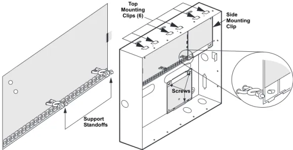
To mount the panel (see Figure 2):
1. Remove the panel door and remove the necessary wiring knockouts. Be careful not to dam-age the circuit board.
2. Feed all wires through wiring knockouts and place the panel in position against the wall. 3. Level the panel and mark the top and bottom mounting holes.
4. Install anchors where studs are not present.
5. Partially insert screws into the two top mounting hole locations, then hang the panel on the two screws.
Speaker Siren (60-528 or 13-060) 18 ga.—100 ft. 0 mA 500 mA
*Maximum current draw for the SnapCards does not include the load which may be applied to their auxiliary DC supply.
Table 1: Maximum Device Wire Length and MIn./Max. Current Draw (Continued)
Device Max. Wire Length to Panel Standby mA Draw Alarm mA Draw
Table 2: Total System Wire Length Allowed
Wire Type Total System Wire
18-gauge, unshielded
18-gauge, shielded 4,000 ft.3,000 ft.
22-gauge, unshielded
22-gauge, shielded 4,000 ft.3,000 ft.
Table 3: Wire Requirements
Device Wire Requirements
AC Power Transformer 2-conductor, 18-gauge, 25 feet max
Earth Ground Single conductor, 16-gauge solid, 25 feet max
Telephone (RJ-31X) 4-conductor
Detection Devices
2- or 4-conductor, 22-gauge, 1,000 feet max 2- or 4-conductor, 18-gauge, 2,500 feet max (based on 30 ohms max loop resistance includ-ing device)
Speakers 2-conductor, 18-gauge, 100 feet max
SuperBus 2000 Devices 4-conductor, 22- or 18-gauge (see Table 1)
Interrogator 200 AVM Power and Microphone 4-conductor, 22-gauge, shielded (see Table 1) 2-Wire Smoke Detectors
2-conductor, 22-gauge, 330 feet max 2-conductor, 18-gauge, 830 feet max
(based on 10-ohms max loop resistance plus a 2k-ohm, end-of-line resistor)
6. Recheck for level, insert the two lower screws, and tighten all four mounting screws.
Figure 2. Mounting the Panel
Identify Panel
Components
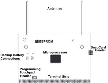
Before installing devices and making wiring connections, familiarize yourself with the main panel components. Figure 3 shows the main component locations.Figure 3. Circuit Board Main Components
Installing Antenna Shrouds
NoteSkip this step for Concord 4 Hybrid and Concord 4 com-mercial systems.
Install a plastic antenna shroud (included with panel) over each antenna and snap them into the holes on top of the enclosure (see Figure 4).
Figure 4. Installing Antenna Shrouds
+
_
Mounting
Holes MountingHoles
+ _ B LK RED Programming Touchpad Header Antennas Microprocessor Terminal Strip EEPROM SnapCard Header Backup Battery Connections
Note
For best results, it is recom-mended that you crimp a spade lug on the wire end at the panel and secure the lug to the enclosure as shown in Figure 5.
Connecting the Panel to Earth Ground
For maximum protection from lightning strikes and transients, connect the enclosure to earth ground as shown in Figure 5. Use 16-gauge, solid copper wire from an earth grounded cold water pipe clamp to the enclosure.
Figure 5. Connecting the Panel to Earth Ground
Installing Optional SnapCards
The SnapCard Header on the right side of the panel allows for the installation of one SnapCard. Install the desired SnapCard onto the panel SnapCard Header and secure it in place with two screws, included with the card (see Figure 6).
Connect all necessary input/output wiring using the Installation Instructions included with the card.
Figure 6. Installing a SnapCard Note
The panel comes with fac-tory programmed onboard hardwire zones. Install 2k-ohm, end of line (EOL) resistors on all unused fac-tory programmed onboard hardwire zones. If you don’t want to install EOL resistors, delete any unused zones from memory. See Table 7 for onboard hardwire zone factory programming.
Connecting Detection Devices to Panel Zone Inputs
Zone inputs 1 through 8 are supervised using included 2k-ohm, end-of-line resistors at the last device on each circuit. All eight zones accept either normally open (N/O) or normally closed (N/ C) detection devices.
Connecting Intrusion Detection Devices
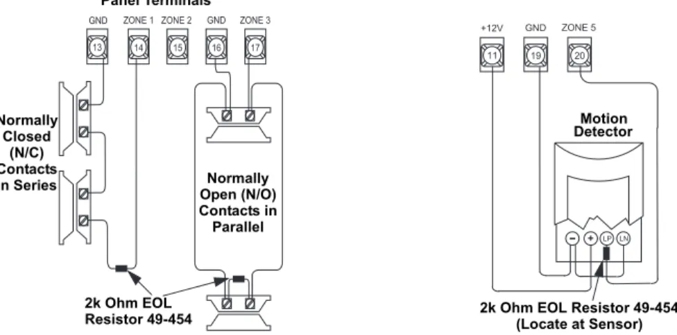
Figure 7 shows the typical wiring for N/C and N/O door/window intrusion detection and the typ-ical wiring for a Detection Systems model DS922 (part no. 13-082) motion detector. The mini-mum available panel voltage for hardwired PIR motion detectors is 8.5 VDC (9.5 VDC for UL listed installations).
Note
When using 2-wire smoke detectors on zone 8, the Two-Wire Smoke setting (in program mode) must be turned on before entering the LEARNSENSORS menu. See ONBOARDOPTIONS—INPUTS in the section “Programming the Panel” for complete details.
+ _ To Water Pipe Pipe Ground Clamp + _ Screw Locations SnapCard Header Connector SnapCard
Figure 7. Connecting N/C and N/O Intrusion Detection and Motion Detector Circuits to the Panel
Connecting 2-Wire Smoke Detectors
Zone input 8 can be set up (in program mode) to accept the following 12 VDC, 2-wire smoke detectors:
• System Sensor models 2400, 2400TH
• ESL models 429AT, 521B, 521BXT—(models 521B and 521BXT require the following dip
switch settings: 1-on, 2-off)
When set up for 2-wire smoke detectors, zone 8 can handle up to 20 smoke detectors (all of the same model, as listed above) with 120 uA maximum idle current per detector. Maximum total loop current allowed in an alarm condition is 90 mA. Connect one or more, 2-wire smoke detec-tors to the panel as shown in Figure 8.
Note
The Two-Wire Smoke set-ting (in program mode) must be on when using 4-wire smoke detectors as shown in Figure 8. See ONBOARD
OPTIONS—INPUTS in the
sec-tion “Programming the Panel” for complete details.
Figure 8. Connecting 2 and 4-Wire Smoke Detectors to the Panel Panel Terminals 2k Ohm EOL Resistor 49-454 1 3 1 4 1 5 1 6 1 7 G N D Z O N E 1 Z O N E 2 G N D Z O N E 3 2k Ohm EOL Resistor 49-454 Normally Closed (N/C) Contacts In Series Normally Open (N/O) Contacts in Parallel L P - + L N 1 9 2 0 G N D Z O N E 5 1 1 + 1 2 V Motion Detector
2k Ohm EOL Resistor 49-454 (Locate at Sensor)
Use only the 2-wire smoke detector models described above. Alarm signals from other detectors may not be processed correctly if the panel has lost AC power and is operating only from the backup battery.
Caution
!
2k Ohm EOL (Locate at Last Detector)Resistor 49-454
2-Wire 4-Wire 2 2 G N D 2 3 2 4 Z O N E 7 2 W S M KZ O N E 8 + C O M . . . .+ -C O M NO NO + C O M . . . .+ -C O M NO NO 2 2 G N D 2 3 2 4 Z O N E 7 2 W S M KZ O N E 8 + -+ -Model 449AT 2k Ohm EOL (Locate at Last Detector)Resistor 49-454
Connecting 4-Wire Smoke Detectors
Zone input 8 can be used with 4-wire smoke detectors that latch and remain in the alarm state until power is removed, then restored to the detector. The panel provides this power interruption from terminal 24 (2W SMK ZONE 8) only when zone 8 is learned into sensor group 26 (fire) and the Two-Wire Smoke option is on.
Note
Zone 8 must be learned into sensor group 26 (fire) and the 2-Wire Smoke feature must be on for connected smoke detectors to reset after canceling a fire alarm.
Table 4 describes the minimum available panel power. Use only 4-wire smoke detectors that operate at these power limits. Connect up to five Sentrol (ESL) model 449AT (part no. 13-360) smoke detectors to panel power and zone 8 input as shown in Figure 8.
Connecting Speakers
NoteInstall all sirens/speakers indoors, in a concealed loca-tion.
The panel provides one siren driver output for intrusion (steady), fire (temporal 3), and auxiliary (on-off-on-off) alarm sounds. This output trips only for partition 1 alarms.
The output can drive a single 8-ohm speaker or multiple speaker circuit of 8-ohms or higher (as shown in the following speaker wiring diagrams). Compatible speakers are described below.
Note
Do not connect a bell or piezo siren to the speaker output (terminals 7 and 8).
15-Watt Speaker (13-060)
For exterior siren applications, connect the speaker to the panel using 18-gauge wire as shown in Figure 9.
Figure 9. Connecting Exterior Speakers to the Panel
Table 4: Panel Minimum Available Power Min. Voltage/Max. Current Available 8.3 VDC, up to 30 mA total (combined alarm) current 8.1 VDC, up to 40 mA total (combined alarm) current 7.6 VDC, up to 60 mA total (combined alarm) current 7.1 VDC, up to 80 mA total (combined alarm) current
Caution
!
To avoid disabling the panel speaker output, do not make speaker connections with the panel powered up.
Splice
Speaker Speaker
2 8-Ohm Speakers in Series (16 Ohms)
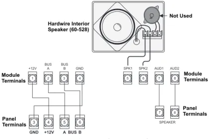
Hardwire Interior Speaker (60-528)
Connect interior speakers to the panel using 18-gauge wire as shown in Figure 10.
Figure 10. Connecting Hardwire Interior Speakers
Connecting Exterior/Interior Piezo Sirens
Output 1
Note
For 24-hour backup, exter-nal power drain is limited to 90 mA (during normal standy condition), using a 4.5 Ah battery, or 190 mA continuous using a 7.0 Ah battery.
Onboard output 1 (OUT 1—terminal 9) is a 9 to 14 VDC switched, programmable output that can handle a maximum of 1,000 mA current. The default setting (01614) activates the output 30 seconds after a police or fire alarm condition occurs. This allows you to connect a piezo siren without changing the output configuration number in programming. This output is typically used for exterior siren applications. (For more information on output configuration numbers, see “Onboard Options Menu”.)
Piezo Dynamic Exterior Siren (13-950) Note
This siren is not UL approved for use as an outdoor sounding device. Connect the siren to panel as shown in Figure 11.
Figure 11. Connecting Exterior Sirens
Connect only the large speaker to the panel terminals 7 and 8 as shown. The smaller speaker cannot handle to output of terminals 7 and 8. To avoid damaging the speaker, the smaller speaker should not be connected to terminals 7 and 8.
Caution
!
8 7 Speaker Not Used Panel Terminals Not Used Not Used Speaker Panel Terminals 7 8 9 O U T 1 1 3 G N D Red Panel Terminals BlackOutput 2
Onboard output 2 (OUT 2—terminal 10) is an open-collector (switched path-to-ground), pro-grammable output that can handle a maximum of 300 mA current sink and up to 14 VDC. The default setting (01710) activates the output for status and alarm tones, allowing for a piezo siren connection without changing the output configuration number. This output is typically used for interior siren applications. (For more information on output configuration numbers, see “Onboard Options Menu”.)
Hardwire Interior Siren (13-949)
This siren has two inputs; steady (#1) and warble (#2). Use the steady (#1) terminal for Concord 4 panels. The siren also includes a cover tamper switch that can be connected to a hardwire zone input on the panel, SnapCard or SuperBus 2000 Hardwire Input Module. Connect the siren to the panel/zone input terminals as shown in Figure 12.
Figure 12. Connecting Exterior and Interior Sirens
Connecting an Interrogator 200 Audio Verification Module (60-677)
Connect the Interrogator 200 Audio Verification Module (AVM) to the panel terminals as shown in Figure 13. Partition 1 use only.Figure 13. Connecting an Interrogator 200 AVM
S W S W G N D # 1 # 2 1 0 O U T 2 1 1 + 1 2 V Panel 2k Ohm Resistor 49-454 Terminals To Zone Input
If a speaker is already connected to panel terminals 7 and 8, the Interrogator 200 speaker must be hooked up in series with that speaker to provide a 16-ohm load. Hook-ing up speakers in parallel to panel terminals 7 and 8 creates a 4-ohm load that can cause permanent damage to the panel.
Caution
!
7 8 S P E A K E R 1 3 1 1 G N D + 1 2 V 1 2 M I C Panel Terminals Yellow Splice Cable Shield Speaker Microphone Cable CableConnecting SuperBus 2000 Touchpads
SuperBus 2000 touchpads may have wires or screw terminals. All use the same wiring scheme for power and bus connections. Connect touchpads to the as shown in Figure 14.
Figure 14. Connecting Touchpads to the Panel
Installing SuperBus 2000 Modules
SuperBus 2000 modules can be installed inside the panel cabinet or away from the panel with their included enclosure.
Mounting Modules Inside the Panel Enclosure
Use the following guidelines when mounting modules inside the panel enclosure (see Figure 15): • Up to 4 of the SuperBus 2000 modules listed in Table 1 can be mounted inside the cabinet. • The 2 Amp Power Supply and Phone Interface/Voice Module each use two mounting spaces
when mounted inside the panel enclosure.
• The panel includes two support standoffs you install to secure module backplates to the panel.
Note
Even if you don’t plan to mount modules inside the cabinet, install the support standoffs for future use and to avoid losing them.
• Install the standoffs at the locations shown.
• The cabinet has built-in mounting clips on the top and sides that module backplates slide onto for mounting.
Figure 15. Installing SuperBus 2000 Modules
3 4 5 6 + 1 2 V A B U S B G N D 3 4 5 6 + 1 2 V A B G N D B U S + 1 2 V A B G N D / C O M Touchpads +1 2V — R ed B u s A— Gr ee n Bus B— Whit e or Y el low G ND— Black Panel Terminals with Wires Touchpads with Terminals Support Standoffs Top Mounting Clips (6) Side Mounting Clip Screws
SuperBus 2000 2 Amp Power Supply (600-1019)
Refer to power supply installation instructions for the mounting procedure. Note
Do not connect power (AC and battery) to the power supply until the panel is ready for power up. For power supply AC and bat-tery connections, see the SuperBus 2000 2 Amp Power Supply Installation Instructions.
Connect the power supply to the panel terminals and devices to be powered as shown in Figure 16.
Figure 16. Wiring the SuperBus 2 Amp Power Supply to the Panel
SuperBus 2000 Transceiver Module (600-1025-01-95R) and SuperBus 2000
RF Receiver Module (60-764-95R-01)
Note
When installing SuperBus 2000 RF Receiver Modules, the Antenna Tamper feature must be set to off (see REPORTING—GLOBAL in the “Programming” section).
The transceiver and receiver expand RF reception range when placed in the vicinity of sensors on the fringe of panel RF reception.
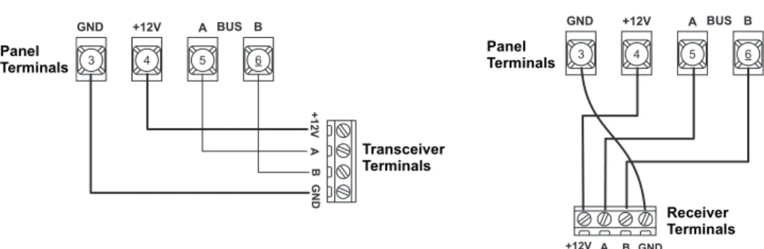
Refer to trasceiver or receiver installation instructions for the mounting procedure. Connect the transceiver and receiver (up to four total) to the panel as shown in Figure 17.
Figure 17. Wiring the SuperBus 2000 RF Transceiver and RF Receiver to the Panel
SuperBus 2000 Voice Only Module
The module can be mounted inside or outside of the control panel cabinet. Refer to the SuperBus
2000 Voice Only Module Installation Instructions included with each module, for complete
mounting instructions. 2 4 V A C 2 4 V A C + 1 2 V B U S A B U S B G N D + 1 2 V O U T G N D Z O N E G N D 3 4 5 6 + 1 2 V A B G N D B U S NO C ON NE CT IO N Panel Terminals Power Supply Terminals To power inputs on devices 3 4 5 6 + 1 2 V A B G N D B U S +1 2V A B G N D Panel Terminals Transceiver Terminals 3 4 5 6 + 1 2 V A B G N D B U S + 1 2 V A B G N D Receiver Terminals Panel Terminals
Note
In UL Listed installations, the Voice Only Module is for supplementary use only.
The module requires panel power and bus connections, and speaker connection through panel terminals as shown in Figure 18.
Figure 18. Wiring for the Voice Only Module Note
For RJ-31X connections, see “Installing an RJ-31X Phone Jack (13-081).
SuperBus 2000 Phone Interface/Voice Module (60-777-01)
The Phone Interface/Voice Module includes two backplates for mounting the module inside the control panel cabinet. The module can also be mounted outside of the control panel using an optional plastic housing (part no. 60-800). Refer to the SuperBus 2000 Phone Interface/Voice
Module Installation Instructions included with each module, for complete mounting instructions.
Note
In UL Listed installations, the Phone Interface/Voice Mod-ule is for supplementary use only.
The module requires panel power and bus connections, phone line connection through panel ter-minals and DB-8 cord (from an RJ-31X jack), and speaker connection through panel terter-minals. Connect the module to the panel power and bus terminals as shown in Figure 19.
For partition 1, connect the phone line to the module through the panel terminals and DB-8 cord (from an RJ-31X jack) as shown in Figure 19. For partitions 2-6 phone connections, see the SuperBus 2000 Phone Interface/Voice Module Installation Instructions.
Figure 19. Wiring for the Phone Interface/Voice Module Note
To prevent status voice mes-sages from being broadcast outside, do not connect exterior speakers to Phone Interface/Voice module ter-minals 6 and 7.
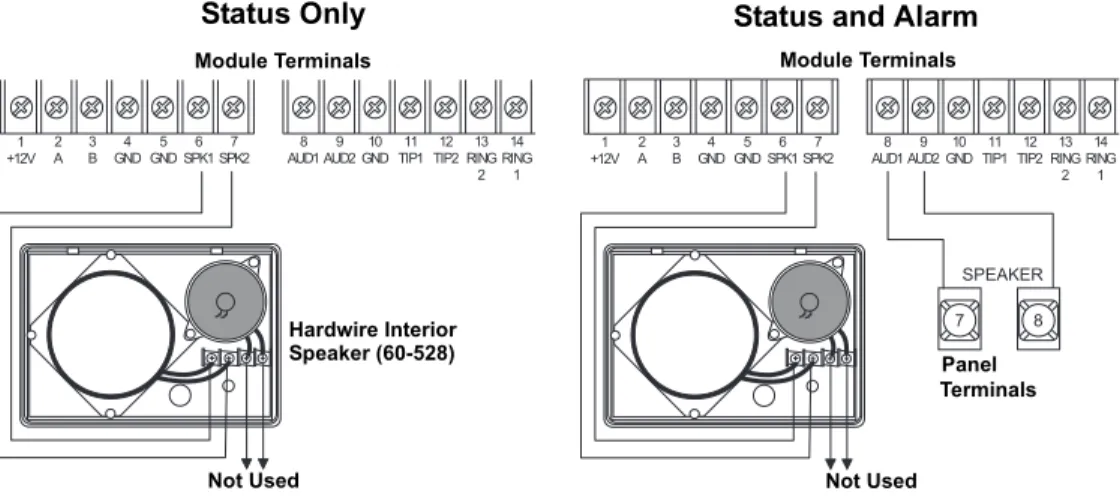
Wiring for Status Voice Messages Only
Connect an interior speaker to the Phone Interface/Voice Module terminals as shown under “Sta-tus” in Figure 20. When connected as shown, the speaker only produces status voice messages. In an alarm, the speaker announces voice status messages.
1 2 3 4 5 6 7 8 + 1 2 V B U SA B U SB G N D S P K 1 S P K 2 A U D 1 A U D 2 4 5 6 A B 3 G N D + 1 2 V B U S 7 8 S P E A K E R Module Terminals Module Terminals Panel Terminals Panel Terminals Hardwire Interior Speaker (60-528) Not Used 1 + 1 2 V 2A B3 G N D4 G N D5 S P K 16 S P K 27 A U D 18 A U D 29 G N D1 0 T I P 11 1 T I P 21 2 R I N G1 3 2 1 4 R I N G 1 2 5 G R N 2 6 2 7 2 8 B R N G R Y R E D Module Terminals Panel Terminals RJ-31X Jack Grn Red Brn Gry DB-8 Cord Gr ee n Re d Br ow n Gr ay 3 4 5 6 + 1 2 V A B U S B G N D 1 + 1 2 V A2 3B G N D4 G N D5 S P K 16 S P K 27 A U D 18 A U D 29 G N D1 0 T I P 11 1 T I P 21 2 R I N G1 3 2 1 4 R I N G 1 Panel Terminals Module Terminals
Wiring for Status and Alarm Messages
Make the connection shown under “Status and Alarm” in Figure 20 only if the Phone Interface/ Voice Module is being installed in Partition 1 and alarm sounds are desired. In an alarm, the speaker alternates between alarm siren tones and voice status messages.
Figure 20. Wiring the Phone Interface/Voice Module for Status Only or Status and Alarm Messages
SuperBus 2000 Energy Saver Module (60-620-01)
Connect the Energy Saver Module to the panel and premises thermostat as shown in Figure 21.
Figure 21. Wiring the Energy Saver Module to the Panel
SuperBus 2000 8Z Input Module (60-774)
Connect the SuperBus 2000 8Z Input Module to the panel as shown in Figure 22.
Connect all necessary input wiring using the Installation Instructions included with the module.
SuperBus 2000 4-Relay Output Module (60-770)
Connect the SuperBus 2000 4-Relay Output Module to the panel as shown in Figure 22.
1 + 1 2 V 2A 3B G N D4 G N D5 S P K 16 S P K 27 A U D 18 A U D 29 G N D1 0 T I P 11 1 T I P 21 2 R I N G1 3 2 1 4 R I N G 1 7 8 S P E A K E R 1 + 1 2 V 2A 3B G N D4 G N D5 S P K 16 S P K 27 A U D 18 A U D 29 G N D1 0 T I P 11 1 T I P 21 2 R I N G1 3 2 1 4 R I N G 1 Module Terminals Hardwire Interior Speaker (60-528)
Not Used Not Used
Module Terminals
Panel Terminals
Status Only Status and Alarm
1 2 3 4 5 6 H E A T O F F A / C 5 0 6 0 7 0 8 0 9 0 3 4 5 6 + 1 2 V A B U S B G N D Panel Terminals
Thermostat Energy Saver Module
Connect all necessary output wiring using the Installation Instructions included with the module.
Figure 22. Wiring Input and Output Modules to the Panel
SuperBus 2000 Cellular Backup Module
Connect the SuperBus 2000 Cellular Backup Module to the SuperBus 2000 2 Amp Power Sup-ply and panel as shown in Figure 23.
Figure 23. Wiring the Cellular Backup Module to the Panel
Input Output 1 2 3 4 5 6 7 8 9 1 0 1 1 1 2 1 3 1 4 1 5 1 6 ZO N E C O M M O N ZO N E 1 ZO N E 2 ZO N E 3 ZO N E 4 ZO N E 5 ZO N E C O M M O N ZO N E C O M M O N ZO N E 6 ZO N E 7 ZO N E C O M M O N ZO N E 8 I D : X X X X X X X X 3 4 5 6 + 1 2 V A B U S B G N D 1 2 3 4 5 6 7 8 9 1 0 1 1 1 2 1 3 1 4 1 5 1 6 1 7 N O 1 N C 1 C O M 1 1 8 ZO N E 1 N O 2 N C 2 C O M 2 N O 3 N C 3 C O M 3 N O 4 N C 4 C O M 4 ZO N E C O M I D : X X X X X X X X 3 4 5 6 + 1 2 V A B U S B G N D Caution
!
Since the SuperBus 2000 Cellular Backup Module draws more than 1 amp, it must be powered by the SuperBus 2000 2 Amp Power Supply and not the panel.
1 2 3 4 5 6 ZC O M ZO N E 1 2 4 V A C 2 4 V A C + 1 2 V B U S A B U S B G N D + 1 2 V O U T G N D Z O N E G N D SuperBus 2000 2 Amp Power Supply Terminals
SuperBus 2000 Automation Module (60-783-02)
Connect the SuperBus 2000 Automation Module to the panel as shown in Figure 24.
Figure 24. Connecting the SuperBus to the Panel
SuperBus 2000 Wireless Gateway-Ready Kit (600-1010)
Connect the SuperBus 2000 Wireless Gateway Module to the SuperBus 2000 terminals as shown in Figure 25.
Figure 25. Connecting the Wireless Gateway Module to the Panel Note
The panel cannot be used on a digital or PBX phone line. These systems are designed for digital type devices only, operating any-where from 5 volts DC and up. The panel uses an ana-log modem and does not have a digital converter, adapter, or interface to oper-ate through such systems.
Installing an RJ-31X Phone Jack (13-081)
Use the following guidelines when installing an RJ-31X phone jack for system control by phone and central station monitoring.
• Locate the RJ-31X jack (CA-38A in Canada) no further than five feet from the panel. • The panel must be connected to a standard analog (loop-start) phone line, that provides 48
volts DC (on-hook or idle).
• For full line seizure, install an RJ-31X phone jack on the premises phone line so the panel is ahead of all phones and other devices on the line. This allows the panel to take control of the phone line when an alarm occurs, even if the phone is in use or off-hook.
Note
Connecting the panel to an analog line off the phone switch places the panel ahead of the phone system, preventing panel access from phones on the pre-mises. However, the panel can still be accessed from off-site phones.
• If an analog line is not available, contact a telecommunications specialist and request an ana-log line off the phone switch (PBX mainframe) or a 1FB (standard business line).
To connect a phone line to the panel using an RJ-31X/CA-38A jack:
1. Run a 4-conductor cable from the TELCO protector block to the jack location (see A in Fig-ure 26).
2. Connect one end of the cable to the jack (see B in Figure 26).
3. At the TELCO protector block, remove the premises phone lines from the block and splice them to the black and white (or yellow) wires of the 4-conductor cable (see C in Figure 26).
1 2 3 4 5 6 ZC O M ZO N E 1 3 4 5 6 + 1 2 V A B U S B G N D Panel Terminals Automation Device
Automation Module Circuit Board DB-9 Serial Cable
Caution
!
Since the SuperBus Wireless Gateway-Ready Kit draws more than 1 amp, it must be powered by the SuperBus 2000 2 Amp Power Supply and not the panel.
+ 1 2 V A B G N D Z 1 Z C O M 2 4 V A C 2 4 V A C + 1 2 V B U S A B U S B G N D + 1 2 V O U T G N D Z O N E G N D SuperBus 2000 2 Amp Power Supply Terminals
4. Connect the green and red wires from the 4-conductor cable to the TIP (+) and RING (-) posts on the block (see D in Figure 26).
5. Check the phones on the premises for dial tone and the ability to dial out and make phone calls. If phones do not work correctly, check all wiring and correct where necessary. Proceed to the “Troubleshooting” section of this manual if problems persist.
Connecting the Phone Line to the Panel with a DB-8 Cord
After installing the RJ-31X jack, you are ready to connect the phone line to the panel. A DB-8 cord (not included) uses a plug at one end for connecting to the RJ-31X module and flying leads on the other end for panel terminal connections.
To connect the DB-8 cord to the panel terminals and RJ-31X jack (see Figure 26):
1. Connect the green, brown, gray, and red flying leads from the DB-8 cord to panel terminals 25, 26, 27, and 28.
2. Insert the DB-8 cord’s plug into the RJ-31X.
3. Check the phones on the premises for dial tone and the ability to dial out and make phone calls. If phones do not work correctly, check all wiring and correct where necessary. Proceed to the “Troubleshooting” section of this manual if problems persist.
Figure 26. Wiring an RJ-31X Jack and DB-8 Cord to the Panel
Connecting the AC Power Transformer
The panel must be powered by a plug-in stepdown transformer that supplies 16.5 VAC, 40 VA (600-1023 or 600-1023-CN).
For systems that include X10 Lamp Modules, the panel must be powered with the Line Carrier Power Transformer that supplies 16.5 VAC, 40 VA (600-1024 or 600-1024-CN). Connect the power transformer to the panel as shown in Figure 27.
Brn Gry RJ-31X Jack Red Grn TELCO Protector Block Green Red
Lines from Phones on Premises Dealer Cable Run TIP (+) RING(-) Bl ack Whi te (or Y e llow ) Re d Gr een
Black White(or Yellow)
Green Red 2 5 G R N 2 6 2 7 2 8 B R N G R Y R E D T E L C O H O U S E Brn Gry Grn Red DB-8 Cord RJ-31X Jack Gr ee n Br ow n Gr ay Re d A B C D
Do not plug in the power transformer or connect the backup battery at this time. The panel must be powered up using the sequence of steps described in the next section, “Powering Up the Panel.”
Figure 27. Connecting Panel Power Transformer and Backup Battery
Powering Up the Panel
After connecting and wiring all devices to the panel, you are ready to apply AC and backup bat-tery power to the panel.
To power up the panel (see Figure 27):
1. Connect the red and black battery leads (included with panel) to the lugs on the panel. 2. Connect the other ends of the battery leads to the battery terminals.
3. Plug the transformer into an outlet that is not controlled by a switch.
Alphanumeric touchpads display ************, then SCANNING BUS DEVICES, and finally a date and time display.
Note
If alphanumeric touchpads don’t display anything, immediately unplug the transformer and disconnect the backup battery. Refer to the “Troubleshooting” sec-tion.
4. To permanently mount the transformer, unplug it and remove the existing screw securing the AC outlet cover.
Hold the outlet cover in place and plug the transformer into the lower receptacle. 5. Use the screw supplied with the transformer to secure the transformer to the outlet cover.
Programming
the Panel
For on-site system programming, an alphanumeric touchpad is required.Entering Program Mode
Entering program mode is done using an installer/dealer code (default = 4321). The system can be put into program mode only when all partitions are disarmed.
Note
If the system is powered up after the programming touchpad is connected or if a bus command scan is exe-cuted, the programming touchpad will be “learned” into the system and must later be manually deleted.
To enter program mode:
1. Make sure the system is disarmed in all partitions.
2. Press 8 + 4321 + 0 + 0. The display shows SYSTEM PROGRAMMING.
To enter programming mode using a programming touchpad:
1. Connect the red, black, green, and white wires from the Programming Touchpad Cable (60-791) to the power and bus wires/terminals on an alphanumeric touchpad, matching the +12V (red), Bus A (green), Bus B (white), and GND (black) on each.
2. Make sure the system is powered up and disarmed.
3. Connect the plug on the cable onto the panel programming touchpad header (see Figure 28). 4. Press 8 + 4321 + 0 + 2. The touchpad sounds one short beep. Press * and verify that the
dis-play shows SERVICE TOUCHPAD ACTIVE.
5. Press 8 + 4321 + 0 + 0 and the display shows SYSTEM PROGRAMMING.
+
_
Panel
Backup Battery Connections
Battery Red Black 1 2 1 6 . 5 V A C Terminals
Use extreme caution when securing the transformer to a metal outlet cover. You could receive a serious shock if a metal outlet cover drops down onto the prongs of the plug while you are securing the transformer and cover to the outlet box.
6. After programming is completed, simply disconnect the touchpad from the panel header.
Figure 28. Connecting a Programming Touchpad
Touchpad Button Programming Functions
In program mode, touchpad buttons let you navigate to all installer programming menus for con-figuring the system. Table 5 describes the touchpad button functions in program mode.
Moving Through Program Mode Tiers and Menus
There are two basic tiers of programming menus (see Figure 29). Tier 1 Menus Tier 2 MenusFigure 29. Tier 1 and Tier 2 Program Menus
Table 5: Touchpad Button Functions
Button Programming Function
# Selects menu item or data entry.
* Deselects menu item or data entry (if pressed before #).
A ( )
B ( ) Scroll through available options at the current menu tier. Also scroll through sen-sor text options during sensor text programming.
C Enters pauses when programming phone numbers.
D Deletes certain programmed settings.
0 thru 9 Enter numeric values wherever needed.
1 & 2 Select off (1) or on (2) wherever needed.
1 thru 6 Press and hold to enter alphabetical characters A thru F for account numbers.
7 & 9 Press and hold to enter * (7) or # (9) for phone numbers.
SYSTEM PRO-GRAMMING # · SECURITY B A PHONES B A PHONE OPTIONS B A TIMERS B A B A # · # · # · # · B A LIGHT CONTROL B A TOUCHPAD OPTIONS B A REPORTING B A SIREN OPTIONS B A # · # · # · # · B A SENSORS B A AUDIO VERIFICATION B A ACCESSORY MODULES B A ONBOARD OPTIONS B A # · # · # · # · B A MACRO KEYS 6 0 7 3 4 G 3 0 8 D . D S F S t a t u s F e a t u r e s p r e s s b o t h L i g h t s S y s t e m A w a y P a g e r O f f N o D e l a y p r e s s b o t h p r e s s b o t h T e s t S y s t e m W e e k l y S i l e n t S t a y D * 7 0 # 8 B A 4 1 5 6 2 3 B y p a s s M e n u C 9 Programming Touchpad Cable (60-791)