35
FUEL SAVING STRATEGY IN SPARK IGNITION ENGINE
USING FUZZY LOGIC ENGINE TORQUE CONTROL
Aris Triwiyatno
*)and Sumardi
Department of Electrical Engineering, Diponegoro University, Control System Engineering Lab., Department of Electrical Engineering, Diponegoro University, Tembalang, Semarang 50275, Indonesia
*)
E-mail: [email protected]
Abstract
In the case of injection gasoline engine, or better known as spark ignition engines, an effort to improve engine performance as well as to reduce fuel consumption is a fairly complex problem. Generally, engine performance improvement efforts will lead to increase in fuel consumption. However, this problem can be solved by implementing engine torque control based on intelligent regulation such as the fuzzy logic inference system. In this study, fuzzy logic engine torque regulation is used to control the throttle position entered by the driver to achieve optimal engine torque. An engine torque vs. throttle position and engine speed mapping for vehicles with economical function is used to build this control process regulation. From the simulation result, it can be concluded that this control strategy is very effective to reduce fuel consumption and simultaneously to optimize the engine performance.
Abstrak
Strategi Penghematan Bahan Bakar pada Mesin dengan Pemicu Busi Melalui Kontrol Torsi Mesin dengan Logika Fuzzy. Pada kasus kontrol mesin bensin, atau lebih dikenal sebagai mesin pengapian busi, upaya untuk meningkatkan kinerja mesin sekaligus mengurangi konsumsi bahan bakar adalah masalah yang cukup kompleks. Umumnya, upaya peningkatan performa mesin akan menyebabkan peningkatan konsumsi bahan bakar. Namun, hal ini dapat diselesaikan dengan melakukan kontrol torsi mesin berdasarkan peraturan cerdas seperti sistem inferensi logika
fuzzy. Dalam studi ini, regulasi torsi mesin dengan logika fuzzy digunakan untuk mengontrol posisi throttle yang dimasukkan oleh pengemudi untuk mencapai torsi mesin yang optimal. Pemetaan torsi mesin vs posisi throttle dan kecepatan putar mesin untuk kendaraan dengan tujuan ekonomis digunakan untuk mendesain aturan proses kontrol. Dari hasil simulasi dapat disimpulkan bahwa strategi kontrol dengan logika fuzzy sangat efektif untuk mengurangi konsumsi bahan bakar dan sekaligus mengoptimalkan kinerja mesin.
Keywords: engine torque control, fuzzy logic, spark ignition engine
1. Introduction
Over the last three decades, there has been a dramatic evolution in spark ignition engine control systems, largely driven by government regulations and policies aimed at improving fuel economy and reducing emissions [1–5]. It is increasingly important to achieve control over transient behavior and to meet performance objectives over the life of the vehicle. This requires the development of high performance and robust power train controllers. The performance objectives are often conflicting, or at least interrelated. Due to these reasons, automotive engines control is needed.
Control of automotive engines focuses on a various issues, including control of idle speed, spark timing, air-
This paper focuses in particular on improving fuel economy using engine torque control. The goal is to develop algorithms which can control engine torque effectively, thus providing adequate fuel control under many operations of engine using engine torque mapping database input control. One way to potentially meet these performance requirements is by introducing a novel method of controlling engine torque based on engine torque management strategy (torque reference selection using engine torque vs. throttle position and engine speed mapping for Economical Vehicle data base) using fuzzy logic control. Takagi-Sugeno’s fuzzy inference system was chosen to provide a soft-shift scheduling of control gain appropriate to different engine operations. By using this method, the throttle opening commanded by the driver will be corrected by throttle correction signal that guarantees engine torque output to follow the desired engine torque input, and simultaneously reduce fuel consumption. In this case, spark ignition engine with automatic transmission model is used to meet a good performance under this controller design.
2. Methods
Spark Ignition Engine Modeling. In this research, we use spark ignition engine model as described in [15]. The model is Ford SI-engine model. The rate of air into the intake manifold can be expressed as the product of two functions; i.e. an empirical function of the throttle plate angle and a function of the atmospheric and manifold pressures, as shown in Equation 1.
ai
m& = f1(θ)f2(Pm) (1)
where \
ai
m& = mass flow rate into manifold (g/s), with
) (
1θ
f = 2 3
00063 . 0 10299 . 0 05231 . 0 821 .
2 − θ+ θ − θ
θ = throttle angle (deg)
) (
2 Pm
f =
⎪ ⎪ ⎪ ⎪ ⎩ ⎪⎪ ⎪ ⎪ ⎨ ⎧ ≥ − ≤ ≤ − − ≤ ≤ − ≤ amb m amb m amb m amb m m amb m amb m amb m amb amb m P P P P P P P P P P P P P P P P P P 2 2 , 1 2 , 2 2 , 2 2 , 1 2 2 m
P = manifold pressure (bar)
amb
P = ambient (atmospheric) pressure (bar), 1 bar
The intake manifold can be modeled as a differential equation for the manifold pressure, as shown in Equation 2.
m
P& =
(
ai ao)
m m m V RT & & −
= 0.41328
(
m&ai−m&ao)
(2)where
R = specific gas constant
T = temperature (K)
Vm = manifold volume (m3)
ao
m& = mass flow rate of air out of the manifold (g/s)
m
P& = rate of change of manifold pressure (bar/s), with P0 = 0.543 bar
The mass flow rate of air that the model pumps into the cylinders from the manifold is described in Equation 3 by an empirically derived equation.
ao
m& = −0.366+0.08979NPm
NPm2 N2Pm0001 . 0 0337 . 0 +
− (3)
where
ao
m& = mass flow rate of air out of the manifold (g/s)
N = engine speed (rad/s)
Pm = manifold pressure (bar)
The torque developed by the engine is described as in Equation 4.
e
T = −181.3+379.36ma+21.91(A/F)
2 2 0028 . 0 26 . 0 ) / ( 85 .0 + σ − σ
− A F
+0.027N−0.000107N2+0.00048Nσ
ma 2ma05 . 0 55 .
2 σ − σ
+
(4)
where
a
m = mass of air in cylinder for combustion (g)
F
A/ = air to fuel ratio
σ = spark advance (degrees before top-dead-
center/TDC)
e
T = torque produced by the engine (Nm)
Fuel consumption can be estimated with air-to-fuel ratio estimation (A/F) and mass of air in cylinder for combustion (ma ≈ mao) in Equation 3; as shown in
Equation 5.
Fuel =
F A
ma
/ (5)
where
Fuel = fuel consumption (g)
a
m = mass of air in cylinder for combustion (g)
F
The engine torque less the impeller torque results in engine acceleration; as in Equation 6.
N
Iei & = Te−TL (6)
where
ei
I = engine rotational + impeller moment of
inertia (kg-m2) = 0.14 kg-m2
N& = engine acceleration (rad/s2), with initial engine speed N0= 209.48 rad/s
e
T = torque produced by the engine (Nm)
L
T = load torque (Nm)
Load torque (TL) is generally produced by vehicle
dynamics. The vehicle model with 4-step automatic gear transmission that is used in this engine model application is derived based on state-flow model as in [15].
Engine Torque Management Strategy. Basically, the engine torque management strategy uses throttle opening control function, air to fuel ratio (AFR) and ignition timing simultaneously to produce desired engine torque. In practical reality, the desired engine torque does not exist, because the input given by the driver on the system is the position of the accelerator pedal (pedal position) [14]. For that reason, the engine torque control strategy is known as the mapping between the position of throttle opening (pedal position) and engine speed with engine torque command [12]. Figure 1 shows the mapping for economical vehicle.
In this research, engine torque control regulation conducted only by controlling throttle plate angle. AFR and ignition time is left on the standard setting that ideally yield maximum engine torque, i.e. at 14.7 AFR and the spark advance to 15 degree MBT.
Fuzzy Engine Torque Control. Fuzzy logic controller is one of the controllers based on “if-then” rules that can be used for decision making as in the human mind [16]. At this research, Takagi-Sugeno’s fuzzy inference system (TS FIS) [17] with the input engine torque error and derivative error and output weighting to absolute gain control is used to determine the correction to the throttle plate angle given by the driver.
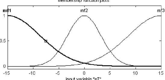
Figure 2, Figure 3, and Figure 4 show membership functions of input and output fuzzy logic controller (TS FIS) to be used, since we need fuzzy inference system as a soft-shift scheduling of control gain appropriate to different engine operations.
Rules of inference mechanism used are as follows: 1. If (eT is mf1) and (deT is mf1) then (eTh is mf1) 2. If (eT is mf1) and (deT is mf2) then (eTh is mf2) 3. If (eT is mf1) and (deT is mf3) then (eTh is mf3) 4. If (eT is mf2) and (deT is mf1) then (eTh is mf3) 5. If (eT is mf2) and (deT is mf2) then (eTh is mf4) 6. If (eT is mf2) and (deT is mf3) then (eTh is mf5) 7. If (eT is mf3) and (deT is mf1) then (eTh is mf4) 8. If (eT is mf3) and (deT is mf2) then (eTh is mf5) 9. If (eT is mf3) and (deT is mf3) then (eTh is mf5)
Following the design above, it can be shown the surface of fuzzy engine torque control input-output in Figure 5.
Figure 2. Membership Functions of Engine Torque Input Error
Figure 3. Membership Functions of Input Derivative Engine Torque Error
Figure 5. The Surface of Input-Output Controller
3. Results and Discussion
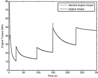
Simulations performed with Matlab Simulink are shown in Figure 6 and Figure 7. We use some input scheme to observe the control process. Some of simulation results without the controller are shown in Figure 8 and Figure 9. Figure 8 shows that there is a significant difference between the actual engine torque and the desired engine torque when the throttle valve opening using the driver is given, as shown in Figure 9. Figure 10 and Figure 11 show the results following the provision of a fuzzy engine torque control based on torque engine mapping for economical vehicle in Figure 1. Figure 10 shows that the engine torque will be closer to the desired engine torque when the throttle valve opening uses the output of the fuzzy gain scheduling control as shown in Figure 11.
Other simulation results, as shown in Table 2, were that the average of integral absolute torque error (IATE, as sum of absolute difference between torque reference as calculated using Figure 1 and torque output of the engine within simulation period) of operation without a controller amounted to 4.722 and by the application of fuzzy engine torque control based on torque engine mapping for economical vehicle is 392.9 or there is an improvement of 1101.83%. The average of fuel consumption of operations without the controller is about 4.248 grams and by the application of fuzzy engine torque control based on torque engine mapping for economical vehicle is about 3,587 or there is a decrement of 19.431%.
Table 2. Statistical Result of Some Scheme Simulations in 300 Seconds
IATE Fuel Consumption (grams) Scheme
uncontrolled controlled fuzzy uncontrolled controlledfuzzy
Scheme 1 3.965 362.2 4.503 3.891
Scheme 2 3.548 321.6 4.377 3.830
Scheme 3 2.320 229.5 3.910 3.684
Scheme 4 9.054 658.3 4.344 2.941
Average 4.722 392.9 4.284 3.587
Improvement 1101.83% 19.431%
Scheme 1: step up throttle degree, no brake Scheme 2: step down throttle degree, no brake Scheme 3: sinusoidal throttle degree, no brake Scheme 4: constant throttle degree, brake in the middle
Figure 7. Fuzzy Controller Sub-System
0 50 100 150 200 250 300
0 10 20 30 40 50 60 70 80
Time (s)
E
n
gi
ne
T
o
rq
ue
(Nm
)
desired engine torque engine torque
Figure 8. Engine Operating without a Controller: Desired Engine Torque vs. Engine Torque
0 50 100 150 200 250 300
0 5 10 15 20 25 30 35 40
Time (s)
T
h
rot
tl
e
O
p
en
in
g
(deg
)
throttle input throttle actual
Figure 9. Engine Operating without a Controller: Throttle Input vs. Throttle Actual
0 50 100 150 200 250 300
0 10 20 30 40 50 60 70 80
Time (s)
E
n
g
ine T
o
rque
(N
m
)
desired engine torque engine torque
Figure 10. Engine Operating with Fuzzy Gain Scheduling: Desired Engine Torque vs. Engine Torque
0 50 100 150 200 250 300
0 5 10 15 20 25 30 35 40
Time (s)
T
h
rot
tl
e
O
p
en
in
g
(deg
)
throttle input throttle actual
4. Conclusion
From the simulation results, some conclusions can be made: i.e. (i) The use of fuzzy engine torque control in a spark ignition engine is very effective to improve engine performance, by improving its ability to track desired engine torque according to the driver's accelerator input data and information on pedal position and engine speed to the desired engine torque for Economical Vehicle mapping. The average of integral absolute torque error of some testing scheme show improvements up to 1101.83%; (ii) The use of fuzzy engine torque control in a spark ignition engine applications is also very effective to reduce fuel consumption by reducing the throttle opening that is excessively supplied by the driver to achieve the corresponding engine torque. The rate of fuel savings of some testing schemes achieved an average of 19.431%; (iii) Further research is required to complete this method since there are still many parameters of engine causing uncertainties in modeling of spark ignition engine. Since the model has many uncertainties and nonlinear system, strong control analysis is needed to solve the problem.
References
[1] P. Yoon, S. Park, M. Sunwoo, Seoul 2000
FISITA World Automotive Congress, Seoul, Korea, 2000, F2000A177, p.1.
[2] R. Ford, K. Glover, Proceeding of AVEC 2000,
5th Int'l Symposium on Advanced Vehicle Control, Ann Arbor, Michigan, 2000, p.89.
[3] D. Khiar, J. Lauber, T. Floquet, G. Colin, T.M. Guerra, Y. Chamaillard, Control Eng. Pract.
Elsevier, 15/12 (2007) 1446.
[4] T. Huang, D. Liu, H. Javaherian, N. Jin,
Proceedings of the 17th World Congress, The International Federation of Automatic Control, Seoul, Korea, 2008, p.9453.
[5] T. Nagata, M. Tomizuka, American Control
Conference, ACC '09, New Jersey, USA, 2009, p.2064.
[6] J. Pfeiffer, J. Hedrick, Nonlinear Algorithms for Simultaneous Speed Tracking and Air-Fuel Ratio Control in an Automobile Engine, SAE Technical Paper 1999-01-0547, 1999, doi:10.4271/1999-01-0547. http://papers.sae.org/1999-01-0547/.
[7] D.J. Stroh, M.A. Franchek, J.M. Kerns,
Proceeding of AVEC 2000, 5th Int'l Symposium on Advanced Vehicle Control, Ann Arbor, Michigan, 2000, p.70.
[8] A. Nugroho, Bachelor Final Project, Department of Electrical Engineering, Faculty of Industrial Technology, ITS, Surabaya, Indonesia, 2004. [9] A. Salim, Master Thesis, Dept. of Electrical
Engineering, Faculty of Industrial Technology, ITS, Surabaya, Indonesia, 2004.
[10] A. Triwiyatno, Master Thesis, Department of Electrical Engineering, Faculty of Industrial Technology, ITS, Surabaya, Indonesia, 2005. [11] Irianto, Master Thesis, Department of Electrical
Engineering, Faculty of Industrial Technology, ITS, Surabaya, Indonesia, 2005.
[12] N. Heintz, M. Mews, G. Stier, A. Beaumont, et
al., An Approach to Torque-Based Engine
Management Systems, SAE Technical Paper 2001-01-0269, 2001, doi:10.4271/2001-01-0269.
http://papers.sae.org/2001-01-0269/.
[13] I. Kolmanovsky, M. Druzhinina, J. Sun,
Proceeding of AVEC 2000, 5th Int'l Symposium on Advanced Vehicle Control, Michigan, 2000, p.1.
[14] D.M. Lamberson, Thesis Master, Mechanical
Engineering, University of California at Berkeley, California, 2003.
[15] The MathWorks Inc., Using Simulink and
Stateflow in Automotive Applications, The MathWorks Inc., USA, 1998, p.92.
[16] M. Braae, D.A. Rutherford, Automatica 15 (1979)
553.
![Figure 1. Mapping Pedal Position and Engine Speed with Engine Torque Command for Economical Vehicle [12]](https://thumb-us.123doks.com/thumbv2/123dok_us/8076660.2139739/3.892.221.668.756.1087/figure-mapping-position-engine-engine-command-economical-vehicle.webp)