161
Flexural Strength Of Prestressed Concrete
Beams With Openings And Strengthened With
CFRP Sheets
Dr. Mustafa B. Dawood, Haider H. A. Al-Katib
Abstract: This paper presents an experimental investigation of flexural strength of pretensioned prestressed concrete beams with openings and strengthened with (CFRP) sheets, tested as simply supported span subjected under two-point loading. The experimental work includes testing of nine prestressed concrete beams specimens with dimensions (effective length 1800mm × depth 300mm × width 130mm), two of which were without openings as a control beams (one without and the other with strengthening by CFRP), three were with openings, and the remaining four with openings and strengthened with CFRP sheets. The opening was made at square shape (100×100) mm in flexure zone at mid span of beam. Several design parameters were varied such as: opening width, opening depth and strengthening of openings of beams by CFRP sheets at compression and tension zone. Experimental results showed that the presence of square opening (with ratio h/H= 0.333) and rectangular opening (with ratio h/H from 0.333-0.5) at mid span of beams decreased the ultimate load about (5.5)% and (5.5-33.1)% respectively when compared with beam without openings (control beam). The externally strengthened prestressed concrete beams with bonded CFRP sheets showed a significant increase at the ultimate load, this increase was about (10.9-28.8)% for flexure beams when compared with the unstrengthened beams. Moreover, the load-deflection curves for flexure beams strengthened with CFRP sheets were stiffer than the unstrengthened beams. Therefore, this results gave a good indication about using CFRP sheets in improvement of deflection.
IndexTerms: Flexural,Pretensioned, PrestressedConcreteBeams,OpeningWidth,OpeningDepth,CFRPSheets,StrengtheningatCompressionand TensionZone.
————————————————————
1
I
NTRODUCTIONPrestressing can be defined in general terms as the preloading of a structure, before application of the service loads, so as to improve its performance in specific ways. Although the principles and techniques of prestressing have been applied to structures of many types and materials, the most common application is in the design of structural concrete. Concrete is essentially a compression materials. Its strength in tension is much lower than that in compression, and in many cases, in design, the tensile resistance is discounted altogether. The prestressing of concrete, therefore, naturally involves application of a compression loading prior to applying the anticipated service loads, so that tensile stresses that otherwise would occur are reduced or eliminated [1]. At construction of new buildings, many ducts and pipes are needed to accommodate basic service such as air-condition, computer network, electricity and water supply. Figure (1) shows a view of the typical layout of service ducts for a high-rise building. Often, these ducts and pipes are placed below the beam and, for architecture purposes are covered by a secondary ceiling, therefore creating additional dead load. The height of additional dead space added to the overall building height depends on the number and depth of ducts to be accommodated. The depth of ducts or pipes may range from a couple of centimeters to as much as half a meter [2].
Figure (1) Typical Layout of Service Ducts and Pipes [2].
An alterative arrangement is to pass the ducts across transverse openings at the beams of floor. As shown in Figure (2), this arrangement of building services leads to significant reduction in the floor height and resulting more economical design. For low height building, the achieved savings may not be important compared to the total cost. While for multi-floor building, any saving in floor multiplying it by the number of floors can give a significant saving in the overall height, air-condition length, partition and wall surfaces and overall dead load on the foundation.
____________________________
Prof. Dr. Mustafa B. Dawood, Lecturer. College of Eng. Univ. of Babylon-Iraq
E-mail: dawoodcivileng@yahoo.com
Ph.D. Student Haider A. A. Al-Katib, Lecturer. College of Eng. Univ. of Kufa-Iraq
Figure (2) Alternative Arrangement of Service Ducts and Pipes[2].
2
C
LASSIFICATION OFO
PENINGSThere is various shapes and sizes of transverse openings in beams. Prentazs (1968) [3], at his experimental work, studied different shapes of opening as shown in Figure (3). Though of possible various shapes of openings, the most practicable opening used in construction is a rectangular and a circular. For service pipes the preferable opening is circular, like electrical supply, plumbing and water supply. On the other hand, the ducts of air-conditioning are usually rectangular shape, and they are accommodated in rectangular openings through beams. Sometimes, the corners of a rectangular opening are rounded off with the intention of reducing possible stress concentration at sharp corners, thereby improving the cracking behavior of the beam in service.
Figure (3) Openings Shapes Considered by Prentazs [3].
With respect to the opening's size, many researchers specified the opening as small and large one without giving a clear range for definition of size. Mansur and Hasant (1979) [4] considered the circular and square opening as small openings. While Somes and Corley (1974) [5], specified the circular opening as large one when the ratio of opening diameter to the total depth of beam exceeds (0.25). However, the authors considered that the fundamental classification of opening as either small or large one depended on the structural behavior of the beam. If the opening is small enough to keep the same behavior of beam, or if the usual beam theory applies, the opening will be classified as small opening. If there is a change in the behavior of beams due to the presence of openings, then the openings may be classified as a large openings.
3
T
YPES OFC
RACKINGA
ROUND OFO
PENINGFive critical locations for potential cracking of prestressed concrete beams with opening in shear span are identified in Figure (4). These are: (a) at the edges of the opening due to prestressed force; (b) at the corners of the opening due to framing action at the opening region; (c) in the chord members due to shear; (d) in the chord members due to flexural stresses that arise from secondary moments; and (e) in the tension chord member due to normal tensile stresses. The shear cracks and tension cracks can trigger the complete collapse of the beam [6].
Figure (4) Types of Cracking Around Opening [6].
The typical crack pattern for T-beams with multi openings at initial cracking, near the service load stage (70% of Mu), and at the ultimate stage (Mu) is shown in Figure (5). The initial cracks are caused by localized stresses Figure (5a) at the openings. The cracking also indicated Vierendeel truss-like end forces on the chords below some of the openings. As the load on the beam increased, the crack pattern changed from localized cracking to a more uniform caused by the flexure of the overall T-beam. At failure, there are flexural cracks across the middle half of the T-beam. In beams, the shear reinforcement adjacents to the openings are not bent into the flange, shear cracks observed to extend from the top corner of the opening to the underside of the flange, which then extends horizontally the flange-web interface [7].
163
4
M
ATERIALS USED TO FABRICATE THE SPECIMENSThe materials used in this investigation are commercially available materials, which include cement, fine aggregates,
coarse aggregates, admixture (Hyperplast PC260),
reinforcing bars and strand are used in designing and casting of pretensioned prestressed concrete beams, while CFRP sheets and epoxy resin are used for strengthening of these beams. The specifications and properties of these materials are as under:
4.1 CEMENT
High sulfate resistant cement manufactured by united cement company commercially known (Karbala) used throughout this study which confirmed to the Iraqi Specification No.5/ 1984 [8].
4.2 COARSE AGGREGATE (GRAVEL)
Natural crushed gravel of maximum size 19mm obtained from Al-Badra-wa-Jasan region was used throughout the experimental work. Its grading satisfied the limits of Iraqi standard No.45/1984 [9] for graded gravel.
4.3 FINE AGGREGATE (SAND)
Natural sand from Karbala region in Iraq was used as fine aggregate. The fine aggregate was sieved at sieve size (4.75mm) to separate the aggregate particle of diameter greater than 4.75mm. The grading test results conform to Iraqi standard No.45/1984 [9].
4.4 ADMIXTURE (HYPERPLAST PC260)
Hyperplast PC260 is a high performance super plasticising admixture based on polycarboxylic ether polymers with long chains specially designed to enable the water content of concrete to perform more effectively. This effect can be used in high strength concrete and flow able concrete mixes, to achieve highest concrete durability and performance. The guidance dosage of Hyperplast PC260 is (0.5 - 3) liter/100kg of cement. One liter/100kg of cement was used in the present study. Hyperplast PC260 complies with ASTM C494 [10], type A and type G, depending on dosage used.
4.5 STEEL REINFORCING BARS
For all beams, two sizes of steel reinforcing deformed bars were used. Bar size Ф12 mm used as longitudinal reinforcement, and bars of size Ф10 mm were used as transverse reinforcement (closed stirrups) which was of Ukrainian origin. Three tension bars of each 12mm and 10mm diameter deformed steel bars were tested to acquire the yield stress and ultimate strength of the reinforcement. The reinforcing bars have been tested in the Quality Control Laboratory of Kufa University and the experiments were
conducted in accordance with ASTM A370-2005
specifications [11] , as shown in Table (1)
Table (1) MaterialProperties of Steel Reinforcement
Bar Size
Area Ab, (mm2)
Yield Stress (MPa)
Tensile Strength
(Mpa)
Weight per 1 Meter
Length (g /m)
Elong.
Ф10mm 78.54 645 723 602 10.1%
Ф12mm 113 650 732 841 14%
4.6 STRAND
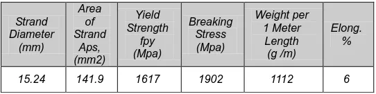
For all beams, one 7-wire steel strand of 15.24 mm diameter (grade 270) was used. Tensile tests were conducted on several specimens. A minimum of three specimens, prepared as samples from the strands which were used in the tested beams accordance with ASTM A416M-2005 [12]. Yield stress and breaking stress are summarized in Table (2). The tensile tests were performed by using the testing machine available at the Material Laboratory of the Material Engineering College at Babylon University.
Table (2) Material Properties for Steel Strand.
Strand Diameter
(mm)
Area of Strand
Aps, (mm2)
Yield Strength
fpy (Mpa)
Breaking Stress (Mpa)
Weight per 1 Meter Length
(g /m)
Elong. %
15.24 141.9 1617 1902 1112 6
4.7 CFRP SHEETS
FRP systems can be used for rehabitating the strength of failed structural members, to strengthen structural members to resist additional loads due to the change in structure uses, or to correct the errors of design and construction [13]. At tensile behavior, the relationships of stress-strain for CFRP was specified with a linear elastic up to failure. The mechanical properties of CFRP sheets used here were taken from manufacturing specifications (Sika) as shown in Table (3).
Table (3) Technical Properties of CFRP Sheet [Sika Wrap® -230 C/45].
4.8 EPOXY RESIN
Impregnating resin used of type Sikadur®-330.The technical properties of Epoxy Resin used in this study were taken from manufacturing specifications (Sika) as shown in Table (4).
Table (4) Technical Properties of Epoxy Resin (Sikadur®-330).
Properties
Tensile Strength
(Mpa)
E Modu.
(Gpa)
Elong. at Break(%)
Width (mm)
Thick. (mm)
Sika Wrap® -230C/45
4300 234 1.8 500 0.131
Properties Sikadur®-330
Tensile strengths , Mpa 30 Mpa
Density (Kg/L) (mixed)
1.3
E-modulus, Gpa 4.5
Elongation at break , % 0.9%
Open time , minute 30 minutes at +35°C
Full cure , days 7 days at +10°C
5
S
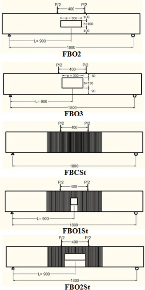
PECIMENS DESCRIPTIONIn this study, nine pretensioned prestressed concrete beams were made and tested, two of which were without openings as a control beams (one without and the other with strengthening by CFRP sheets), three were with openings, and the remaining four with openings and strengthened with CFRP sheets. The prestressed concrete beams designed according to ACI code 318-2011[14] class C. In all beams specimens the cross section was (b=130mm, H=300mm), the overall length was 2000mm, with clear span 1800mm and shear span 700mm. One strand Φ15.24mm (7-wire) and (2Φ12mm) diameter used as longitudinal reinforcement at bottom and (2Φ12mm) diameter bars used as longitudinal reinforcement at top to resist tension stresses at initial stage. The flexure prestressed beams designed with extra strength in shear ( used Φ10mm stirrups at 70mm center to center) to ensure flexure failure even after strengthening as shown in Figure(6). Strengthening system was chosen carefully according to some considerations, mainly, crack pattern around of opening and mode of failure. Five beams prepared and strengthened with CFRP sheets as shown in Figure (7). The beams FBCSt, FBO1St, FBO2St and beam FBO3St were strengthened in tension zone with one layer of longitudinal CFRP (width 130 × length 800)mm and in compression zone with full wrap CFRP (width 800)mm, while the beam FBO3StC was strengthened in compression zone only with full wrap CFRP (width 300)mm at top chord of opening. More details for the beams specimens were shown in Figure (7) and Table (5).
FIGURE (6)REINFORCEMENT DETAILS OF BEAMS SPECIMENS.ALL
DIMENSIONS IN MM AND ALL COVERS 20MM.
165 Figure (7) Specimens Description of Flexure Prestressed Beams.
All Dimension in mm.
Table (5) Symbols of Flexure Prestressed Beams
Symbols Refer to
FBC Flexure Beam Control.
FBO1 Flexure Beam with square Opening No. 1 (w=100 × h=100) mm at mid span of beam.
FBO2 Flexure Beam with rectangular Opening No. 2 (w=300 × h=100) mm at mid span of beam.
FBO3 Flexure Beam with rectangular Opening No. 3 (w=300 × h=150) mm at mid span of beam.
FBCSt Flexure Beam Control and Strengthened with CFRP.
FBO1St
Flexure Beam with square Opening No. 1 (w=100 × h=100) mm at mid span of beam and Strengthened with CFRP.
FBO2St
Flexure Beam with rectangular Opening No. 2 (w=300 × h=100) mm at mid span of beam and Strengthened with CFRP.
FBO3St
Flexure Beam with rectangular Opening No. 3 (w=300 × h=150) mm at mid span of beam and Strengthened with CFRP.
FBO3StC
Flexure Beam with rectangular Opening No. 3 (w=300 × h=150) mm at mid span of beam and Strengthened with CFRP at Compression zone only.
6
P
REPARATION OFT
ESTS
PECIMENS6.1CONCRETE MIX PROPORTIONS
High strength concrete was used to cast all prestressed beams used in the test program. The mix was proportioned by weight at (1: 1.67: 2.67) and 0.3 for cement, sand, gravel and water/cement ratio respectively. One Liter from admixture (Hyperplast PC260) was used in concrete for each 100Kg of cement mixed to obtain early high compressive strength.
6.2FABRICATION
Nine steel forms were fabricated. The forms prepared as a rectangular-section with internal dimensions of 300mm height, 130mm width and 2000mm length, also painted with gray oxide primer to prevent rust. The steel gates of forms were drilled with holes of 20mm for passing strand (Ф15.24 mm) in all forms. The forms welded at the base plate of girders stand of girders factory in Karbala Company. Also the openings made from solid wood.
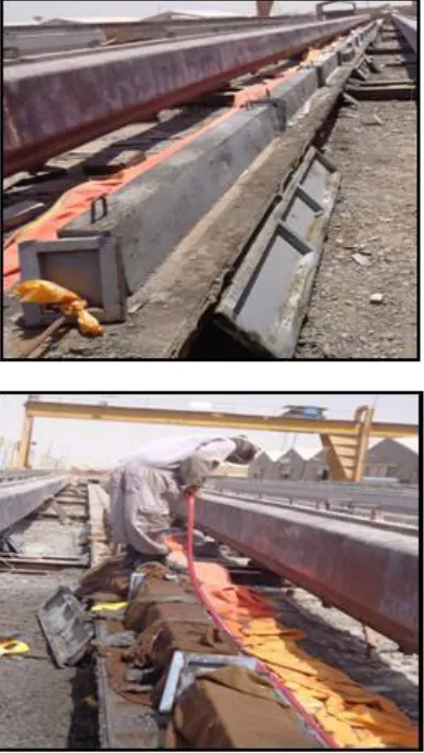
6.3PULLING OF STEEL STRAND
After placing reinforcement bars and solid wood for each specimen in their correct positions, one of steel strand Ф15.24 mm (7-wire) passed through holes of steel gates of forms and pulled at jacking force (305 bar or 130kN) as shown in Figure (8).
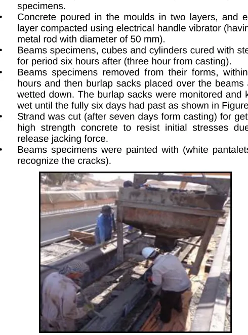
6.4CONCRETE CASTING AND CURING
Nine beams specimens, as shown in Figure (9), were casted and cured in Karbala Company for Fabrication of Pre-Cast Building. Nine standard cubes (150x150) mm and nine standard cylinders (200x100) mm were casted from the concrete. The concrete casting and curing procedures are: • Beams specimens, cubes and cylinders treated with oil
before putting the reinforcement cage or casting control specimens.
• Concrete poured in the moulds in two layers, and each layer compacted using electrical handle vibrator (having a metal rod with diameter of 50 mm).
• Beams specimens, cubes and cylinders cured with steam for period six hours after (three hour from casting). • Beams specimens removed from their forms, within 24
hours and then burlap sacks placed over the beams and wetted down. The burlap sacks were monitored and kept wet until the fully six days had past as shown in Figure(9). • Strand was cut (after seven days form casting) for getting high strength concrete to resist initial stresses due to release jacking force.
• Beams specimens were painted with (white pantalets to recognize the cracks).
Figure (9) Casting of Concrete, Removed Forms from Beams Specimens and Curing by Burlap Sacks.
6.5 SURFACE PREPARATION
At any strengthened member, the most fundamental part is the bond between the surface of member and CFRP sheets. Appropriate bond ensures that the load carried by the structural member is carried effectively to the CFRP sheets. Before applying CFRP sheets on the beams, the surface of concrete beam was grinded by using an electrical grinder to get a clean suitable surface and exposing the aggregate, free of all flaws, as shown in Figure (10). The edge of the beam was rounded (approximately 10 mm) to prevent stress concentration in the CFRP sheets.
Figure (10) Concrete Surface Preparation by Electrical Grinder.
6.6 APPLICATION OF CFRP SYSTEM
External strengthening followed the procedure recommended by the manufacturer which is described below:
• Mix part A and B together according to manufacturer technical data by slow speed electrical drill till it becomes grey color.
• Apply a thin layer of mixed epoxy on the concrete surface (approximately 1.5 mm) this will impregnate the carbon fiber sheet after they are placed on the concrete element. • Apply a coat of mixed epoxy on the clean carbon fiber
sheet.
• Place carbon fiber sheet on the concrete surface over the area that was previously coated with epoxy.
• Use a ribbed roller with direction of the sheet to remove air bubbles that are trapped behind the carbon fiber sheet.
• After the CFRP installation was complete, the CFRP strips were cured at ambient temperature for at least 7 days before testing.
Figure (11) shows the procedure of application CFRP system on concrete element.
Figure (11) Cutting CFRP Sheet, Apply Epoxy on CFRP and Concrete, Placing CFRP on Concrete, and Eliminating Air
167 Figure (11)Cutting CFRP Sheet, Apply Epoxy on CFRP and
Concrete, Placing CFRP on Concrete, and Eliminating Air Bubble.
7
I
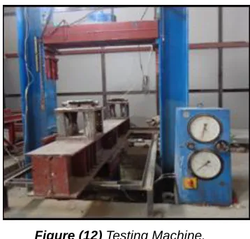
NSTRUMENTATION AND TEST SETUPAll beams were tested in a universal testing machine in the Structural Laboratory of College of Engineering in Kufa University as shown in Figure (12), with maximum capacity of 2000 kN. All the beams were tested under simply supported conditios with an effective span length of 1800mm rested on stiff steel frame and loaded with two-point loads applied and distributed across the entire width of the beams by using a solid I-beam (600×50) mm. The beams were tested under static loads, loaded in successive increments up to failure. To note crack development, prestressed concrete beams were painted with white pantalets before testing. After the preparations were finished and the initial readings of the demec discs were taken, the load was applied in small increments and the readings of deflection were taken every 5kN. At each increment the manual measurements were recorded, which included the applied load, deflection, crack width, concrete and CFRP strip strains. The cracks were outlined by thick marker pen and the beam specimens photographed.
Figure (12) Testing Machine.
8
T
ESTING THEP
ROPERTIES OFC
ONCRETE8.1 COMPRESSIVE STRENGTH TEST
The compressive strength test was determined according to BS. 1881: Part 116:1989 [15]. Cubes of (150×150) mm were tested by using a hydraulic compression machine of (2000) kN in the Structural Laboratory of College of Engineering of Kufa University. The average of three cubes was adopted at each tests, test was conducted at ages of 1 day, 7 days, and at specimens test time, as shown in Table (6).
Table (6) Test Results for Concrete Cubes.
Cubes (150 × 150 × 150)mm
Ultimate Compressive
Strength, MPa
*Compressive Cylinder Strength, MPa
**Modulus of Elasticity,
MPa
Average of All Specimens
1 days (steam curing)
38.9 31.12 25420.72
7 days (cutting
of strand)
52.1 41.7 28339.1
At test
time 60.08 48 29901.6
*
**
8.2 SPLITTING TENSILE STRENGTH
The splitting tensile test was carried out with (ASTM C496-2004) [16] specification cylinders of (100×200) mm were tested by using a hydraulic compression machine of (2000)kN in the Structural Laboratory of College of Engineering of Kufa University. The average of three cylinders was taken at each test, test was conducted at ages of 1 day, 7 days, and at specimens test time, as shown in Table (7).
' '
8
.
0
cuc
f
f
6900
3320
'
cc
f
0 40 80 120 160 200 240 280 320
0 2 4 6 8 10 12 14 16
Mid Span Deflection (mm)
A
p
p
li
e
d
L
o
a
d
(
k
N
)
FBC
0 40 80 120 160 200 240 280 320
0 2 4 6 8 10 12 14 16
Mid Span Deflection (mm)
A
p
p
li
e
d
L
o
a
d
(
k
N
)
FBC
FBO1
0 40 80 120 160 200 240 280 320
0 2 4 6 8 10 12 14 16 18
Mid Span Deflection (mm)
A
p
p
li
e
d
L
o
a
d
(
k
N
)
FBC FBO2 Table (7) Test Results for Concrete Cylinders for Calculation
Splitting Tensile Strength.
Cylinder ( 100× 200)mm Splitting Tensile Strength
Average of All Specimens
1 days
(steam curing) 3.17 7 days
(cutting of strand) 3.67
At test time 4.02
9
R
ESULTS AND DISCUSSION9.1 LOAD-DEFLECTION RESULTS
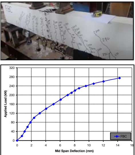
First flexural crack for control beam (FBC) observed at mid span at an applied load of (90kN) (32.73% of ultimate load). Some of flexural cracks at the mid of shear span changed their direction and propagated towards the nearest loading point, which was called flexure-shear crack. With increasing load, flexure cracks formed and increased in width, depth and number as shown in Figure(13). Beam FBC reached an ultimate load at (275kN) with flexure mode of failure (compression failure). Also Figure(13) shows relationship between the deflection and load at mid span for beam FBC.
Figure (13 ) Crack Patterns and Load-Deflection Curve for Beam FBC.
For beams FBO1 and FBO2 , the first flexural crack observed at the bottom of beam under the point load and at edge of opening respectively at an applied load of (75kN) (28.85% of ultimate load). When the applied load reached approximately (240kN), flexure cracks observed at top chord of opening for beam FBO2. The beams FBO1 and FBO2 failed by crushing of the compression zone (flexural failure) at ultimate load (260kN) as shown in Figures (14) and (15) respectively. The load-deflection curve for beams FBO1 and FBO2 are shown
in Figures (14) and (15) respectively. The opening in beams FBO1 and FBO2 reduced the load capacity at the same value compared with the solid beam FBC by (5.5%) because the depth of opening in both beams was constant ( h=100 mm and h/H=0.33) which did not affect the depth of compression zone. But the load-deflection curve for beam FBO2 was slightly greater than beam FBO1 due to the increase in width of opening in beam FBO2.
Figure (14 ) Crack Patterns and Load-Deflection Curve for Beam FBO1.
169
0 40 80 120 160 200 240 280 320
0 2 4 6 8 10 12 14 16
Mid Span Deflection (mm)
A
p
p
li
e
d
L
o
a
d
(
k
N
)
FBC
FBO3
0 40 80 120 160 200 240 280 320
0 2 4 6 8 10 12 14 16 18 Mid Span Deflection (mm)
A
p
p
li
ed
L
o
ad
(
kN
)
FBC FBO1 FBO2 FBO3
0 40 80 120 160 200 240 280 320
0 2 4 6 8 10 12 14 16 18
Mid Span Deflection (mm)
A
p
p
li
e
d
L
o
a
d
(
k
N
)
FBC FBCSt The first flexural crack noted at the bottom of beam at edge of
opening at an applied load of (55kN) (29.89% of ultimate load), as shown in Figure (16). When the applied load reached approximately (90kN), flexure-shear cracks directed and propagated toward the loading point. Also at load (180kN), flexure-shear cracks reached at depth equal to top of opening. The beam FBO3 failed by crushing the compression zone (flexural failure) at ultimate load (184kN). The load-deflection curve for beam FBO3 is explained in Figure (16). It can be concluded that rectangular opening reduced the flexural strength when compared with that beam FBC by about (33.1)%.
Figure (16 ) Crack Patterns and Load-Deflection Curve for Beam FBO3.
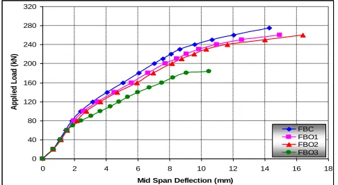
The opening in beams FBO2 and FBO3 reduced the load capacity compared with the solid beam FBC by (5.5%) and (33.1%) respectively, as shown in Figure (17). Beam FBO2 was higher in the ultimate load than the beam FBO3 by (27.6%) because of the difference in depth of opening in both beams
Figure (17 ) Load-Deflection Curve for Beams FBC, FBO1, FBO2 and FBO3.
(h=100 mm and h/H=0.33 for beam FBO2 and h=150 mm and h/H=0.5 for beam FBO3) which lead to a decrease in the depth of compression zone. Also the load-deflection curve for beam FBO3 was greater than beam FBO2 due to the increase in depth of opening causing reduction in stiffness of beam, as shown in Figure (17). For beam FBCSt, the first visible crack was flexural crack at load (120kN) (39.34% of ultimate load) at the end of full wrap CFRP sheet. The shear crack observed at mid shear span at applied load (170 kN). With the increase load, flexure and shear cracks formed and increased in width, depth and number. The beam FBCSt failed at load (305kN) by cutting CFRP sheet at compression zone (top) and tension zone (bottom) as shown in Figure (18). The ultimate load of beam FBCSt improved about (10.91%) than beam FBC. Also the deflection for beam FBCSt was lower than for beam FBC at pre-cracking and post-cracking stages because of strengthening by CFRP that increased stiffness of beam as shown in Figure (18).
Figure (18 ) Crack Patterns and Load-Deflection Curve for Beam FBCSt.
For beams FBO1St and FBO2St, the first flexural crack appeared at load of (100kN) at mid span of the beam at bottom chord of opening. The beams FBO1St and FBO2St failed at the load (295kN) and (294kN) respectively, by debonding CFRP sheet at the top of beam (compression zone) and cutting CFRP sheet at mid span of bottom beam (tension zone) as shown in Figures (19) and (20).The ultimate load of beam FBO1St increased approximately (7.27%) and (13.46%) than beams FBC and FBO1 respectively, and also the load-deflection curve of beam FBO1St stiffer than beams of FBC and FBO1, as shown in Figure (19). While the ultimate load of beam FBO2St improved approximately (6.91%) and (13.08%) with respect to
CFRP cutting
0 40 80 120 160 200 240 280 320
0 2 4 6 8 10 12 14 16 18
Mid Span Deflection (mm)
A
p
p
li
e
d
L
o
a
d
(
k
N
)
FBC FBO1 FBO1St
0 40 80 120 160 200 240 280 320
0 2 4 6 8 10 12 14 16 18 20 Mid Span Deflection (mm)
A
p
p
li
e
d
L
o
a
d
(
k
N
)
FBC FBO2 FBO2St
0 40 80 120 160 200 240 280 320
0 2 4 6 8 10 12 14 16
Mid Span Deflection (mm)
A
p
p
li
e
d
L
o
a
d
(
k
N
)
FBC FBO3 FBO3St beams FBC and FBO2 respectively, and also the
load-deflection curve of beam FBO2St more stiffer than of beam FBO2 as shown in Figure (20).
Figure (19 ) Crack Patterns and Load-Deflection Curve for Beam FBO1St.
Figure (20 ) Crack Patterns and Load-Deflection Curve for Beam FBO2St.
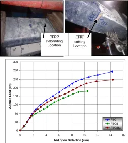
For beam FBO3St, the first flexural crack noted at load of (90kN) (37.97% of ultimate load)at bottom chord of opening. The beam FBO3St failed at the load (237kN), by debonding CFRP sheet at the top of beam (compression zone) and cutting CFRP sheet at mid span of bottom beam (tension zone) as shown in Figure (21). The ultimate load of beam FBO3St was less about (13.82%) and increased about (28.8%) with respect to beams FBC and FBO3 respectively. Also the load-deflection curve of beam FBO3St was stiffer than beam FBO3, but it was softer than beam FBC as shown in Figure (21).
Figure (21 ) Crack Patterns and Load-Deflection Curve for Beam FBO3St.
For beam FBO3StC, the first flexural crack started at load of (70kN) (30% of ultimate load) at mid span of beam at bottom chord of opening as shown in Figure (22). The first crack of beam FBO3StC was higher than the beam FBO3 (55kN) because the opening was strengthen by full wrap CFRP sheet in compression zone, but The first crack of beam FBO3StC was lower than beam FBO3St (90kN) because the opening in the beam FBO3St was strengthen by full wrap CFRP sheet in compression zone and one layer of longitudinal CFRP sheet in tension zone. This means using longitudinal CFRP sheet in tension zone delayed the first crack. At the applied load reached (230kN), CFRP sheet began to debond at top beam (compression zone). The beam FBO3StC failed at the load (233kN), by cutting CFRP sheet at the top chord of opening (compression zone) as shown in Figure(22). The ultimate load of beam FBO3StC was less about (15.27%) and increased about (26.63%) with respect to beams FBC and FBO3 respectively. Also the load-deflection curve of beam FBO3StC was stiffer than beam FBO3, but it was softer than beam FBC. The maximum deflection of the beam FBO3StC was equal to (18.5) mm as shown in Figure (22).
CFRP cutting Location CFRP Debonding
Location
CFRP cutting Location CFRP
Debonding Location
CFRP Debondin
g Location
171
0 40 80 120 160 200 240 280 320
0 2 4 6 8 10 12 14 16 18 20
Mid Span Deflection (mm)
A
p
p
li
e
d
L
o
a
d
(
k
N
)
FBC FBO3 FBO3StC
0 40 80 120 160 200 240 280 320
0 2 4 6 8 10 12 14 16 18 20
Mid Span Deflection (mm)
A
p
p
li
e
d
L
o
a
d
(
k
N
)
FBC FBO1 FBO2 FBO3 FBCSt FBO1St FBO2St FBO3St FBO3StC
0 40 80 120 160 200 240 280 320
0 0.2 0.4 0.6 0.8 1 1.2 1.4 1.6
Max Crack Width (mm)
A
p
p
li
e
d
L
o
a
d
(
k
N
)
FBC FBO1 FBO2 FBO3 Figure (22 ) Crack Patterns and Load-Deflection Curve for
Beam FBO2StC.
The strengthening system used in beams FBO1St and FBO2St increased the ultimate load approximately (7.27%) and (6.91%) respectively with respect to the solid beam FBC, which means, this strengthening system removed the effect of opening within ratio (h/H = 0.33) as shown in Figure (23). Also Figure (23) shows beams FBO1St and FBO2St to be slightly stiffer than the solid beam FBC, while FBO1St and FBO2St were very stiffer than FBO1 and FBO2 respectively. Therefore, this result gave a good indication about using CFRP in the improvement deflection. The strengthening system used in beams FBO3St and FBO3StC increased the ultimate load about (28.8%) and (26.63%) respectively with respect to the beam FBO3, but the ultimate load of beams FBO3St and FBO3StC was less than solid beam FBC about (13.82%) and (15.27%) respectively, which means, this strengthening system removed the effect of opening partially within ratio (h/H = 0.5) as shown in Figure (23). The strengthening system of compression and tension zone for opening delayed the cracking load, increased the ultimate load slightly and decreased the deflection greatly comparing with strengthening system of compression zone only as shown in Figure (23).
Figure (23) Load-Deflection Curve for All Flexural Prestressed Beams.
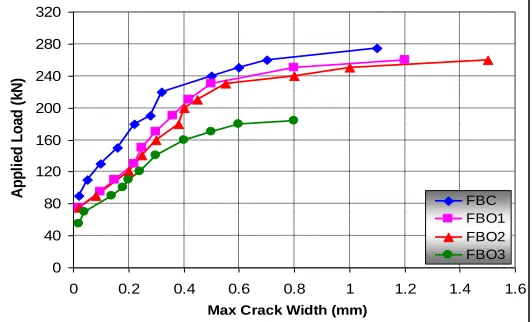
9.2CRACK WIDTH RESULTS
The crack width for flexure beams shown in Figures (24) and (25), the crack measured for not located point for all tested beams with sequence of loading, which searched and checked, for the crack that has max width between all the appeared cracks. In general, all cracks that measured as flexural cracks and located include a flexure and flexure-shear region.
Figure (24) Crack Width Versus Applied Load for Flexure Beams Without Strengthening by CFRP.
0 40 80 120 160 200 240 280 320
0 0.4 0.8 1.2 1.6 2 2.4
Max Crack Width (mm)
A
p
p
li
e
d
L
o
a
d
(
k
N
)
FBC FBCSt FBO1St FBO2St FBO3St FBO3StC
Figure (25) Crack Width Versus Applied Load for Flexure Beams With Strengthening by CFRP.
10
C
ONCLUSIONSThe most important conclusions that can be drawn from the present paper are:
1. The presence of opening in the flexure prestressed beams at mid span decreased the ultimate load about (5.5%) (if square or rectangular opening with ratio h/H=0.33) when compared with flexure prestressed beam without openings.
2. It was noted that the presence of rectangular opening with ratio h/H=0.5 in flexure prestressed beams at mid span decreased the ultimate load about (33.1%) when compared with flexure prestressed beam without openings.
3. The externally strengthened flexural prestressed concrete beams with bonded CFRP sheets showed a significant increase in ultimate loads, this increase was about (10.9-28.8)% when compared with the unstrengthened beams 4. The use of CFRP sheets as external strengthening had a
significant effect on crack pattern of the flexural prestressed concrete beams with openings by delaying the crack appearance and reducing the crack width at the same load value. The increase in cracking loads was about (27.3-63.6)% as compared with the unstrengthened beams.
5. The load-deflection curves for flexure prestressed beams strengthened with CFRP sheets were stiffer than the unstrengthened beams. Therefore, this result gave a good indication about using CFRP sheets in improving deflection.
6. It was noted that the strengthening system used in flexural prestressed beams removed the effect of opening completely within ratio (h/H = 0.33) , while it removed the effect of opening partially for flexural prestressed beams contained openings within ratio (h/H = 0.5).
R
EFERENCES[1] Nilson, A.H. (1987), “Design of Pestressed Concrete”, Second Edition.
[2] Mansur, M.A., and Tan, K.H. (1999) “Concrete Beams with Openings Analysis and Design”, First Edition.
[3] Prentzas, E.G. (1968), “Behavior and Reinforcement of Concrete Beams with Large Rectangular Apertures”, Ph.D.
Thesis, University of Sheffied, U.K. Sept, 230 pp. .
[4] Mansur, M.A. and Hasnat, A. (1979), “Concrete Beams with Small Openings under Torsion”, Journal of the Structural Division, ASCE, Vol. 106, ST 11, Nov., pp. 2433-2447.
[5] Somes, N.F. and Corley, W.G. (1974), “Circular Openings in Webs of Continuous Beams Shear in Reinforced Concrete”, Special Publication SP-42, American Concrete Institute, Detroit, pp. 359-398.
[6] Abdalla, H. and Kennedy, J.B. (1995), “Design Against Cracking at Openings in Prestressed Concrete Beams”, PCI Journal, Vol. 40, No. 6, Nov.-Dec., pp. 60-75.
[7] Savage, J.M., Tadros, M.K., Arumugasaamy, P., and Fischer, L.G. (1996), “Behavior and Design of Double Tees with web Openings”, PCI Journal, Vol. 41, No. 1, Jan.-Feb., pp 46-61.
[8] Iraq Specification No. 5 (1984), “Portland Cement”, Baghdad.
[9] Iraq Specification No. 45 (1984) , “Natural Sources for Gravel that is Used in Concrete and Construction”, Baghdad.
[10]ASTM C494 (2005), “Standard Specification for Chemical Admixtures for Concrete”, ASTM Standard C494, American Society for Testing and Materials, West Conshohocken, Pennsylvania.
[11]ASTM A370 (2005), “Standard Test Method and Definition for Mechanical Testing of Steel Products”, ASTM Standard A370, American Society for Testing and Materials, West Conshohocken, Pennsylvania.
[12]ASTM A416M (2005) “Standard Specification for Steel Strand, Uncoated Seven-Wire for Prestressed Concrete”, ASTM Standard A416M, American Society for Testing and Materials, West Conshohocken, Pennsylvania.
[13]ACI Committee 440 (2008), “Guide for the Design and Construction of Externally Bonded FRP Systems for Strengthening Concrete Structures”, (ACI 440.2R-08) American Concrete Institute, Farmington Hills.
[14]ACI Committee 318M (2011), “Building Code Requirements for Structural Concrete (ACI 318-11) and Commentary (ACI 318R-11)”, American Concrete Institute, Farmington Hills.
[15]BS 1881: Part 116 (1989), “Method for Determination of Compressive Strength of Concrete Cubes”, British Standards Insitution.
![Figure (3) Openings Shapes Considered by Prentazs [3].](https://thumb-us.123doks.com/thumbv2/123dok_us/9051468.1441051/2.612.313.589.542.698/figure-openings-shapes-considered-prentazs.webp)