DESIGN OF A HIGH SPEED MULTIPLIER USING
SIGNED AND UNSIGNED NUMBERS FOR ALU
PROCESSOR OPERATION
Bollimuntha Bhanu Prasad
1, P.V.L Siva Prasad
2, L.Srinivas Reddy
3 1M.Tech Scholar (VLSI), Nalanda Institute of Engg and Tech. (NIET),
Siddharth Nagar, Guntur, A.P. (India)
2
Asst. Professor (ECE), Nalanda Institute of Engg and Tech. (NIET),
Siddharth Nagar, Guntur, A.P. (India)
3
Assistant. Professor (ECE), Nalanda Institute of Engg and Tech. (NIET),
Siddharth Nagar, Guntur, A.P. (India)
ABSTRACT
This article presents the design and implementation of Advanced Modified Booth Encoding (AMBE) multiplier.
This multiplier works for both signed and unsigned 32 - bit number’s multiplication. As compared this proposed
technique with the existed methods, these existed methods like Modified Booth Encoding Multiplier and the
Baugh-Wooley multiplier performs multiplication operation on signed numbers only, where as the array
multiplier and Braun array multipliers will perform the multiplication operation on unsigned numbers only.
Accordingly, the necessity of the modern computer system is a out-and-out and very high speed exceptional
multiplier unit for signed and unsigned numbers. For that reason, this paper presents the design and
implementation of AMBE multiplier. The modified Booth Encoder circuit creates half the partial products in
parallel. To generate an additional partial product of the AMBE multiplier, we need to expand sign bit of the
operands. In proposed technique, the Carry Save Adder (CSA) tree and the final Carry Look ahead (CLA) adder
are used to speed up the multiplication process. By this we can understand easily that the multiplier can reduces
two chip’s hardware area and it turns to reduce the power consumption and also reduces cost.
Keywords
—
Advance Modified Booth Encoding, Signed-Unsigned Bits, Neg Bit, Partial Product
Reduction Tree,
I. INTRODUCTION
Multiplication is a most often used operation in various computing systems. Actually multiplication process is
done by using addition because, multiplicand adds to multiplier no. of times to provide the multiplication value
between multiplier and multiplicand. But the fact is considering that this type of implementation needs huge
hardware resources and the circuit functions at absolutely low speed. In order to tackle this, so many ideas have
been offered thus far for the last three decades. Every coming technique mainly aimed at improvement in
particular thing according to the present requirements. One of those may be aimed at high clock speeds and
another aimed for low power or less area factors. There is the need of one special and efficient architecture is to
satisfy main factors of VLSI say speed, area and power. In those three, area and power has controlled by
multiplication operation that involves two steps one is generating partial products and adding these partial
products as the procedure of technique. From this it is confirm that need of a system which generates partial
products as fast as possible and add these products speedily. This speed factor can be achieved by minimizing
the count of developing the partial products. The Booth‟s algorithms are intended for this special feature. Here
we need adder architectures which can able to make speed addition in between those partial products. Hence, we
can strongly say that the multipliers create significant impact on the whole system. For this many high
performance based algorithms and architectures were proposed and especially very high speed multipliers uses
in vector and pipeline computers.
Most of the digital signal processing applications like multimedia and communications systems uses high speed
and pipelined Booth multipliers. High speed DSP processing applications for instance Fast Fourier transform
(FFT) involve multiplications and additions. The conventional modified Booth encoding (MBE) creates an
asymmetrical partial product array. This happens because of the least significant bit position of each partial
product row has the extra partial product bit. One article named “Design of High-speed Modified Booth
Multipliers Operating at GHz Ranges” shows a simple approach to create a regular partial product array with
less number of partial product rows and negligible overhead, by this means can able to lesser the complexity of
partial product reduction and diminishing the design area, delay, and power consumption of MBE multipliers.
Everything is good but the main negative aspect of this multiplier is that it functions only for operands, which is
of signed number.
The modified-Booth algorithm is comprehensively used for high-speed multiplier circuits. The reduced number
of created partial products extensively improves multiplier performance when these array multipliers were used.
One different approach is for signed applications i.e., Baugh-Wooley algorithm, but is not so widely accepted
because it may be complex to arrange on irregular reduction trees.
As we are discussed that the Baugh-Wooley algorithm is operates on signed numbers only. The Braun array
multipliers and the array multipliers are used for unsigned numbers only. Hence, the requirement of new
algorithm needs to satisfy the factors of high speed multipliers and can perform the multiplication process on
signed as well as unsigned numbers. In this article, we are presenting a new approach which can able to perform
the multiplication for both signed and unsigned numbers i.e., Advanced Modified Booth‟s Algorithm (AMBA).
II. CONVENTIONAL MODIFIED BOOTH MULTIPLIER
2.1 Algorithm
Multiplication process involves in three steps: 1) the first step is to create the partial products 2) the next step is
to add those produced partial products until the last two rows are remained and 3) the third and last step is to
work out the final multiplication outcome by adding the last two rows. In the first step, the modified Booth
algorithm decreases the number of partial products by half. The efficient booth‟s encoding and decoding scheme
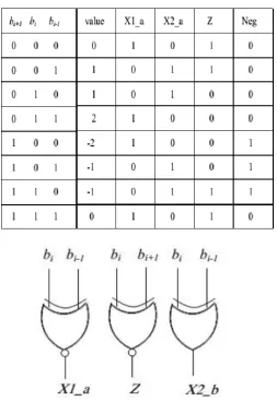
i.e., modified booth encoding scheme has shown in fig 1. Table I is shows the rules to create the conceded
signals based on MBE scheme. Logic diagrams of encoder and decoder is shown in fig 1 (a) and fig 1 (b)
Fig 1(A): Simple Encoder And Fig 1(B): Decoder Of MBE Scheme
TABLE I: Truth Table of MBE Scheme
Table I has shown us the truth table of MBE encoder scheme. The Z signal can make the output zero to gives
back the incorrect X2_b and Neg signals. The three x-signals have encoded and will generate X1_b,X2_b, and
Z signals. To derternine the Neg_cin and Row_LSB, we need to combine the y LSB signal (LSB of the y signal)
with x-signals. The sign extension signals can determine by combining the y MSB and x-signals.
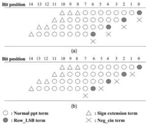
Fig 2: 8×8 MBE Partial Product Array
To reduce the number of partial product rows by half, fig 2 (a) has approved for parallel multipliers. Thus, we
can reduce the size and speeding up the performance. From fig 1 (a), the algorithm generates n/2 +1 partial
product rows in place of n/2 because of the extra partial product bit called as neg bit at the position of least
significant bit of each and every partial product. It shows negative ending and makes it an irregular partial
product array, by this the reduction tree becomes complex.
Fig 3: Generated Partial Products and Sign Extension Scheme
Hence, new approach has come into exist. As like in fig 3, the modified booth multipliers with a regular partial
product array produces very regular partial product array. In this method, the neg bit is shifted left and replaced
the place with ci, where the last neg bit is removed. This approach can able to reduce the partial product rows
from n/2 +1 to n/2. It has done by incorporating the last neg bit into the sign extension bits of the first partial
product row. Here, almost no overhead is initiated to the partial product generator. The partial products
generated by the modified Booth‟s algorithm and these are added by using the Wallace tree until the last two
rows are remained.
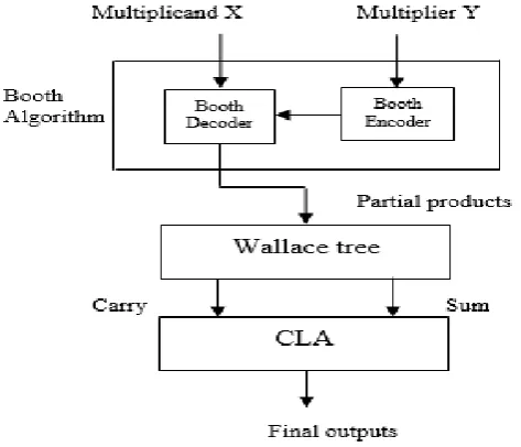
2.2 Architecture
Fig 4 shows us the architecture of modified booth‟s algorithm. Two inputs of the multiplier are multiplicand „X‟ and multiplier „Y‟. As per the modified booth encodes the multiplier „Y‟ and derives the encoded signals as
shown in fig 1 (a). By using fig 1 (b), the booth makes decoding operation using the encoded signal and the
input signal „X‟. After generation of partial products, we need to decrease the partial products until two. These
two are added for the final result by using the carry look-ahead (CLA) adder.
III. PROPOSED AMBE MULTIPLIER
The main target of this article is designing of 32×32 multiplier, which can able to perform both signed and
unsigned multiplications using MBE. Truth table for the proposed technique is shown in TABLE II. Logic
diagram for the proposed project has drawn in fig 5. The Boolean expression for one bit partial product
generator has stated in equation 1 by using MBE logic and other conditions.
TABLE II: Truth Table for Modified Scheme
Fig 5: Logic Diagram for Proposed Encoder
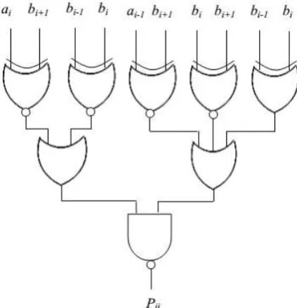
Fig 6 gives us the clarification of generation of equation 1. The encoder and decoder operations have doesn‟t
consider as separate with one and other by the SUMBE multiplier, it constructed as one unit as shown in fig 6.
The negative partial products are renewed into 2‟s complement by adding together one negate (Ni) bit. One
negate bit expressed in equation 2. Logic diagram for negate bit has drawn in fig 7. By using the equations 3 and
4 our required extension is obtained, which is used to convert 2‟s complement signed multiplier into both signed
Fig 6: Logic Diagram of 1 Bit Parallel Product Generator
Fig 7: Logic Diagram of Negate Bit Generator
The effective principle of sign extension that changes signed multiplier to signed-unsigned multiplier as follows.
First we need to indicate whether the operation of multiplication is signed or unsigned, for that one bit control
signal called unsigned (s_u) bit is used. While the multiplication process is unsigned, the
signed-unsigned bit (s_u) is indicates 0 and if it is 1, the multiplication indicates signed. It is essential that when the
process is unsigned multiplication the sign extended bit of both multiplicand and multiplier must and should be
extended with 0 thus, a32= a33= b32= b33= 0. It is necessary that when the process of multiplication is signed,
the sign extended bit depends on three different aspects these are whether the multiplicand is negative or the
multiplier is negative otherwise both the operands are negative.
Consider that, the multiplier operand is positive and the multiplicand operand is negative then the generated sign
extended bits are s_u = 1, a31 = 1, b31 = 0, b32 = b33 = 0 and a32 = a33 = 1. Consider if the multiplier operand
is negative and the multiplicand operand is negative then the sign extended bits should be s_u = 1, a31 = 0, b31
= 1, b32 = b33 = 1 and a32 = a33 = 0. The operation of SUBME operation is shown in TABLE III.
TABLE III: The SUBME Operation
Sign- Unsign Type of operation
0
1
Unsigned multiplication
Signed multiplication
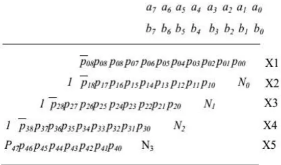
The partial products generated by the partial product generator (fig 6) are shown in fig 9. In that figure, we can
observe that 17-partial products with sign extension including negate bit Ni. All the 17-partial products are
created in parallel.
Fig 8: 8×8 Multiplier of Signed-Unsigned Number
Fig 9: 32X32 Multiplier for Signed-Unsigned Number
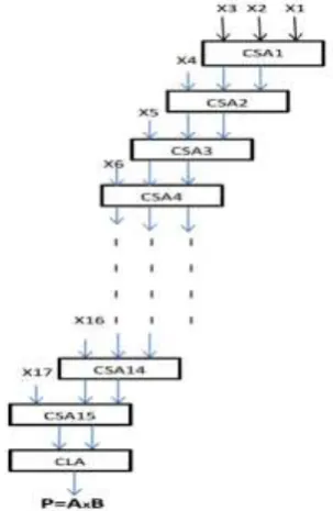
Here the 17 partial products are X1, X2, X3, X4, . . . , X16 and X17. These all are added up to final stage by
using the carry save adder (CSA) and the final stage we are going to use carry look-ahead adder (CLA). It is
drawn in fig 10. The CSA takes three inputs and produces two outputs say sum and carry. These two outputs
given to another CSA as inputs and the third input is taken from next one of the generated partial products. This
process continues up to all the partial products are considered. The final two outputs say sum and carry are
given to the CLA as inputs and it generates the output. We are assuming here that the delay of each gate is one
Fig 11: Partial product adder logic
IV. SIMULATION RESULTS
Here we are designing high speed multipliers with the modified booth encoding technique. This is yielding high
speed due to the booth encoding format. This multiplier is designed using Verilog HDL and simulated in the
V. CONCLUSION
The paper presents the high speed modified booth encoding architecture which reduces the hardware complexity
while generating partial products. The partial products will be reduced in fast manner by encoding scheme. This
design of Verilog has proved that this is enhancing the speed.
REFERENCES
[1] W. –C. Yeh and C. –W. Jen, “High Speed Booth encoded Parallel Multiplier Design,” IEEE transactions
on computers, vol. 49, no. 7, pp. 692-701, July 2000.
[2] Shiann-Rong Kuang, Jiun-Ping Wang, and Cang-Yuan Guo, “Modified Booth multipliers with a Regular
Partial Product Array,” IEEE Transactions on circuits and systems-II, vol 56, No 5, May 2009.
[3] Li-Rong Wang, Shyh-Jye Jou and Chung-Len Lee, “A well-tructured Modified Booth Multiplier Design”
978-1-4244-1617-2/08/$25.00 ©2008 IEEE.
[4] Soojin Kim and Kyeongsoon Cho “Design of High-speed Modified Booth Multipliers Operating at GHz
Ranges” World Academy of Science, Engineering and Technology 61 2010.
[5] Magnus Sjalander and Per Larson-Edefors. “The Case for HPM-Based Baugh-Wooley Multipliers,”
Chalmers University of Technology, Sweden, March 2008
[6] J. Fadavi-Ardekani, ªM×N Booth Encoded Multiplier Generator Using Optimized Wallace Trees,º IEEE
Trans. VLSI Systems, vol. 1,no. 2, June 1993.
[7] Wang, G., “A unified unsigned/signed binary multiplier”, TheThirty-Eighth Asilomar Conference on
Signals, Systems andComputers, 2004, Vol. 1, pp.:513 - 516, Nov 7-10, 2004.
[8] Kim J. Y., “Multiplier to selectively perform unsigned magnitude multiplication or signed magnitude
multiplication”,USpatent 5,870,322, Feb 9, 1999.
[9] Hwang-Cherng Chow and I-Chyn Wey, “A 3.3V 1GHz high speed pipelined Booth multiplier,” Proc. of
IEEE ISCAS, vol. 1, pp. 457-460, May 2002.
[10] M. Aguirre-Hernandez and M. Linarse-Aranda, “Energy-efficient high-speed CMOS pipelined multiplier,”
Proc. of IEEE CCE, pp. 460-464, Nov. 2008.
[11] A. D. Booth, “A signed binary multiplication technique,” Quarterly J. Mechanical and Applied Math, vol.
4, pp.236-240, 1951.
[12] Kuang S. R., Wang J. P., Guo C. Y., “Modified Booth Multipliers With a Regular Partial Product
Array”,IEEETransactions on Circuits and Systems II: Express Briefs,Vol.56, Issue 5, pp.:404 - 408, May,
2009
AUTHOR DETAILS
BOLLIMUNTHA BHANU PRASAD, Pursuing M.tech (VLSI) from Nalanda
institute of Engineering and Technology (NIET), Siddharth Nagar, Kantepudi village,
Satenepalli Mandal Guntur Dist.,A.P, INDIA. His area of interest includes high speed
P.V.L SIVA PRASAD, He received his master‟s degree in VLSI. His are of interest
include digital communications and VLSI system design working as Asst. professor
(ECE) from Nalanda institute of Engineering and Technology (NIET), Siddharth
Nagar, Kantepudi village, Satenepalli Mandal Guntur Dist.,A.P,
L.SRINIVAS REDDY, He completed his post-graduation in DECS. His area of
interest includes digital electronics, digital communication, digital system design and
VLSI technology and design. His research areas are optimal communication
technology. He is currently working as Asst.professor (ECE) from Nalanda institute of
Engineering and Technology (NIET), Siddhartha Nagar, Kantepudi village, Satenepalli