Global Journal of Advance Engineering Technologies and Sciences
ANALYSIS OF LINEAR ARRAY ANTENNA FOR SLL REDUCTION
USING SMART ANTENNAS
Pradeep Malviya, Prof. Giriraj Prajapati, Prof. A. C. Tiwari, Mr. Vijit Mishra
M. Tech. Scholar1, Asst. Prof.2, Prof.& HOD3Department of Electronics and Communication Engineering
Lakshmi Narain College of Technology, Indore (M.P.) India
ABSTRACT
In this thesis proposed a very simple and powerful method for the synthesis of linear array antenna. This method reduced the desired level of side lobe level (SLL) as well as to steer the main beam at different-different angle. A
new method for adaptive beam forming for a linear antenna arrays using genetic algorithm (GA) are also proposed.
Genetic Algorithm is an iterative stochastic optimizer that works on the concept of survival of the population values based on the fitness value. An adaptive genetic algorithm has been used in linear array to optimize the excitation levels of the elements resulting in a radiation pattern with minimum side lobe level. These algorithm can determinate the various values of side lobe level and phase excitation for each antenna to steer the main beam in specific direction.
Keyword
: Smart Antenna, Genetic Algorithm (GA), Side Lobe Level (SLL), Linear Array Antenna.INTRODUCTION OF SMART ANTENNAS
Smart antennas have recently been proposed as a solution to enhance the capacity of wireless communication systems for 3G network [1]. They are also considerably important because of their potential for decreasing interference, improving quality of service [2], enhancing power control and extending battery life in portable units. In an adaptive antenna system, beam forming algorithms the weight of antenna arrays can be adjusted to form certain amount of adaptive beam to track corresponding users automatically and at the same time to minimize interference arising from other users by introducing nulls in their directions[3]. Antennas are a very important component of communication systems. By definition, it is a device that converts guided electromagnetic waves into unguided ones and vice versa. Antennas demonstrate a property known as reciprocity, which means that an antenna will maintain the same characteristics regardless if it is transmitting or receiving.
It is the most efficient leadinginnovation for maximum capacity and improved quality andcoverage. Using beam forming algorithms the weight of antennaarrays can be adjusted to form certain amount of adaptivebeam to track corresponding users automatically and at thesame time to minimize interference arising from other users byintroducing nulls in their directions.
SMART ANTENNA CONSTRUCTION
Fig. 1 Consist of an array of antenna elements Smart Antenna Systems
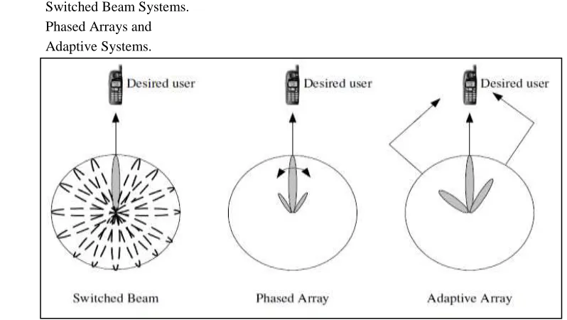
The basic idea of “smart” concept used for antenna systems, which are simple hardware elements, is the use of a digital signal-processing capability to transmit and receive in an adaptive, spatially sensitive manner. In other words, such a system can automatically change the directivity of its radiation patterns in response to its signal environment. In comparison with other antenna systems this technology can dramatically increase the performances (such as power consumption, capacity etc.) of a wireless system. The fundamental idea behind a smart antenna is not new but dates back to the early sixties when it was first proposed for electronic warfare as a counter measure to jamming [14]. Until recently, cost barriers have prevented the use of smart antennas in commercial systems. Thus in existing wireless communication systems, the base station antennas are either omni-directional which radiate and receive equally well in all azimuth directions, or sector antennas which cover slices of 60 or 90 or 120 degrees [15]. However, the advent of low cost Digital Signal Processors (DSPs), Application Specific Integrated Circuits (ASICs) and innovative signal processing algorithms have made smart antenna systems practical for commercial use. The smart antenna systems for cellular base stations can be divided into three main categories, which are illustrated in Figure 2.
Switched Beam Systems.
Phased Arrays and
Adaptive Systems.
Fig. 2 illustrated in Figure (a) Switched Beam Systems, (b) Phased Arrays and (c) Adaptive Systems.
PHYSICAL CONSTRUCTION OF ANTENNA
Antennas can be constructed in many different ways, ranging from simple wiresto parabolic dishes, up to coffee cans. When considering antennas suitable for 2.4 GHzWLAN use, another classification can be used. We identify two application categories which are Base Station and Point-to-Point. Each of these suggests different types of antennas for their purpose. Base Stations are used for multipoint access. Two choices are Omni antennas which radiate equally in all directions, or Sectorial antennas, The classification of antennas can be based on frequency/size and directivity.
FREQUENCY AND SIZE
Antennas used for HF are different from the ones used for VHF, which in turn are different from antennas for microwave. The wavelength is different at different frequencies, so the antennas must be different in size to radiate signals at the correct wavelength. We are particularly interested in antennas working in the microwave range, especially in the 2.4 GHz and 5 GHz frequencies. At 2.4 GHz the wavelength is 12.5 cm, while at 5 GHz it is 6 cm.
SIMULATION RESULTS ANALYSIS OF LINEAR ARRAY FOR SLL REDUCTION
This section gives the simulation result for various linear antenna array design obtained by GA technique. five linear array structures are assumed, each maintaining a fixed spacing between the elements. The antenna model consists of N elements equally spaced with distance of separation d = 0.5λ along the y-axis. In our investigation, there is an array of 5, 10, 15, 20, elements. Small number of elements is preferred in this work. The selection of number of elements depends on the designer’s choice based on the cost, size, aperture of the antenna, and speed of convergence. As the number of elements increases, the cost increases. Aperture increases and the performance gets improved. Various results for pattern generation for side lobe level is given in following table.
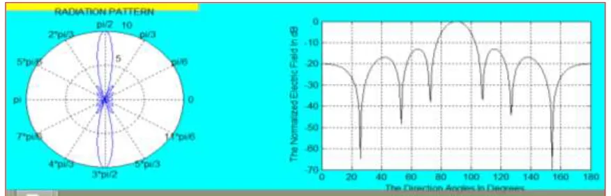
Figure 3: Radiation pattern with side lobe level of -12.04dB for N = 5 elements.
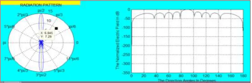
Figure 5: Radiation pattern with side lobe level of -13.14dB for N = 15 elements
Figure 6:Radiation pattern with SLL of -13.22 dB for N = 20 elements
Table 1: Results for Radiation Pattern with SLL
Figure Number Number of Element SLL (dB)
3 5 -12.04
4 10 -13.00
5 15 -13.14
6 20 -13.22
CONCLUSION
From the above simulation results, it can be clearly seen that for frequency f = 2GHz, spacing between the antenna
element is /2 , side lobe level is reduced from -13.2233 to -12.0417. In case of N=5, spacing between two element
is /2, directivity 10.3645, the SLL is -12.0417, for N = 10 spacing between two element is /2, directivity 14.19 the
SLL is -12.9732. In case of N = 15 spacing between two element is /2, directivity 16.1573 , SLL is -13.1308. In
case of N = 20 spacing between two element is /2, SLL is -13.2222.In case of N = 25 spacing between two element is /2, directivity 18.5064,SLL is -13.2.233.
REFERENCES
1. FreweyniKidane, TawatuAbreha, Dilip Mali “Smart Antenna Techniques for Interference Suppression in
WCDMA Using LMS Algorithm” TECHNIA – International Journal of Computing Science and
Communication Technologies, VOL.6 NO.1, July. 2013.
2. Mohammed A. Abdala and Areej K. Al-Zuhairy“Integration of Smart Antenna System in Mobile Ad Hoc
3. SurayaMubeenDr.Am.PrasadDr.A.Jhansi Rani “Smart Antenna its Algorithms and Implementation” 2012, IJARCSSE Volume 2, Issue 4, April 2012.
4. R.L.Haupt, “Thinned arrays using genetic algorithm”, IEEE Transaction on Antenna and Propagation,
Vol.12 Issue 7, pp 993-999 July1994.
5. R.L.Haupt, “Optimum quantized low sidelobe phase tapers for array”, IEEE Electronics Lett. 31(14)
pp1117- 1118 July 1995.
6. S.A. Babale, D.D. Dajab, “Synthesis of a Linear Antenna Array for Maximum Side-lobe Level
Reduction”International Journal of Computer Applications (0975 – 8887) Volume 85 – No 16, January 2014.
7. AniruddhaBasak, Siddharth Pal, Swagatam Das and Ajith Abraham, “Circular Antenna Array Synthesis with
a Differential Invasive Weed Optimization Algorithm”, 10th International Conference on Hybrid Intelligent
Systems (HIS 2010), Atlanta, USA (Accepted, 2010).
8. Siddharth Pal, AnniruddhaBasak, and Swagatam Das, Ajith Abraham, “Linear Antenna Array Synthesis with
Invasive Weed Optimization Algorithm”, International Conference of Soft Computing and Pattern
Recognition”, IEEE DOI 10.1109/SoCPaR.2009.42, 2009.
9. KarthickRamachandran, “Smart Antennas in 4G”,Innovative Systems Design and Engineering ISSN
2222-1727 (Paper) ISSN 2222-2871, Vol 3, No 2, 2012.
10. T.S.JeyaliLaseetha, Dr.R.Sukanesh, “Synthesis of Linear Antenna Array using Genetic Algorithm to
Maximize Sidelobe Level Reduction”, International Journal of Computer Applications (0975 – 8887) Volume
20– No.7, April 2011.
11. R.L.Haupt, “Adaptive Nulling With Weight Constraints”, Progress In Electromagnetics Research B, Vol. 26,
pp 23- 38, 2010.
12. M.A.Panduro, “Design of Non-Uniform Linear Phased Arrays using Genetic Algorithms To Provide
Maximum Interference Reduction Capability in a Wireless Communication System”, Journal of the Chinese
Institute of Engineers,Vol.29 No.7,pp 1195-1201(2006).
13. Stephen Jon Blank, “On the Empirical optimization of Antenna Arrays”, IEEE antenna and Propagation
Magazine, 47, 2, pp.58-67, April 2005.
14. C.L.Dolph, “A current distribution for broadside arrays which optimizes the relationship between beam
width and side-lobe level,”Proc IRE 34 pp.3335-348 June 1946.
15. Xiang_qianChe, Li Bian, “Low-Side-Lobe Pattern Synthesis of Array Antennas by Genetic Algorithm”
Scientific Research Fund of Heilongjiang Provincial Education Department 2008 IEEE.
16. Yu-Bo Tian,JianQian, “Improve the Performance of a Linear Array byChanging the Spaces Among Array
Elements in Terms of Genetic Algorithm” IEEE Transactions on Antennas and Propagation, VOL. 53, NO. 7,
JULY 2005.
17. F. Soltankarimi, J. Nourinia and Ch. Ghobadi, “Side Lobe Level Optimization in Phased Array Antennas
Using Genetic Algorithm”, ISSST A Sydney, Australia, 30 Aug. – 2 Sep 2004.
18. Lav R. Varshney and Daniel Thomas “Sidelobe Reduction for Matched Filter Range Processing”, IEEE
Radar Conference, 2003.
19. R.L.Haupt, “Synthesizing low sidelobe quantized amplitude and phase tapers for linear arrays using genetic
algorithm”s, ProcInte.Conf. Electromagnetics in Advanced Application, Torino, Italy, pp 221-224 Sept.1995.
20. C.L.Dolph, “A current distribution for broadside arrays which optimizes the relationship between beam
width and side-lobe level”,Proc IRE 34 pp.3335-348 June 1946.
21. AritraChowdhury et.al. “Linear Antenna Array Synthesis using Fitness-Adaptive Differential Evolution
Algorithm”, IEEE Congress on Evolutionary Computation (CEC) 2010 pp.1-8,DOI.2010.
22. Korany R. Mahmoud,et.al., “Analysis of Uniform Circular Arrays for Adaptive Beamforming Application
Using Particle Swarm Optimization Algorithm”, International Journal of RF and Microwave Computer–
Aided Engineering DOI 101.1002 pp.42-52.
23. R.S.Elliott, “Antenna Theory and Design”, Prentice-Hall, New York 1981.
24. Prasad K.D., Prasad manish, “Introduction to antenna and wave propagation” edition 2013-2014.
25. Robert J.Mailloux, “Phased Array Antenna Handbook”, Second Edition, Publishing House of Electronic