JADE: Zero-Knowledge Device Localization and
Environment Mapping for Millimeter Wave Systems
Joan Palacios
]‡, Paolo Casari
]?, Joerg Widmer
]]IMDEA Networks Institute, Madrid, Spain ‡Universidad Carlos III, Madrid, Spain
?
Corresponding author, email:[email protected]
Abstract—Device localization is a highly important function-ality for a range of applications. It is particularly beneficial in mmWave networks, where it can be used to reduce the beam training overhead and anticipate handovers between access points. In this paper, we present JADE, an algorithm that estimates the location of a mobile user in an indoor space without any knowledge about the surrounding environment (floor plan, location of walls and presence of reflective surfaces) or about the location and number of access points available therein. JADE leverages the beam procedure used in pre-standard and commercial mmWave equipment to estimate the angle-of-arrival of multipath components of the signal sent by visible access points. This information is then employed to localize the mobile user, estimate the position of access points and finally form a map of the environment. No radar-like ranging operations are required for this. Our results demonstrate that JADE can localize a user with sub-meter accuracy in the broad majority of the cases, and that it even outperforms localization algorithms that require full knowledge of the environment and access point positions.
Index Terms—Millimeter wave; localization; indoor; virtual anchors; mobility; simulation
I. INTRODUCTION
A fast, accurate and dependable location service is a funda-mental building block for a broad spectrum of applications and advanced services. These include augmented reality, assisted living [1], as well as more lay functions such as modifying the ringing profile of a cell phone in different contexts (classroom, park, home, etc.) or alerting two friends that happen to be located close-by [2]. Additionally, accurate localization and tracking can serve as a proxy for physical communication functions [3], such as beamforming, handovers and context switching. While outdoor positioning is addressed by a number of relatively established solutions, recent work [4] suggests that the problem of indoor localization is still far from being solved, and continues to be the subject of very active research. Indoor localization typically has no access to satellite-based localization technologies, and must rely instead on wireless communications to achieve a location fix [5].
The recent uptake of millimeter wave (mmWave) commu-nications in the 30–300 GHz band [6] and the appearance of commercial mmWave systems (typically at 60 GHz) suggests that this technology will play a major role in indoor positioning systems in the near future. In fact, several characteristics of mmWave propagation have important implications for localization. For example, mmWave propagation occurs in quasi-optical patterns, whereby reflections off boundary indoor surfaces and obstacles are subject to limited scattering [7], and the line-of-sight (LoS) component tends to be predominant
over non-LoS (NLoS) components even in the presence of ob-stacles [8]. In addition, according to the Friis equation, the path loss is typically 30 to 40 dB higher over typical link distances because of the very high frequency, which implies that LoS paths can typically be distinguished from NLoS paths. Such a high path loss demands directional communications [9], which can be realized through high-gain horn antennas or phased antenna arrays. The latter, in particular, can be integrated in laptops or smartphones thanks to the small antenna form factor given by the millimeter wavelength.
The discussion above suggests that classical localization methods [10] based on geometrical propagation assumptions are appropriate for mmWave scenarios [11]. However, the spe-cific characteristics of mmWave communications warrant the design of localization schemes aimed at exploiting these char-acteristics. Among others, the heavy attenuation of mmWave signals is expected to lead to much denser access point deployments than witnessed in WiFi networks. Moreover, due to the short wavelength and large bandwidth of mmWave signals, a single, even directional transmission may generate multiple reflected paths, which reach the intended receiver with different delays and angles of arrival (AoAs) [12]. This diversity allows both to improve the quality of localization via specific algorithms [13], [14] and to obtain at least an approximate environment map already upon localization. The latter option, usually named Simultaneous Localization And Mapping (SLAM), has been largely studied in the field of robotic networks [15] as well as in WiFi and wireless sensor networks [16]. SLAM can be extended to mmWave scenarios, where the multipath propagation can be exploited in order to improve the accuracy of the location estimates and of the reconstructed environment map.
We argue that it is possible to localize a mobile user in an indoor environment using only AoA information, under the assumption thatnoprior knowledge about the surroundings is available. Specifically, we assume that the user knows nothing about the boundaries of the indoor space or about the presence and orientation of any obstacles, and that he is not aware of the number and location of the APs. Based on these assumptions, we propose an algorithm for Joint Anchor and Device location Estimation (JADE), which is able to localize the user and any AP that illuminates it as it moves throughout the indoor space. The core of the localization process is the angle-difference-of-arrival (ADoA) algorithm, which has the advantage of being invariant to rotation. The ADoA algorithm is fed with all information about both LoS and NLoS components extracted from AoA spectra. NLoS components map physical APs to “virtual APs” (defined as the reflection of a physical AP through a reflective surface) [17], [18]. In turn, the latter can be employed as additional anchors to refine the accuracy of the localization process. The mobility of the node to be localized is also exploited by our algorithm. As the node moves, it will be exposed to different AoA spectra from a time-varying set of APs, which directly translate into better location estimates for both the node and the APs.
The algorithm has been designed so as to have low com-putational complexity. Moreover, no special signal processing is required, so that the algorithm can be used with off-the-shelf mmWave equipment. Finally, by leveraging the estimated positions of the APs and of the user, JADE exploits the relationship between physical APs and their corresponding “virtual” counterparts to discover the location of reflective surfaces within or at the boundaries of the indoor area. This provides an effective SLAM tool that, additionally, does not require any specific radar-like approach. Mapping the environment and the obstacles is particularly useful in the mmWave context since –together with the location– it allows anticipatory beam-steering and AP handovers to prevent the large signal variations and outages typical of mobile indoor mmWave scenarios. To the best of our knowledge, this is the first mmWave localization algorithm with this set of capabilities to operate under such restrictive assumptions on the knowledge of the surroundings.
The remainder of this paper is organized as follows: in Section II we discuss related work; Section III describes and formalizes the localization problem; Section IV provides the details of the JADE algorithm; Section V provides an extensive set of simulation results to evaluate JADE compared to similar solutions in the literature; Section VI concludes the paper.
II. RELATEDWORK
A. Overview of localization approaches
Trilateration and multilateration are typical range-based location estimation techniques at the base of many localization algorithms [10]. However, as all range-based methods, trilat-eration and multilattrilat-eration are prone to ranging errors, which may lead to erroneous location estimates. Triangulation [10] requires the measurement of the AoA of the signal transmitted
by two anchor nodes located at the ends of a baseline segment of known length. The location of the node is then estimated as the third vertex of the resulting triangle. Triangulation requires an absolute orientation reference and is prone to AoA estimation errors.
Recent work considered WiFi-based indoor localization via multilateration and triangulation coupled with multipath sup-pression [19], or developed a single-AP localization scheme, where part of the complexity is delegated to the user de-vice [20]. Conversely, iLocScan [18], uses the multipath propagation of WiFi signals to locate a signal source, and gather basic environmental knowledge. Multipath localization is also harnessed in custom ultra-wideband systems [17], [21] by assuming knowledge of the floor plan.
Fingerprint (FP)-based localization schemes seek to identify a unique radio footprint associated to a given location [22], [10]. This solution is typically non-ideal, due to the overhead of building and maintaining an up-to-date fingerprint database.
B. Recent mmWave localization approaches
mmWave technology has been used for radar applica-tions for several decades [23]. However, such approaches require special signal processing not available on off-the-shelf mmWave communication hardware. However, the po-tential of mmWave communications for localization has been recognized, and there are already attempts to use mmWave-based localization as a building block for more complex systems [1]. The short wavelength of mmWaves also has a potential to make MIMO [24] or radar-like approaches [25] feasible for localization and environmental mapping [12]. Joint localization and orientation estimation is possible in some conditions [26], provided that transmissions are performed over several spatial beams at the same time.
A practical algorithm for joint orientation and location estimation is presented in [13]. Beam scanning for node-AP association is leveraged both to infer orientation, and to understand the position of a user relative to the AP and to other users. In [27], the authors evaluate the performance of RSS-, TDoA- and AoA-based localization schemes with mmWave signals, assuming several anchor nodes are deployed over a circumference around the receiver. Multipath propagation is regarded as an unwanted phenomenon for localization in [28]. The opposite approach is followed in [14], where the authors design and experiment with single-anchor, multipath-aided triangulation- and ADoA-based algorithms.
by leveraging both LoS and NLoS arrivals alike, in the spirit of [14], [18], [21], and unlike such approaches as [19], [28]. Finally, the joint localization of the node and anchors can be used to estimate the boundaries and obstacles of the indoor space in a SLAM fashion [15], without implementing any radar-like signal processing at the physical layer, as in [25].
III. PROBLEM FORMALIZATION
We deal with the localization of a mobile user that moves through an indoor space. The space is characterized by boundaries (typically, the floor/ceiling and walls) and con-tains additional obstacles. Walls and obstacles can be either reflective or absorbing. We assume that a number of APs are deployed in the room at unknown locations. The user can discover and connect to these APs through either a LoS or an NLoS path. These paths are typically discovered through a beam training process [6] commonly used for mmWave communication systems. As the user moves, the AoA of the signal from some APs changes, some APs may disappear behind obstacles, and some others may reappear, again through either LoS or NLoS paths. In either case, we consider that the user can differentiate between multipath copies of the signal transmitted by each AP, and that it can determine whether a reappeared AP has already been seen in the past. We remark that neither assumption is critical. In fact, it can safely be assumed that, at the beginning of the localization process, the user will be connected to an anchor via at least one LoS path: due to the prominent difference in terms of received power, LoS and NLoS components in the AoA spectrum can be distinguished easily, which is enough to properly initialize the algorithm in all scenarios.1Moreover, we recall that, according
to the 802.11ad standard, beacon signals from different APs incorporate the identifier (ID) of the AP, and that the standard itself prescribes a tracking algorithm for path estimation [6]. Finally, we assume that the user hasnopreliminary knowledge of the environment. This includes the number of APs, their location, as well as the location of the room boundaries and obstacles, and whether they will reflect or absorb a signal.
Based on the assumptions above we propose a method to estimate the location of the user based only on the information provided by the receiver-side channel estimation process, which outputs the AoA of each detected LoS and NLoS arrival, and their respective AP ID. We remark that the AoAs are generally affected by an error: the impact of this error will be assessed in Section V. The solution provided by our algorithm is the location of the APs and of the user over time, as well as an estimate of the room boundaries and obstacles. We note that this solution is invariant to rotation (due to unknown orientation), translation (as the origin of the reference system is unknown), and scaling (our method is range-free, so no absolute distance estimate is available). These ambiguities can be overcome by introducing information that is not invariant to the transformations above. For example, the user can
1In the rare case that only NLoS paths are sensed, their classification may
not be possible. In any event, the corresponding AP can be momentarily neglected until a LoS path appears in a later measurement.
arbitrarily fix the location of two APs in order to localize itself relative to all anchors that have been encountered over time. Moreover, two absolute locations are sufficient to position the user on a global map. We remark that no absolute location has to be known at the beginning of the localization process: this information can become available later if the user, e.g., is illuminated by an AP that communicates its position.
A. Notation
We now briefly introduce the notation that will be used in this paper. By a, a and A we denote a scalar, a vector and a matrix, respectively.X ={xi}i∈I denotes a set whose
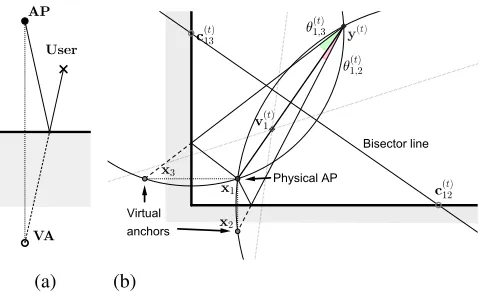
elementsxiare spanned by the index setI. The setX ={xi} will be referred to as{xi}when there is no ambiguity.k · kF denotes the Frobenius norm, andEindicates the expectation. We will denote the set of physical anchor APs asAp and the set of virtual anchors (VAs, defined as the reflection of a physical APa∈ Ap through a reflective surface, see Fig. 1a) asAv, so that A=Ap∪ Av is the set of all anchors. Callxi the location of theith anchor, andytthe location of the user at time epocht. The setVcontains all pairs(i, t)such that at time
tthe user can measure the AoA of a visible path corresponding to anchori, denoted as φ(t)i . The ADoA corresponding to the signals from anchorsi, j∈ Aat timet is indicated asθ(t)ij = φj(t)−φ(t)i , andζij(t)=π/2−θ(t)ij (angles are measured in the counterclockwise direction). Finally,
Rα=
cosα −sinα sinα cosα
(1)
rotates a vector counterclockwise by an angleαinR2.
B. Geometry of the ADoA localization process
For the moment, assume that the AoAs are known without error. This assumption will be relaxed later. The ADoA localization problem consists in finding a set of anchor and user locations over time, such that the pair-wise differences among the AoAs of the anchor signals are compatible with the pair-wise differences among the AoA spectrum components detected by the user. Assuming the user is receiving a signal from anchors i and j at time t, with angles φ(t)i and φ(t)j , respectively, the constraint above means that the user is located on an arc of circumference that stands upon segmentxixj.
When a third anchor k is available, the intersection of the two arcs standing upon chordsxixj and, e.g.,xjxk provides an estimate for the location of the node. An example of ADoA geometry is provided in Fig. 1b. Lettbe the current time and
y(t)be the position of the node. From this position and at this time, the node sees three anchors, of which one is a physical AP (located at x1), whereas the others are VAs obtained by mirroring the AP at x1 with respect to the bottom and left walls, represented by a thicker black line. The two VAs are respectively located atx2 andx3.
C. Formalization
(a) (b)
Fig. 1. Virtual anchor corresponding to the reflection of the signal from a physical AP (a) and geometry of the ADoA localization process (b).
arc that contains anchors i and j, respectively located at xi and xj. The formula for c(t)i,j can be found, e.g., in [14]. By construction, the center of every arc stands on the line that bi-sects the segmentxiy(t). Fig. 1 shows an example of this with two circumferences of centers c(t)12 andc(t)13, both containing anchor 1 atx1. By definingv(t)i = 2y(t)−xi
−2
(y(t)−x i), the equation of the bisector line is:
v(t)i T(c(t)ij −xi) = 1, (2)
whereT indicates transposition. Using the formula of the arc center, we have that
c(t)ij =
Rζ(t) ij
2 sinθij(t)
(xj−xi) +xi, (3)
and substituting (3) into (2) yields
v(t)i TRζ(t) ij
(xj−xi) = 2 sinθ (t)
ij . (4)
Since the centers of all arcs that contain anchoriat timetlie on the line defined by (2), we observe that they also intersect in a single point, which by construction is symmetric to anchori
with respect to the bisector line in (2). This point is an estimate for the user’s location. Therefore, solving (4) for v(t)i yields the location of the user at timet.
We now relax the assumption of perfect channel knowledge. As AoA estimates are affected by errors, the system of equations in (4) may become infeasible. The approximate solution that minimizes the quadratic error with respect to the true solution is given by the problem
arg min {v(it)},{xi}
X
(i,t),(j,t)∈V
v(t)i TRζ(t) ij
(xj−xi)−2 sinθ (t) ij
2 , (5)
where the sum is computed over all i, j, and t such that
(i, t),(j, t)∈ V. We remark that the solution to this problem depends on the location of the anchor nodesxi,i∈ A, which is also unknown. In the following section we detail an efficient algorithm to estimate {v(t)i },(i, t)∈ V and{xi}i∈A.
IV. ALGORITHM
The objective function in (5) is an order-4 polynomial in a multi-dimensional space. To tackle the minimization of the objective function efficiently, we proceed by successive refine-ments. The basic idea of the algorithm is to overdetermine the system of equations resulting from (5), and to iteratively solve two MMSE problems over{vi(t)},(i, t)∈ V and{xi}i∈Afor
up to MaxIT iterations. This makes the optimization faster, as the search space at each step is limited. To the best of our knowledge, this is the first time that the ADoA localization problem is tackled using this method. For the moment, assume that an initial estimate of the anchors’ locations is available. Sections IV-A and IV-B develop the steps of the algorithm. Building on the corresponding derivation, Section IV-C finally presents how the initial anchor location estimate is obtained.
A. Optimization over{v(t)i }
Call J(t) = {j ∈ As.t. (j, t) ∈ V} the set of valid values for the anchor index j at time t. Because the pairs
(i, t),(j, t) ∈ V contribute independently to (5), the solution to the minimization problem when the values ofxi are given can be computed for each pair(i, t)∈ V as
b
v(it)= arg min
vi(t) X
j∈J(t)
v(it)TR
ζ(ijt)(xj−xi)−2 sinθ
(t)
ij 2
. (6)
DefineM(t)i as the2× |J(t)|matrix whose columns are
[M(t)i ]:,k=Rζ(t) ik
(xj−xi), (7)
where 1 ≤ k ≤ |J(t)|, j is the kth element of J(t), and the colon notation[·]:,k conveys that we refer to all elements of column k. Finally, call b(t)i ∈ R1×|J | the column vector
whosekth entry equals[b(t)i ]k = 2 sinθ (t)
ik, fork∈ J
(t). This
makes it possible to rewrite (6) as
b
v(t)i = arg min v(it)
kvi(t)TM(t)i −b(t)i k2, (8)
so that the MMSE optimization problem in (8) is solved as
vi(t)= (M(t)i M(t)i T)−1M(t)i b(t)i T. (9)
B. Optimization over{xi}
After computing (9), we proceed to minimize the objective function over the locations of the anchors visible at time t,
{xi}s.t.(i, t)∈ V, by assuming that the termsv (t)
i are given. Define the anchor location vector as
x=hxT1xT2 · · · xT|A|i
T
. (10)
Since the expressionvi(t)TRζ(t) ij
(xj−xi)is linear∀i, j, ts.t.
(i, t),(j, t)∈ V, and the values ofv(t)i are given, the objective function in (5) can be rearranged to yield the problem:
b
x= arg min x
X
(i,t),(j,t)∈V
q(t)ij Tx−2 sinθ(t)ij
2
where the column vector q(t)ij groups the coefficients that multiply each component of the respectivexi,xj ∈ Ain (5). By vertically concatenating the termsq(t)ijTinto matrixQand
the terms2 sinθij(t)into matrixb, (11) can be expressed as:
b
x= arg min x
kQx−bk2, (12)
which is again an MMSE problem with solution
b
x= (QTQ)−1QTb. (13)
By iterating the computation steps described in this subsec-tion and Secsubsec-tion IV-A, the locasubsec-tion estimates for the user and the anchors (both physical and virtual) converge to a solution. The following subsection explains how to obtain good initial estimates of the anchor locations to start the optimization of the objective function.
C. Initial estimation of the anchor locations
To enable the first computation of (13), we re-arrange (5) so that it becomes amenable to a grid search procedure. First, note that the objective function to optimize in order to obtain an estimate of{xi}can be derived from (5) when eachv
(t) i is defined by (9), and in turnM(t)i is defined by the relationship in (7), which depends on {xi}. An initial estimate for {xi}, can therefore be obtained as
{xbi}= arg min
{xi} X
(i,t)∈V min
vi(t)
v
(t)T
i M
(t) i −b
(t) i 2 . (14)
Note that each term minv(t) i v (t)T i M (t) i − b
(t) i 2 is the
distance between the vector b(t)i and the space generated by the two rows of M(t)i . By calling w(t)i T = [M(t)i ]1,: and z(t)i T = [M(t)i ]2,: the first and second row of M
(t) i , respectively, and by using the formula for the distance between a plane and a point, we can rewrite (14) as
{xbi}= arg min
{xi} X (i,t)∈V b (t) i 2 −
Πw(t) i ,z
(t)
i
(b(t)i )
2
, (15)
whereΠw(t) i ,z
(t)
i
(b(t)i )is the projection ofb(t)i onto the plane
generated by w(t)i and z(t)i . The problem in (15) is then equivalent to
{bxi}= arg max
{xi} X
(i,t)∈V
Πw(t)
i ,z
(t)
i
(b(t)i )
2
, (16)
and by applying the projection modulus formula, we get the final expression
{bxi}= arg max
{xi} X
(i,t)∈V
(wi(t)Tb(t)i )2kz(t) i k
2
kwi(t)k2kz(t)
i k2−(w (t)T i z
(t) i )2
(17)
+(z
(t)T i b
(t) i )
2kw(t) i k
2−2(w(t)T i b
(t) i )(z
(t)T i b
(t) i )(w
(t)T i z
(t) i )
kw(t)i k2kz(t)
i k2−(w (t)T i z
(t) i )2
.
We remark that the summation terms in (17) can be evaluated only if wi(t) and z(t)i are linearly independent. If, however, they lie on the same line, (17) can be evaluated as in (16).
Recall from the discussion at the beginning of Section III that the solution to problem (5) is invariant to rotation, scaling and translation. To remove this ambiguity and allow the user to at least localize itself with respect to the anchors encountered over time, we choose to arbitrarily fix the location of two access points (with no loss of generality,x1 andx2), and set
x1 = [0,0]T,x2 = [1,0]T. We then perform a grid search to solve (17) forx3,x4, by limiting the search space to the first four known anchors. This limits the grid search complexity while allowing to initialize the algorithm with a sufficient number of anchors (provided that at least four of them are visible). We then proceed by obtaining a first estimate of the location of every other known anchor, one anchor at a time. To do so, we solve (17) by grid search overxn by limiting the scope of the search only to the firstnanchors,5≤n≤ |A¯(t)|, where |A¯(t)| is the set of anchors known at time t. This sequential optimization also aims at reducing the grid search complexity while achieving a suboptimal but sufficiently good initial solution. From this point, the optimization over{xi}can be carried out as outlined in Section IV-B.
D. Algorithm summary
The pseudo-code of the JADE algorithm is provided in Algorithm 1. We start by arbitrarily fixing the location of x1 andx2(line 2) and by solving (17) via grid search to obtain an initial estimate of the anchors’ locations, by first limiting the search toi≤4(line 6) and then by estimating one additional anchor at each step (line 8). We now iteratively minimize (5) first over the variables v(t)i (line 10, see Section IV-A) and then over the anchor locations{xi}(line 11, see Section IV-B). After finding the solution we invert the definition ofv(t)i in (4) to find the expression of y(t) = x
i + 2 v (t) i /kv
(t) i k2 and average them over the set of possible values ofi(line 12). The steps above are repeated for every3≤t≤T. The complexity of JADE isO(|A|2G), whereG= 216 is the number of grid search points for each anchor inA. Each optimization step of lines 10 and 11 has complexityO(T|A|2MaxIT). Because the grid search is run only once andMaxIT≤100 steps suffice
Algorithm 1: The JADE algorithm
1 Function JADE(V, φ(t)i ∀(i, t)∈ V, T,MaxIT)
Require: At least 4 anchors encountered;T ≥3
2 Setx1= [0,0]T,x2= [1,0]T 3 whilet≤T do
4 A¯(t)←Set of anchors encountered untilt
5 Indexxn∈A¯(t)byn∈ {1,2,· · · ,|A¯(t)|}
6 Find x3,x4 by grid search over (17) fori≤4
7 forn←5 to|A¯(t)| do
8 Find xn by grid search over (17) fori≤n
9 fork←1 to MaxITdo
10 Compute{v(t)i }(i,t)∈V using (9)
11 Compute{xi} using (13)
for JADE to converge, the resulting complexity is suitable even for resource-constrained mobile devices. For largeT, the complexity can be reduced via a sliding window approach.
We remark that in order to obtain a unique solution for both the location of the user and the position of the anchors, JADE needs at least four anchors to be known to the user, and at least three measurements to be taken at different locations over time. This includes virtual anchors, i.e., one physical AP and three reflections would already suffice. This differs from the classical ADoA algorithm [14], where the location of the anchors is known, and three anchors suffice to compute a unique solution in the absence of AoA estimation errors. We emphasize that JADE can bootstrap with as little as a single physical AP (provided that there are at least three additional VAs); that it can automatically estimate the environment and, once a reasonably accurate map is available, can act as a proxy to facilitate AP association without a full beam training procedure. It can also predict when APs would disappear behind obstacles as the user moves, to anticipate required handovers, or steer the antenna beam to an alternative reflected path purely based on the known reflective walls. In addition, each new measurement allows the user to refine the location estimates computed in the past and improve the knowledge of the environment over time.
E. Simultaneous localization and mapping (SLAM)
Once a sufficiently accurate estimate of the anchors’ and user’s locations is available, the geometric relationship be-tween physical APs and their corresponding VAs can be leveraged to reconstruct the shape of reflective surfaces and walls. Call P(xi) the “parent” of VA xi, i.e., the physical AP that generates xi by reflection. As shown in Fig. 1, if at time t the user is at location y(t) and VA x
i is visible (i.e.,
(i, t) ∈ V), then the point on the wall where the signal of the physical AP P(xi) reflects is located at the intersection between segment y(t)x
i and the bisector line of segment
xiP(xi). Computing this intersection can lead to spurious solutions if the estimate of xi or P(xi) is not sufficiently accurate. To avoid this, we define a reliability measure for the computed intersection points. This reliability takes into account different user locations, so that the reflection point on the wall is seen under different angles, and is higher if the user is close to the reflection point, since this reduces the probability of computing spurious solutions. Define the partial reliability of anchor xi along directionw ∈R2, kwk= 1as
wTSiw, whereSi is a symmetric matrix.
For everyi, tsuch that(i, t)∈ V, we set the contribution to
Si at timetto be a (t)T i a
(t) i /ka
(t) i k
4 fora(t)
i =xi−y(t). This contribution has the advantage of being maximum along the directiona(t)i /ka(t)i k, to be identically 0 along the direction or-thogonal to it, and to decrease as the length ofxiy(t)increases.
Si is finally computed as Si=Pt:(i,t)∈Va
(t)T i a
(t) i /ka
(t) i k
4.
We define the reliability of anchor xi, r(xi), as the min-imum of the partial reliability of anchor xi over the set of directions w∈R2:kwk= 1, which by the symmetry of Si is equivalent to the minimum over the set of its eigenvalues,
i.e., r(xi) = minkλk, whereλk is thekth eigenvalue ofSi. Having computed the reliability of all anchors, we estimate the wall location only for each pair(i, t)∈ V such thatr(xi) andr P(xi)
are both larger than 0.01, wherexiis a VA and
P(xi) is its parent physical AP.
V. SIMULATION RESULTS
We now evaluate the performance of JADE in terms of localization error. We also implement two practical localiza-tion schemes, triangulalocaliza-tion-plus-validalocaliza-tion (TV) and a baseline version of ADoA [14], and compare their localization accuracy against that of JADE. The TV algorithm triangulates the position of a user by associating the two strongest AoA spectrum components to the known physical APs and VAs, and validates the position via further triangulations involving other anchors. TV needs additional knowledge about the absolute orientation of the user with respect to the chosen coordinate system. The ADoA approach is similar to the scheme outlined in Section III-B. By associating the known VAs to the detected signal AoAs, it identifies a feasible set of user locations, and returns the median of this set as the final estimate.
Unlike JADE, TV and ADoA work under the assumption that the floor plan, the obstacles in the room, and the location of the physical APs are known to the user, hence the loca-tion of all VAs generated by mirroring the physical AP off reflective surfaces are also perfectly known. TV and ADoA always localize the node independent of past measurements. In contrast, JADE can fuse information related to different AoA spectrum estimates taken by the user over time, and thus its error decreases as more estimates become available.
To evaluate the performance of the schemes, we design a number of scenarios with different degrees of complexity, including different reflective and absorbing surfaces. We as-sume that a user moves throughout each scenario and takes AoA measurements at fixed time intervals t = 1,2,· · ·, T, each from a different location. To derive realistic estimation errors, we synthesize beam shapes for a uniform linear antenna array with 8, 16 and 32 elements. Under typical signal-to-noise ratio conditions, these correspond to zero-mean Gaussian-distributed error of standard deviation σ ∈ {5◦,2◦,1◦}, respectively. We recall that different APs and VAs become visible to the user as it moves.
A. Performance of JADE vs. TV and ADoA
mean squared error sense. This step is purely done to compute the absolute localization error for each of the T measurement epochs. We collect the statistics of this error for JADE, TV and ADoA over a Monte-Carlo set of Ntr simulations, where random errors on AoA estimates are re-drawn at each run. This yields a total of NtrT error measurements for each scheme.
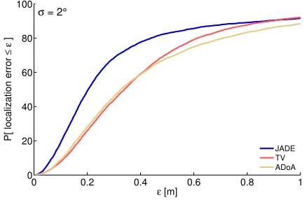
Fig. 3 depicts the cumulative distribution function (CDF) of the localization error for all schemes in the presence of 3 (dotted) and 4 APs (solid). The left panel refers to the case
σ = 1◦, the center panel to σ = 2◦ and the right panel to σ = 5◦. We observe that JADE consistently outperforms TV and ADoA, which is remarkable given that JADE starts with no knowledge of the APs and of the room map. Only for very low angle error does the TV scheme marginally outperform JADE, due to the fact that it has perfect knowledge of the environment. For all schemes, increasing the number of physical APs from 3 to 4 improves the accuracy of the localization process, especially for ADoA, which requires one more anchor than TV to work well. The probability of achieving sub-meter accuracy is between 0.85 and 0.95 for σ = 1◦. As σ increases, the accuracy of all schemes deteriorates. However, JADE is considerably more robust than TV and ADoA, especially with 4 APs. Despite a lower initial slope of the CDF for increasingσ, it still achieves a probability of sub-meter accuracy ≈0.95 in all cases, and its sub-50 cm accuracy in the worst case (σ= 5◦) is about 66% with 3 APs and 85% with 4 APs, much higher than TV and ADoA. This precision would be sufficient to support indoor navigation even in the presence of large AoA estimation errors.
B. Mobile path reconstruction
We proceed by evaluating the accuracy of JADE, TV and ADoA in the reconstruction of the trajectory of a mobile user. We first consider the same scenario of Fig. 2 with 4 APs. Fig. 4a shows the true trajectory of the node and the locations where the node performs AoA training compared to JADE’s estimates of the user locations and of the AP positions. Note that the VAs are hidden for clarity but are indeed used by all schemes. We observe that JADE achieves a very accurate reconstruction of the user’s trajectory and AP locations, and those not perfectly aligned are within centimeters of the ground truth. Despite TV and ADoA knowing the room and obstacles as well as the AP locations, their estimates are much less accurate. This can be observed both from Fig. 4b, where
−5 0 5 10 15
−5 0 5 10
x−axis location [m]
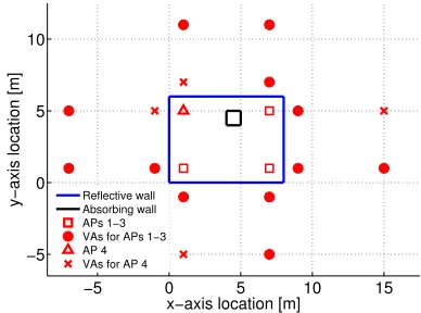
y−axis location [m] Reflective wallAbsorbing wall APs 1−3 VAs for APs 1−3 AP 4 VAs for AP 4
Fig. 2. Simple room geometry for the evaluation of the JADE, TV and ADoA schemes, including reflective boundary walls and an absorbing obstacle. The location of 4 physical APs and all their related VAs are shown.
several outliers appear along the user trajectory, and from Fig. 4c, which shows the CDF of the localization error in this scenario. These results confirm that JADE consistently outperforms the other two schemes.
We now consider a larger scenario composed of offices on the top side, and an open space at the bottom where we assume several computers to be located, whose monitors act as reflective surfaces for the AP signals. A couple of walls further divide the space on the right side of the room. We assume that one AP is deployed in each office, three are located in the right section of the room, and two more near each group of 3 monitors in the bottom-left section. In this case, the user starts from the right side, walks through the open space and stops in the top-left office (see 5a) The unknown obstacles and the rich set of reflective surfaces in the room pose a significant challenge to JADE, especially due to the continuous appearance and vanishing of connections to different APs, which makes the estimation of the location of physical and virtual anchors comparatively less accurate than in the previous scenarios. Still, the broad majority of the user positions and AP locations are estimated very accurately. The worst cases almost always provide sub-meter accuracy (as seen from the CDF curves in Fig. 6). We remark that in such a complex scenario, the full knowledge of the floor plan and obstacles available to TV and ADoA yields a considerable advantage, as confirmed by the fact that the localization error CDF curves of TV and ADoA are much closer to that of JADE than in the previous case. The probability of achieving
sub-0 0.2 0.4 0.6 0.8 1
0 20 40 60 80 100
ε [m]
P[ localization error
≤
ε
]
JADE TV ADoA
3 APs 4 APs
σ = 1°
0 0.2 0.4 0.6 0.8 1
0 20 40 60 80 100
ε [m]
P[ localization error
≤
ε
]
JADE TV ADoA
3 APs 4 APs
σ = 2°
0 0.2 0.4 0.6 0.8 1
0 20 40 60 80 100
ε [m]
P[ localization error
≤
ε
]
JADE TV ADoA
3 APs 4 APs
σ = 5°
0 2 4 6 8 −1
0 1 2 3 4 5 6 7
x−axis location [m]
y−axis location [m]
(a) JADE.
0 2 4 6 8
−1 0 1 2 3 4 5 6 7
x−axis location [m]
y−axis location [m]
(b) TV and ADoA.
0 0.2 0.4 0.6 0.8 1
0 20 40 60 80 100
ε [m]
P[ localization error
≤
ε
]
JADE TV ADoA σ = 2°
(c) Localization error CDF.
Fig. 4. Path reconstruction in the scenario of Fig. 2 with 4 APs. The right panel shows the CDF of the localization error for all schemes.σ= 2◦.
0 4 8 12 16
0 2 4 6 8 10 12
x−axis location [m]
y−axis location [m]
(a)T= 60.
0 4 8 12 16
0 2 4 6 8 10 12
x−axis location [m]
y−axis location [m]
(b)T = 120.
0 4 8 12 16
0 2 4 6 8 10 12
x−axis location [m]
y−axis location [m]
(c)T = 180.
Fig. 5. SLAM and path reconstruction in the office scenario for different values ofT.
meter accuracy is also comparable for the three schemes. This further confirms the merit of JADE’s design, which performs at least comparable to and often much better than schemes that do require full environment information.
C. SLAM and estimation accuracy over time
We now test the room boundary and obstacle estimation capabilities of JADE as explained in Section IV-E. We do this by considering a progressively longer path that unfolds through the space of the office scenario described above, and visits more and more sections of the area, each time adding measurements to the knowledge available to the user. This makes it possible to refine the location estimates for both the anchors and user, and thereby allow reliable room boundary and obstacle estimates to be computed. Fig. 5 depicts the SLAM process in three subsequent steps: for the firstT = 60
measurement epochs (Fig. 5a), for T = 120 over a longer path (Fig. 5b) and for T = 180 over a complete path that visits most of the relevant spaces in the office area (Fig. 5c). AfterT = 60, the anchor locations and the user trajectory have been estimated with a high degree of accuracy. The visited spaces and the encountered AP↔VA pairs allow JADE to already estimate the position of some walls. These are represented as black crosses in Fig. 5. We notice that both the walls and some of the screens in the open space section are estimated with very good accuracy. Increasing the path length and the number of measurements epochs to T = 120
allows more pairs to be discovered and exploited to estimate
0 0.2 0.4 0.6 0.8 1 0
20 40 60 80 100
ε [m]
P[ localization error
≤
ε
]
JADE TV ADoA
σ = 2°
Fig. 6. CDF of the localization error for JADE, TV and ADOA in the office scenario of Fig. 5.
20 40 60 80 100 120 Measurement epoch t
0 2 4
Error [m]
Median 25th-75th percentile 10th-90th percentile
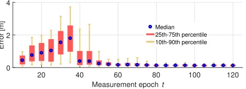
Fig. 7. Evolution of the statistical dispersion of the localization error over time in the office scenario as JADE is fed with additional measurements.
remarkably good, given that the process does not leverage any radar-like mapping approach.
We conclude our evaluation with Fig. 7, showing how the statistical dispersion of the user localization error varies as additional measurements are provided to JADE along the path of Fig. 5c. At t = 10, the system has barely bootstrapped, and the user has visited a limited portion of the path, mostly limited to the center-right section of the area. This keeps the localization error low. As the user moves to the bottom-left open-space area, which is very complex and for which no information is initially available, JADE’s error increases up to
t = 35. Once sufficient information is acquired (t = 40), the median localization error falls below 50 cm, and its dispersion decreases again. After 90 measurement epochs, the 90th percentile of the localization error is less than 40 cm and does not increase over time any more.
VI. CONCLUSIONS
In this paper we proposed JADE, an algorithm that jointly localizes a mobile user in an indoor space, estimates the position of the deployed access points, and opportunistically derives a map of the indoor area. The algorithm is tailored to mmWave equipment, and specifically hinges on the capability to estimate AoA information for different access points via the beam training procedure carried out by equipment compliant with the IEEE 802.11ad standard. Notably, JADE does not require any a-priori knowledge about the environment, neither about the floor plan of the indoor area, the position of reflective or absorbing surfaces therein, nor about the location and number of access points. An extensive set of simulation results demonstrates that JADE achieves remarkably good performance, and sub-meter user localization accuracy in more than 90% of the cases, even for highly erroneous AoA estimates. In addition, it almost always outperforms other algorithms that, instead, do require full information about the environment and have no SLAM capabilities. Future work along this line includes the experimental validation of JADE using measurements with real mmWave devices.
ACKNOWLEDGMENT
This work has been supported in part by the ERC project SEARCHLIGHT, grant no. 617721, the Ramon y Cajal grant RYC-2012-10788, the grant TEC2014-55713-R (Hyperadapt) and the Madrid Regional Government through the TIGRE5-CM program (S2013/ICE-2919).
REFERENCES
[1] K. Witrisal et al., “High-accuracy localization for assisted living: 5G systems will turn multipath channels from foe to friend,”IEEE Signal Process. Mag., vol. 33, no. 2, pp. 59–70, Mar. 2016.
[2] L. Barkhuus and A. K. Dey, “Location-based services for mobile telephony: a study of users’ privacy concerns,” inProc. IFIP Interact, Zurich, Switzerland, Sep. 2003.
[3] T. Nitscheet al., “Steering with eyes closed: mm-wave beam steering without in-band measurement,” inProc. IEEE INFOCOM, Hong Kong, China, Apr. 2015.
[4] D. Lymberopoulos et al., “A realistic evaluation and comparison of indoor location technologies: Experiences and lessons learned,” in Proc. IPSN, Seattle, WA, Apr. 2015.
[5] J. Xiong and K. Jamieson, “Arraytrack: A fine-grained indoor location system,” inProc. USENIX, Lombard, IL, Apr. 2013.
[6] E. Perahiaet al., “IEEE 802.11ad: Defining the next generation multi-Gbps Wi-Fi,” inProc. IEEE CCNC, Las Vegas, NV, Jan. 2010. [7] N. Peinecke, H. Doehler, and B. Korn, “Phong-like lighting for MMW
radar simulation,” inProc. SPIE, Cardiff, UK, 2008.
[8] A. Maltsev et al., “Experimental investigations of 60 GHz WLAN systems in office environment,” IEEE J. Sel. Areas Commun., vol. 27, no. 8, pp. 1488–1499, Oct. 2009.
[9] A. Alkhateeb et al., “Channel estimation and hybrid precoding for millimeter wave cellular systems,”IEEE J. Sel. Topics Signal Process., vol. 8, no. 5, pp. 831–846, Oct. 2014.
[10] H. Liu et al., “Survey of wireless indoor positioning techniques and systems,”IEEE Trans. Syst., Man, Cybern. C, vol. 37, no. 6, pp. 1067– 1080, Nov. 2007.
[11] T. Rappaportet al., “Millimeter wave mobile communications for 5G cellular: It will work!”IEEE Access, vol. 1, pp. 335–349, 2013. [12] F. Guidi, A. Guerra, and D. Dardari, “Millimeter-wave massive arrays
for indoor SLAM,” inProc. IEEE ICC, Sydney, Australia, Jun. 2014. [13] H. Chuet al., “Joint design of axis alignment and positioning for NLoS
indoor mmWave WLANs/WPANs,” in Proc. IEEE VTC, Vancouver,
Canada, Sep. 2014.
[14] A. Olivieret al., “Lightweight indoor localization for 60-GHz millimeter wave systems,” inProc. IEEE SECON, London, UK, Jun. 2016. [15] H. Durrant-Whyte and T. Bailey, “Simultaneous localization and
map-ping: part I,”IEEE Robot. Autom. Mag., vol. 13, no. 2, pp. 99–110, Jun. 2006.
[16] T. Dumont and S. Le Corff, “Simultaneous localization and mapping in wireless sensor networks,”Elsevier Signal Processing, vol. 101, pp. 192–203, Aug. 2014.
[17] P. Meissner, C. Steiner, and K. Witrisal, “UWB positioning with virtual anchors and floor plan information,” inProc. WPNC, Mar. 2010. [18] C. Zhang et al., “iLocScan: Harnessing multipath for simultaneous
indoor source localization and space scanning,” inProc. ACM SenSys, Memphis, TN, Nov. 2014.
[19] Sen Souvik et al., “Avoiding multipath to revive inbuilding WiFi localization,” inProc. MobiSys, Taipei, Taiwan, Jun. 2013.
[20] Alex Mariakakiset al., “SAIL: Single access point-based indoor local-ization,” inProc. MobiSys, Jun. 2014.
[21] P. Meissneret al., “Accurate and robust indoor localization systems using ultra-wideband signals,” inProc. ENC, Vienna, Austria, Apr. 2012. [22] K. Kaemarungsi and P. Krishnamurthy, “Modeling of indoor positioning
systems based on location fingerprinting,” in Proc. IEEE INFOCOM, Hong Kong, China, Mar. 2004.
[23] M. D. Abouzahra and R. K. Avent, “The 100-kW millimeter-wave radar at the Kwajalein Atoll,” IEEE Antennas Propag. Mag., vol. 36, no. 2, pp. 7–19, Apr. 1994.
[24] H. Deng and A. Sayeed, “Mm-wave MIMO channel modeling and user localization using sparse beamspace signatures,” inProc. IEEE SPAWC, Toronto, Canada, Jun. 2014.
[25] A. Guerra et al., “Application of transmitarray antennas for indoor mapping at millimeter-waves,” inProc. EuCNC, June 2015.
[26] A. Shahmansooriet al., “5G position and orientation estimation through millimeter wave MIMO,” inProc. IEEE GlobeCom, Dec. 2015. [27] H. El-Sayed, G. Athanasiou, and C. Fischione, “Evaluation of
local-ization methods in millimeter-wave wireless systems,” in Proc. IEEE CAMAD, Athens, Greece, Dec. 2014.