https://doi.org/10.5194/se-8-1161-2017
© Author(s) 2017. This work is distributed under the Creative Commons Attribution 4.0 License.
Extension parallel to the rift zone during segmented fault growth:
application to the evolution of the NE Atlantic
Alodie Bubeck1, Richard J. Walker1, Jonathan Imber2, Robert E. Holdsworth2, Christopher J. MacLeod3, and David A. Holwell1
1Department of Geology, University of Leicester, Leicester, LE1 7RH, UK 2Department of Earth Sciences, Durham University, Durham, DH1 3LE, UK
3Department of Earth and Ocean Sciences, Cardiff University, Cardiff, CF10 3AT, UK
Correspondence to:Alodie Bubeck ([email protected])
Received: 21 August 2017 – Discussion started: 24 August 2017
Revised: 15 October 2017 – Accepted: 17 October 2017 – Published: 22 November 2017
Abstract.The mechanical interaction of propagating normal faults is known to influence the linkage geometry of first-order faults, and the development of second-first-order faults and fractures, which transfer displacement within relay zones. Here we use natural examples of growth faults from two ac-tive volcanic rift zones (Koa‘e, island of Hawai‘i, and Krafla, northern Iceland) to illustrate the importance of horizontal-plane extension (heave) gradients, and associated vertical axis rotations, in evolving continental rift systems. Second-order extension and extensional-shear faults within the relay zones variably resolve components of regional extension, and components of extension and/or shortening parallel to the rift zone, to accommodate the inherently three-dimensional (3-D) strains associated with relay zone development and rota-tion. Such a configuration involves volume increase, which is accommodated at the surface by open fractures; in the sub-surface this may be accommodated by veins or dikes oriented obliquely and normal to the rift axis. To consider the scalabil-ity of the effects of relay zone rotations, we compare the ge-ometry and kinematics of fault and fracture sets in the Koa‘e and Krafla rift zones with data from exhumed contemporane-ous fault and dike systems developed within a > 5×10⁴km2 relay system that developed during formation of the NE At-lantic margins. Based on the findings presented here we pro-pose a new conceptual model for the evolution of segmented continental rift basins on the NE Atlantic margins.
1 Introduction
The primary regional-scale segmentation of extensional ter-ranes is controlled by the development of networks of normal fault systems and the partitioning of strain across them. Nor-mal faults comprise multiple discontinuous, non-collinear segments, with overlaps and segment linkage forming char-acteristic stepping geometries on a broad range of scales (e.g. Cartwright et al., 1996; Peacock et al., 2000; Acocella et al., 2005; Long and Imber, 2011; Henstra et al., 2015). Fault growth models have been derived using natural examples and numerical, or scaled-analogue modelling techniques, in which normal faults grow through stages in which discon-tinuous segments interact and link across relay zones to form composite structures with fault displacement deficits initially accommodated by soft-linkage rotation and/or material fold-ing (e.g. Trudgill and Cartwright, 1994; Gupta and Scholz, 2000; Peacock, 2002; Long and Imber, 2010).
been well established (e.g. Peacock and Sanderson, 1991; Peacock, 2002; Fossen and Rotevatn, 2016). Normal fault displacement is typically considered with emphasis on the vertical motion (fault throw), which can be measured using offset bedding, either in the field, laboratory, or using high-resolution seismic imaging. In horizontally layered materi-als, displacement (throw) gradients on adjacent normal faults are commonly accommodated by relay structures (e.g. Pea-cock and Sanderson, 1991; Childs et al., 1995; Long and Imber, 2010), requiring horizontal axis bending of the host layering (Fig. 1). The bounding faults of a relay zone also exhibit opposing horizontal displacement (heave) gradients, which requires a component of vertical axis rotation to main-tain the connection between the hanging wall and footwall (e.g. Ferrill and Morris, 2001). Few studies have addressed this rotational strain (see e.g. Koehn et al., 2008) and the resulting horizontal extension profile between faults or the potential for non-plane stresses and strains within the relay zone. Unlike horizontal axis rotation, it cannot be accommo-dated by layer-parallel or flexural slip between layers (unless layering is vertical) and thus requires the material to bend or stretch within the layer plane.
We present field examples of growth faults from two active volcanic rift zone segments – the Koa‘e (island of Hawai‘i) and Krafla (northern Iceland) fault systems – to demon-strate the inherently three-dimensional (3-D) strains associ-ated with extensional strain gradients within evolving relay zones. The Koa‘e fault system represents an early stage rift that connects the East and Southwest rift zones of K¯ılauea Volcano to produce a continuous zone of extension that fa-cilitates southward flank motion. The Krafla fissure swarm represents a well-established and highly extended portion of the Neovolcanic Zone of Iceland: a subaerially exposed seg-ment of the NE Atlantic spreading ridge. Faults in both study areas are interpreted to be upward-propagating (e.g. Tentler, 2005; Martel and Langley, 2006) syn-volcanic growth faults (e.g. Macdonald et al., 1996; Dauteuil et al., 2001; Holland et al., 2006). The two case studies represent early and advanced stages in normal fault linkage during rifting.
In both case studies the expression of surface strains records minor (≤20 %) extension, in which respect they can be considered analogous to the surface expression of evolv-ing extensional systems. The aim of this paper is to demon-strate the importance of displacement variation as a function of fault heave, rather than throw, and highlight the potential for the development of non-plane strains and volume change on the scale of the intervening relay zones. We consider the potential for such 3-D strains to form a viable alternative model to explain complex fault sets in laterally propagat-ing rift systems: here we contrast structures in the Koa‘e and Krafla regions to upper crustal (e.g.∼1–6 km depth) struc-tures of a scale that is at least 1 order of magnitude greater, developed along the NE Atlantic margins. For comparison, new and existing kinematic and geometric data are presented for Kangerlussuaq (east Greenland) and the Faroe Islands
(European) portions of the NE Atlantic margins. Based on these examples, we suggest a new conceptual model for the evolution of segmented continental rift basins, with specific reference to the NE Atlantic margin.
2 Background: displacement transfer and relay zones in segmented normal fault systems
Two-dimensional analyses of the stresses surrounding en échelon faults and dikes have demonstrated that mechani-cal interaction of opposing elastic stress fields produce ar-eas of highly perturbed stress, which exert a control on the growth, slip distribution, and geometry of faults (e.g. Segall and Pollard, 1980; Sempere and Macdonald, 1986; Cowie and Scholz, 1992; Crider and Pollard, 1998). To maintain the extensional strain across the fault system as a whole (i.e. rep-resenting a fully linked, mature system), the volume ahead of the fault tips is required to accommodate the opposing along-strike displacement gradients on the first-order bound-ing fault structures. This may be accommodated in this inter-fault region, or relay zone, through components of elastic and inelastic strain (e.g. Peacock and Sanderson, 1991, 1994; Childs et al., 1995; Long and Imber, 2010), and depending on the degree of overlap and separation of individual segments, may lead to different styles of deformation (e.g. Tentler and Acocella, 2010; Long and Imber, 2011; Childs et al., 2017) (Fig. 1a, b).
Using scaled-analogue models, Tentler and Acocella (2010) showed that a large underlap (relative to fracture length) between fracture segments produces elongated relay zones with new linking fractures opening ahead of the tips, striking subparallel to the bounding fractures (Fig. 1d(i)). De-creasing the underlap of the bounding fractures (Fig. 1d(ii– iv)) results in the growth of open fractures in the relay zones that strike at increasingly higher angles to the main struc-tures. The propagation of these high-angle fractures gener-ates a local component of extension, and volume increase, in a direction parallel or at low angles to the strike of the bound-ing fractures. At the same time, the component of extension orthogonal to the bounding structures decreases. At larger overlap geometries (Fig. 1d(v)), linking fractures strike at a lower angle, resulting in a reduction of the local component of bounding fracture-parallel extension and an increase in the fracture-normal component. The model configurations of Tentler and Acocella (2010) represent single stages of prop-agation and linkage, rather than the full progression. In na-ture, however, the process should graduate through some or all of these stages, as the bounding structures propagate to-ward each other and link, subjecting the relay zone to distor-tions as a function of the changing fault cut-off line lengths associated with slip accumulation (Fig. 1c, d).
Vertical axis rotation
Horizontal axis rotation
Zero overlap
Negative overlap Positive overlap
Fault A Fault B
X
X’
(c)
Overlap
separation Fault A
Fault A
Fault B
Distance
Fault B
Th
ro
w
X X’
X X’
(b) (a)
(e) Le
(d)
ft-stepping: clockwise vertical axis rotationRight-stepping: anticlockwise vertical axis rotation
Distance Distance Distance Distance Distance
Ex
tension (he
av
e)
Fracture-normal ext.
i ii iii iv v
Fracture-parallel ext.
Figure 1. (a)Schematic diagram illustrating a relay zone between two normal faults (after Ferrill and Morris, 2001) showing the location of the footwall (FW) and hanging wall (HW) cut-off lines.(b)Map view of the block model in(a)showing fault overlap and separation.(c)
Distance versus displacement (throw) profile for transect X-X’.(d)(i–v) Second-order fault geometries as a function of fault overlap (redrawn from Tentler and Acocella, 2010) with local and regional extension directions indicated. Graphs show schematic plots of displacement (extension or heave) length for the bounding fractures and linking geometries shown.(e)Modelled strain fields and rotation ahead of two left- and right-stepping en échelon open-mode fractures (redrawn from Tentler and Acocella, 2010).
of normal faults with gently dipping or horizontal bedding, which provides useful and abundant offset markers for mea-surement. There are fewer studies that have made a detailed analysis of horizontal motions – the fault heave – due to the challenges in defining them accurately. Local deficits in fault throw are identified using comparisons with a theoretical fi-nal displacement profile for a fully linked set of faults ac-commodating regional extension, which show a centrally lo-cated displacement maxima. Such deficits can be accommo-dated by the development of new synthetic faults in the relay zone, and/or by folding about a horizontal axis, producing the relay ramp. Any deficits in fault heave, however, require
3 Methodology
Surface-breaching normal faults in the Koa‘e and Krafla fault systems cut sub-horizontal bedded lavas, which exhibit ver-tical columnar joint sets on a range of scales. Previous work has established that faults in layered basaltic sequences, at low confining pressures, develop as networks of extension fractures, which open along favourably oriented, pre-existing cooling joints in the lava pile, driven by tensile stresses ahead of blind normal faults (e.g. Grant and Kattenhorn, 2004; Mar-tel and Langley, 2006). Eventual linkage of fault and frac-ture networks at depth results in the development of surface-breaching, sub-vertical normal faults that exhibit components of horizontal and vertical displacement. The polygonal ge-ometry of reactivated cooling joints allows displaced walls to be matched across the aperture of open fractures at multi-ple points along individual traces for (1) extension fractures (i.e. mode I fractures with no throw), (2) extensional-shear fractures (i.e. mixed-mode fractures with open and lateral shear components of offset, but no throw), and (3) normal faults (i.e. throw across subvertical, surface-breaching fault segments). Measurements of extension direction, extension magnitude (i.e. opening, or aperture), mode (i.e. mode I or mixed mode; Fig. 2), and individual trace azimuth were gath-ered using traditional compass techniques (Fig. 2). Cut-off line positions for surface-breaching fault segments and hang-ing wall monoclines were mapped remotely ushang-ing satellite imagery (GoogleEarth™and World-View2) and topographic datasets (aerial lidar; Hawai‘i only). The resulting combined dataset contains approximately 2500 measurements and cov-ers up to 3 ordcov-ers of length magnitude. Where applicable, fault throw was estimated, either in the field, or remotely us-ing high-resolution topographic datasets. It should be noted that the majority of the structures encountered in the study areas are extension fractures that do not involve a shear com-ponent, typical of deformation patterns seen in many near-surface rift zones (e.g. Grant and Kattenhorn, 2004; Casey et al., 2006).
Fault and intrusion geometry and kinematic data were collected over several field seasons for Kangerlussuaq and the Faroe Islands, from over 400 localities (Walker, 2010; Walker et al., 2011). Structures were mapped using a com-bination of field observation and remote sensing analysis. Fault slip data from localities were grouped based on ob-served cross-cutting relationships where possible, or grouped by fault strike where direct cross-cutting relationships were not clear. Kinematic inversions were performed using the methods described in Walker et al. (2011).
Mixed-mode (extensional-shear) fracture
Fracture Azimuth
Extension direction + magnitude
r a e h s l a r e t a l-t h g i R
component
Mode I (extension) fracture
Fracture Azimuth Extension direction +
magnitude
(a)
(b)
Figure 2.Measurement of fracture geometry and kinematics.(a)
Mode I (extensional) opening across pre-existing cooling joint sur-faces allows the traditional measurement of extension direction and magnitude (aperture) and fracture trace azimuth. The fracture in the image shows an aperture of 0.2 m and an opening direction of 142◦, orthogonal to the azimuth of the fracture (052◦).(b)Mixed-mode (extensional shear) opening across a cooling joint. The fracture in the image shows an aperture of 0.25 m and an opening direction of 036◦, oblique to the azimuth (080◦) of the fracture, indicating a component of right-lateral shear.
4 Field study areas
4.1 Kilometre-scale segmented fault systems 4.1.1 The Koa‘e fault system, Hawai‘i
SWRZ
ERZ
KFS
HFS N
Study area
155°5' W 155°10' W
19°20' N
19°15' N
155°15' W
Kilauea Summit
10 km5 mi Hilo
Kailua -Kona
(a)
σ1 σ2 σ3
Max. horizontal extension
(d)i
N
(b) 0.5 km
Set A
Set D
Set D’ Set B
Set C
(d)ii (d)iii
N N
Set A
Set C
Set A
Set C Set D’
Set B Set A
Set C
Set B Set D
y
xOrientation ofbounding box for Ci-iii
155°17'0” W 155°16'40” W 155°16'20” W
155°16'0” W
19°21'30” N
(c)i (c)ii (c)iii (c)iv N (c)v
n = 424 n = 491
N
n = 184 N N
n = 327 N
N N
n = 268
Set A Set B Set C Set D Set D’
Key
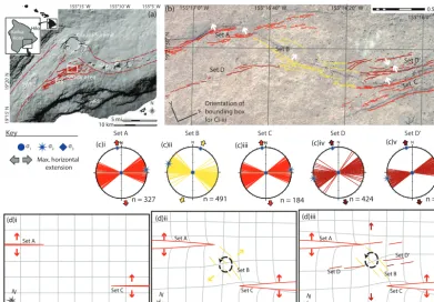
Figure 3. (a)Simplified structural element map of K¯ılauea Volcano, showing the study area within the Koa‘e fault system (KFS). ERZ: East Rift Zone. SWRZ: Southwest Rift Zone. HFS: Hilina Fault System. Inset shows relative position of A, on the south coast of the island of Hawai‘i.(b)WorldView-2 image of the study area showing the distribution and orientation of mapped fractures. White arrows indicate dip directions of monocline limbs and fault scarps.(c)Lower-hemisphere stereographic projections showing measured fault and/or fractures as planes and measured extension directions for each of the three structural sets.(d)Proposed schematic evolution of fault sets: (i) propagation of the main rift-fault set (sets A and C); (ii) interaction between sets A and C produces deficits of heave displacement, requiring vertical axis block rotation in the relay zone, and local reorientation of extension direction (set B); and (iii) development of new rift-parallel structures (set D; Swanson et al., 2017). The bounding box is aligned with first-order rift faults (sets A and C).
Based on orientation, extension direction, and spatial dis-tribution, we identify two dominant fault and fracture sets in the Koa‘e fault system: (1) ENE–WSW-striking (ERZ par-allel) first-order fractures and normal faults that accommo-date the regional NNW–SSE extension (sets A, C, and D; Fig. 3b) and (2) NW–SE-striking (ERZ-oblique) fractures that accommodate a more localized NE–SW extension (set B; Fig. 3b). The NW–SE-striking (ERZ-oblique) fractures (set B) are not ubiquitous throughout the Koa‘e fault sys-tem. Instead they are restricted to zones of underlap between first-order rift faults: here, in the underlap between two ma-jor ENE–WSW-striking (ERZ-parallel) normal faults: sets A and C (Figs. 2 and 3). NW–SE-striking fractures are therefore described as second-order structures, ancillary to first-order bounding rift faults (sets A and C). All measured fractures in this NW–SE-striking set (set B) show purely extensional opening (Fig. 3b), resulting in a local extension direction that is ∼40◦clockwise of the regional (NNW–SSE) exten-sion. We found no evidence for cross-cutting relationships between ENE–WSW- and NW–SE-striking fracture sets (sets A, C, and B; Fig. 3c(i, ii)). Measurements of fresh ground
cracks following the last major rifting event that affected the Koa‘e (December 1965) identified fresh ENE–WSW-striking extension fractures (here labelled set D; Fig. 3b, c(iii); Swan-son et al., 2017), at which time fault and fracture sets A, B, and C had already been mapped; we infer here that these ex-isting sets either formed in a cyclic sequence or formed con-temporaneously.
in-for a coherent fault array
0 200 400 600
200 400 600 800 2400
0 1000 1200 1400 1600 1800 2000 2200
Set A Set B
Length (m)
)
m(
ec
nat
si
D
Set C
0 1 2 3 4 5 6
0 200 400 600 800 1000 1200 1400 1600 1800 2000 2200 2400
Extension
(m)
Length (m)
Total measured extension Resolved rift-zone-normal extension Resolved rift-zone-parallel extension
(a)
(b)
(c)
Set A Set B Set C
0 2 4 6 8 10 12
0 100 200 300 400 500 600 700 800 900 1000 1100 1200 1300 1400 1500 1600 1700 1800 1900 2000 2100 2200 2400
Set A Set B Set C
Length (m)
Fault dip
Fault dip Fault dip
Set D Set D
No elevation data
Fault dip
200 m
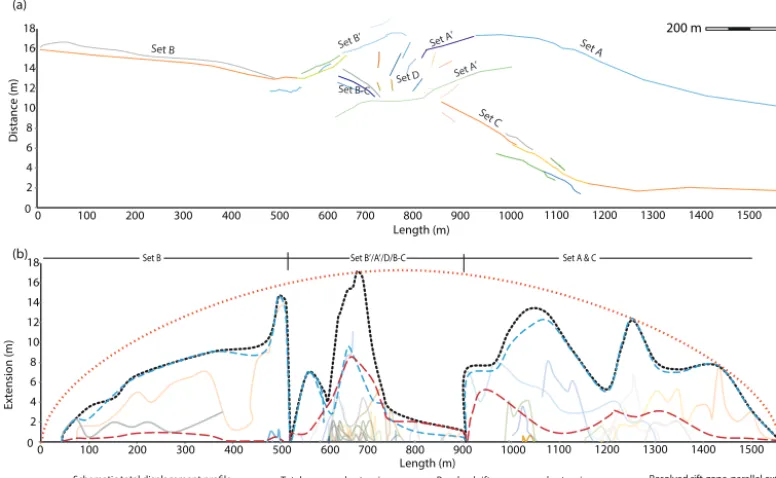
Figure 4. (a) Distribution of mapped fractures in the study area. (b)Profile of horizontal displacement (heave) vs. length for mapped fractures. The dotted grey line indicates cumulative aperture for each set. Dashed blue lines indicate the calculated component of rift-zone-normal extension on each fracture set. Dashed red lines indicate the calculated component of rift-zone-parallel extension on each fracture set. The dotted orange line represents a hypothetical total displacement profile for a single fault (e.g. Gupta and Scholz, 2000), or fully linked, mature fault array (e.g. Childs et al., 2017), in which the maximum displacement is located centrally along the fault or array.(c)Profile of estimated vertical displacement (monocline height and throw) vs. length for segments of surface-breaking faults. No evidence for throw was identified along the NW–SE-striking fractures of set B. With no surface-breaching fault segments along the NW–SE-striking fractures of set B, we present monocline height values only. The dotted line indicates extent of elevation data when the profile is estimated from field observations and aerial imagery.
terpret this zone of underlap to be a relay zone, bound by fault sets A and C.
Figure 4 shows the summed surface extensional strains for each fracture set in the mapped area, as a function of the total plane-normal extension (i.e. extension measured in the dip azimuth), and the resolved contribution to NNW–SSE (re-gional) extension. Extension on set B fractures is in deficit compared to the surrounding regions with a total measured heave (aperture) peak of∼3.5 m compared to∼6 m for the northern bounding set A and 4.5 m for the southern bound-ing set C (Fig. 4b). A vertical displacement (throw) deficit is also recognized (Fig. 4c) from aerial lidar datasets with up to∼12 m of displacement measured across fault A and up to∼4 m across fault C and the monocline along fracture set B. The relative contributions of the components of rift-zone-normal and rift-zone-parallel extension also follow this dis-tribution with a centrally located minimum of 3 m (rift-zone-normal extension) on linking set B. This minimum is bound to the north by∼5 m of rift-normal extension on set A and
∼4 m on set C to the south. Calculated rift-zone-parallel
ex-tension is minor on southern bounding set C (up to 1.2 m) and peaks are approximately equal on the linking set B and north-ern bounding set A (up to 2.5 m). Although set B accom-modates a component of rift-zone-normal extension, this set contributes relatively little to the regional extensional strain as a whole (Fig. 4b, c).
4.1.2 The Krafla fissure swarm, Iceland
Key
(e)i (e)ii (e)iii
σ1
σ2
σ3
Max. horizontal extension
16˚47” W
0.2 k
m
0.1 mi
(c) (a)
65°50’45” N
N
16°50” W 16°40” W Kra a
Theistar
eyk
ir
1984 La
va
Gjast
yk
ki V
alley
C
5 k
m
2.5 mi
(b)
N
N
n = 25 (d)iii
N
n = 11 (d)ii
N
n = 32 (d)i
HF GF DF
RR
KR
Th Kr Fr
As
Reykjavik
Akureyri
NVZ
EVZ WVZ
N N N
Set A
Set B
Set C
Set D Set A
’ Set A
’
Set B’
Set B-C
Set A
Set B
Set A
Set B
Set C Set C
Set A ’
Set B ’
Set D
Set B -C
Set B Set A
Set A ’
Set B ’
Set D
65°50’30” N
65°51’ N
y
x Orientation of bounding box for Ei-iii
study area is a relay zone surrounding the tips of en éch-elon rift-zone-parallel normal faults that strike NNE–SSW (Fig. 5b, c).
Faults and footwall fractures in the Krafla system can be separated into three structural sets based on their orienta-tion, extension direcorienta-tion, and extension mode (Fig. 5c, d): (1) NNE–SSW-striking (parallel to the rift axis: sets A, B, C) first-order fractures and normal faults, which accommo-date rift-zone-normal (WNW–ESE) extension; (2) NW–SE-striking (rift-oblique: sets A’, B’) normal faults and mixed-mode (extensional shear) fractures that accommodate rift-zone-oblique (ENE–WSW) extension; and (3) WNW–ESE-striking (normal: set D) fractures that accommodate rift-zone-parallel (NNE–SSW) extension. The distribution of NW–SE (sets A’, B’) and WNW–ESE-striking (set D) frac-tures is limited to a zone of underlap ahead of two first-order rift-parallel normal faults (sets A and B). Both the NW–SE and WNW–ESE sets are cut by a NNE–SSW-striking nor-mal fault showing up to 2 m of throw and a set of frac-tures with up to 3 m of aperture (set B-C). These later struc-tures connect NW–SE-striking sets B’ and A’ and accommo-date rift-zone-normal extension. Hence, rift-parallel-striking faults and fractures, which cut, and are cut by, obliquely ori-ented sets, are the first and final stages of observed defor-mation in the rift zone, respectively (Fig. 5e). No consis-tent cross-cutting relationships are observed between rift-oblique- and rift-normal-striking structures (Fig. 5e), sug-gesting that they formed contemporaneously.
Figure 6 shows the summed extensional strains for each fracture set in the mapped area, as a function of the plane-normal extension, and the resolved contribution to WNW– ESE (regional) extension. Rift-oblique-striking fault and fracture sets (sets A’, B’; Figs. 5c, 6a) are well-developed and branch away from the tips of rift-parallel-striking faults, with tensile openings of up to∼8 m (Fig. 6b) and estimated maximum throws of ∼20 m. Rift-normal-striking fractures (set D; Figs. 5c, 6a) represent the smallest strains in the relay zone with maximum fracture apertures of up to 2 m (Fig. 6b) and no vertical displacement (throw). Based on the total measured extension profile (grey dotted line in Fig. 6b), which represents a fully linked fault array that accommodates regional extensional strain, the underlap zone does not ap-pear to be in deficit compared to the surrounding regions. There is an approximately centralized total aperture peak of
∼14 m, compared to 8 m for southern bounding set B and 13.5 m for northern bounding sets A and C (Fig. 6b). When the directional components of this total measured extension are plotted, however, we are able to define a pronounced heave deficit in the relay zone (blue and red dashed lines in Fig. 6b). Resolved rift-zone-normal extension is greatest on northern bounding sets B and C (∼12 m), followed by southern bounding set B (∼10 m), with a low of ∼9 m to-tal aperture for linking fault and fracture sets (A’, B’, D, B-C; Fig. 6b) in the overlap zone. Rift-zone-parallel extension within the relay zone is significant for the area at∼8 m,
com-pared to a maximum of 1 m for southern bounding set B and a maximum of 5.5 m for northern bounding sets A and C.
4.1.3 Summary and interpretations for the Koa‘e and Krafla fault systems
Regional extension in the Koa‘e and Krafla fault systems is accommodated by segmented rift-zone-parallel faults that are discontinuous and underlapping at the present-day to-pographic surface. Relay zones, located between the lateral terminations of first-order bounding rift faults, transfer dis-placement across second-order, ancillary faults and fractures that strike obliquely and normal to the bounding fault seg-ments. Profiles of displacement (extension) length show an extension deficit in the regional extensional strain, relative to a theoretical displacement profile for fully linked fault ar-ray (Figs. 4b and 6b). Fracture sets that strike at a low angle to the main rift zone (< 45◦) show extensional-shear open-ing (e.g. Krafla; Fig. 5) and must therefore accommodate a combined rift-zone-normal extension direction (i.e. con-tributing to the regional extension) and a component of rift-zone-parallel shortening. Fracture sets that strike at high an-gles (i.e. > 45◦) to the main rift-parallel faults are dominantly extensional and therefore provide a smaller contribution to the regional extension but nevertheless represent a signifi-cant component of rift-zone-parallel extensional strain. Si-multaneous orthogonal extension directions produce an area of inherently 3-D strain within the relay zones.
Observed rift-oblique extensional-shear fault and fracture sets are dominantly synthetic to each other, rather than bi-modal (i.e. conjugate). As such, we infer that they facilitate a vertical axis rotation between the main rift faults, simi-lar to a bookshelf-like faulting mechanism (Mandl, 1987). A bookshelf rotation about a vertical axis would involve a zone-normal material thickening but must also involve a rift-zone-parallel material thinning (cf. bookshelf rotations about a horizontal axis, which accommodate horizontal extension and vertical thinning). Fractures with strikes orthogonal to the main rift faults in the Krafla study area, however, display extensional openings that may counteract this shear-induced shortening, leading to an overall volume increase within the rift zone. At the surface, this volume increase is accommo-dated by open cracks, but may be accommoaccommo-dated in the sub-surface by normal faults and dike emplacement oblique to and normal to the rift axis.
1100 1200 1300 1400 1500 1600
700 800 900 1000
Set B Set B’/A’/D/B-C Set A & C
Length (m) 0
2 4 6 8 10 12 14 16 18
0 100 200 300 400 500 600
Extension (m)
(a)
(b)
Set B Set B’
Set C
1100 1200 1300 1400 1500 1600
700 800 900 1000
0 2 4 6 8 10 12 14 16 18
0 100 200 300 400 500 600
Set A’
Set A
Set D
Set A’
Set B-C
for a coherent fault array
Length (m)
Resolved rift-zone-normal extension Resolved rift-zone-parallel extension Total measured extension
200 m
)
m(
ec
nat
si
D
Figure 6. (a)Distribution of mapped faults and fractures in the study area.(b)Profile of horizontal displacement (extension or heave) vs. length for mapped fractures. The dotted black line indicates the total measured extension for structures in each set. Dashed blue lines indicate the calculated component of extension on each fracture set that occurs in a direction orthogonal to the rift zone. Dashed red lines indicate the calculated component of extension on each fracture set that occurs in a direction parallel to the rift zone. Extension across the system as a whole is represented by a hypothetical displacement profile for a fully linked, mature fault array in which the maximum displacement is located centrally along the fault, or array, and tapers to zero at the lateral tips (dotted orange line).
the SW termination of the Ægir spreading ridge segment and NE termination of the Reykjanes Ridge segment (Fig. 7a), and both ridges record the initiation of oceanic spreading in the early Ypresian (∼55–53 Ma; Gernigon et al., 2012) (Fig. 7c). Prior to NE Atlantic spreading, the Faroe Islands and Kangerlussuaq were located about 80 km apart (Ellis and Stoker, 2014). The two regions can therefore be considered remnants of a very large (∼5×10⁴km2), breached relay sys-tem between the eventual ridge segments.
Both areas are dominated by Cenozoic North Atlantic Ig-neous Province lavas and intrusions, and both exhibit se-quential deformation phases that are constrained as having formed prior to, and contemporaneous with, Atlantic opening (Walker et al., 2011; Roberts and Walker, 2016; Guarnieri, 2015). Here we present a combination of new geometric and kinematic data for the Kangerlussuaq region of east Green-land, and published data for the Faroe Islands, based on field and remote mapping of upper crustal (1–6 km depth maximum) faults and intrusions. We do not seek to directly compare the scale or regional dynamics of continental mar-gins with volcanic island faulting or mid-ocean ridges, but rather the kinematic evolution of segmented fault systems. Our comparison is between the surface expression of fault sets (Koa‘e and Krafla) and near-surface brittle deformations
on the Atlantic margins. We do not seek here to address full crustal thickness stretching models.
4.2.1 Kangerlussuaq, east Greenland Atlantic margin Igneous activity in the Kangerlussuaq region of east Green-land (Fig. 8a), associated with continental break-up, is thought to have occurred in three phases: 62–59, 57–54, and 50–47 Ma (Tegner et al., 1998), with emplacement of the 7 km wide, layered gabbroic Skaergaard intrusion at∼56 Ma (Wotzlaw et al., 2012). Deformation is characterized by ge-ometrically and temporally linked suites of cross-cutting faults and dikes, hosted within the Archaean basement and Cretaceous–Cenozoic stratigraphy (Fig. 8b, c). Importantly, faults and dikes cut the Skaergaard intrusion and composi-tionally similar macrodikes (e.g. the Miki Fjord macrodike; Fig. 8a, c) that are thought to be contemporaneous with em-placement of the Skaergaard intrusion (Holm et al., 2006; Holwell et al., 2012), giving a well-constrained maximum age for the deformation.
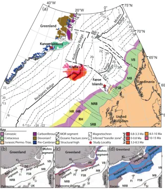
Figure 6. NE Atlantic tectonic elements map: Hatton Rise (HR), Hatton Basin (HB), Rockall High (RH), South Rockall Basin (SRB), North Rockall Basin (NRB), Møre Basin (MB), Vøring Basin (VB), Jan Mayan (JM), Jan Mayan Fracture Zone (JMFZ), Tjornes Fracture Zone (TFZ), Faroes Fracture Zone (FFZ). Map was compiled using: basin ages from Lundin and Doré (1997); oceanic magnetic anomalies from Gaina et al. (2009); Iceland stratigraphic ages from Doré et al. (2008). Study localities indicated by stars. Key Ic eland 0.8-3.3 Ma 0-0.8 Ma 3.3-8.5 Ma 10-15 Ma 8.5-10 Ma Structural high Cenozoic Cretaceous Jurassic/Permo.-Trias. MOR segment Oceanic fracture zone Carboniferous
Pre-Cambrian Devonian?
Magnetochron Inferred “transfer zone” Study Locality 20 20 0° 20°W W ° 0
4 75N °
70°N 65°N 55°N 60°N TFZ ? ? 6 MB
AegirRidge
MohnsRidge
3
1 20 22
6 22 20 6 FFZ Scandinavia United Kingdom ? ? 20 22 24 6 13 20 22 24 VB 13 RH NRB SRB R
H HB
FSB Faroe Islands JMFZ 20 13 6 Greenland 6 22 20 20 JM Reykjanes Ridge Kolbeinsey Ridge Kangerlussuaq FSB
Greenland Greenland Greenland
No rw ay UK No rw ay No rw ay Kolbeins ey segme nt JM SI SI SI JM
Microcontinents Magnetic isochron Extent of Cretaceous and younger basins
(a)
(b)
JM
FI FI
KL KL KL
FI
(c) (d)
Key
SI
Paleocene Paleocene-Eocene Eocene
FSB MB
VB Mohns segment
Aegir segme nt
Aegir segme nt
Aegir se gment Reykjanes segme nt Reykjanes segme nt Mohns
segment Mohnssegme
nt Reykjanes segme nt NRB FSB MB VB NRB FSB MB VB NRB oes
Figure 7. (a)NE Atlantic tectonic elements map: Hatton Rise (HR), Hatton Basin (HB), Rockall High (RH), South Rockall Basin (SRB), North Rockall Basin (NRB), Faroe–Shetland Basin (FSB), Shetland Islands (SI), Møre Basin (MB), Vøring Basin (VB), Jan Mayen (JM), Jan Mayen Fracture Zone (JMFZ), Tjörnes Fracture Zone (TFZ), and Faroes Fracture Zone (FFZ). The map was compiled using basin ages from Doré et al. (1997), oceanic magnetic anomalies from Gaina et al. (2009), and Iceland stratigraphic ages from Doré et al. (2008). Study localities are indicated by stars.(b–d)Schematic model for a segmented opening of the NE Atlantic during the Paleogene (after Ellis and Stoker, 2014). Faroe Islands (FI); Kangerlussuaq (KL).
conjugate set with ENE–WSW-striking faults, which accom-modates margin-oblique (N–S) extension (Fig. 8d(i)). These faults also cut the Skaergaard intrusion (Fig. 8b) and strike parallel to conjugate dikes, with which they show a mu-tual cross-cutting relationship. Skaergaard additionally hosts margin-normal (N–S to NW–SE) faults and dikes, accommo-dating margin-parallel (NE–SW) extension (Fig. 8b, d(ii)), which are cut by the margin-oblique structures (Fig. 8b). Lo-cally, margin-parallel dikes are observed in the Skaergaard intrusion, which cut both of those sets (see also Irvine et al., 1998).
N
n= 39
n= 63 N N
n= 20 N
Margin-oblique faults/dikes N-S-extension
Margin-parallel faults NW-SE-extension
62°17’30
” N
7°8’ W 7°9’ W
0.2 mi 0.5 km
(d)
0.1 km 0.1 mi
?
Margin-oblique faults/dikes N-S-extension sedimentary
marker horizon
Margin-normal faults NE-SW-extension
6°52’20” W 6°52’10” W 6°52’00” W
61°29’10” N
(c) (b)
(e)i
(e)ii
(e)iii
Margin-normal strike
Margin-oblique strike
Margin-parallel strike
σ1 σ2 σ3
max. horizontal
extension max. horizontalcompression
N N
Enni Fmn
Malinstindur Fmn
Beinisvørð Fmn Hvannhagi Fmn Irregular Sills Key
Sneis Fmn Mapped fault/dyke
Pres
190 0
Bathymetry Depth / m
20 km 15 mi
Calculated extension directions
Set 1Set 2Set 3
Key
(a)
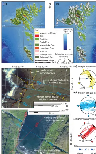
dikes and strike-slip faults (margin-oblique strike; Fig. 9c, d, e(ii)) that accommodate N–S extension; and (3) NE–SW and NNE–SSW-striking strike-oblique-slip faults (margin-parallel strike; Fig. 9d, e(iii)) that accommodate NW–SE ex-tension. Walker et al. (2011) interpreted the fault and intru-sion sets as representing a progressive anticlockwise rota-tion in the extension direcrota-tion before, during, and follow-ing continental break-up. Set 1 (NW- and N-strikfollow-ing) faults are associated with thickness variations in the Faroe Islands Basalt Group (Passey and Jolley, 2009), suggesting that they are Paleocene in age. Using U–Pb geochronology for calcite-bearing fault rocks, Roberts and Walker (2016) showed that although dating of set 2 (ENE- and ESE-striking) faults sug-gest they are mid-Eocene in age, there was potential for overlap with the ages of set 3 faults (Eocene and Miocene). Roberts and Walker (2016) were unable to constrain ages for set 1 faults, primarily due to high concentrations of common Pb and very low U concentration within the tested calcite. Margin-parallel (NE–SW-striking) faults accommodate ex-tension parallel to the regional exex-tension (i.e. NW–SE). The apparently oldest structures strike NW–SE and are parallel to postulated margin-normal strike-slip (transfer) fault zones reported along the margin (e.g. Ellis et al., 2009). In the Faroe Islands, this set accommodates minor (∼1 %) exten-sion parallel to the margins and not strike-slip displacement. The prevalent strain recorded on the Faroe Islands, in terms of distribution and scale of displacements, is associated with the phase of N–S extension, in which ENE–WSW and ESE– WNW conjugate dikes and strike-slip faults accommodate large lateral displacements (potentially up to hundreds of me-tres).
4.2.3 Summary and interpretations for Kangerlussuaq and the Faroe Islands
Faults and intrusions in Kangerlussuaq and the Faroe Is-lands record a consistent vertical axis rotation in extensional strains through time during a period of regional-scale NW– SE extension (Walker et al., 2011). Structures that strike at a high-angle to the NE–SW-trending rift segments (i.e. NW–SE-striking structures) accommodate NE–SW (rift par-allel) extension (Figs. 8d, 9e), rather than the dominantly strike-slip displacements that have been inferred from seis-mic and potential field datasets (e.g. Rumph et al., 1993; El-lis et al., 2009). Structures that strike at angles oblique to the rift segments (i.e. ENE- and ESE-striking faults and intru-sions) accommodate a component of rift-subparallel short-ening and extension oblique to the regional extension vec-tor (Figs. 8d, 9e). Very few structures within the mapped ar-eas accommodate rift-normal extension (NW–SE): the Miki Fjord macrodike accommodates up to ∼500 m horizontal extension, approximately in a NW–SE direction (Fig. 8c). These structures appear to be cut by, and cut, other struc-tural sets, suggesting that they represent the first and final observed structures within the study areas.
5 Discussion
5.1 Rift-zone-parallel extension associated with normal fault and rift systems
The potential for displacement transfer and locally anoma-lous (with respect to far-field stresses), three-dimensional strains during fault linkage has been recognized in field stud-ies (e.g. Ferrill et al., 1999; Ferrill and Morris, 2001; Koehn et al., 2008, 2010; Morris et al., 2014), scaled analogue mod-els (e.g. Tentler and Acocella, 2010) (see Fig. 1), and numer-ical simulations (e.g. Segall and Pollard, 1980; Crider and Pollard, 1998; Kattenhorn et al., 2000; Maerten et al., 2002). For instance, Kattenhorn et al. (2000) demonstrated that, de-pending on the remote stress state, it is possible for a range of ancillary fault or fracture orientations to develop, record-ing variable amounts of extension parallel to the first-order faults. It is likely that such ancillary deformations record a component of bending strain (e.g. deformation bands in the Delicate Arch relay ramp, Arches National Park, Utah; see Rotevatn et al., 2007).
Bending strains are commonly analysed in the vertical plane where bedding is horizontal, but bending in the hori-zontal plane is challenging to identify due to a paucity of ref-erence points. Normal faults in this study demonstrate ver-tical plane bending, about a horizontal axis, but associated with this extension is an observable component of bending in the horizontal plane, about a vertical axis. The development of strains associated with this bending does not develop in-stantaneously, rather each set may grow incrementally with slip accumulation on the bounding first-order faults as the re-lay zone distorts, nor are they restricted to one scale of obser-vation. Such incremental, non-plane strains within evolving relay zones may be responsible for local instances of basin inversion, reverse and strike-slip faulting in otherwise ex-tensional regimes, and complex compartmentalization char-acteristics (e.g. Lin and Okubo, 2016; Sachau et al., 2016). Importantly, for basin faults with displacements on the kilo-metre scale, significant amounts of horizontal bending and rotation are possible, driving associated strains that may go undetected.
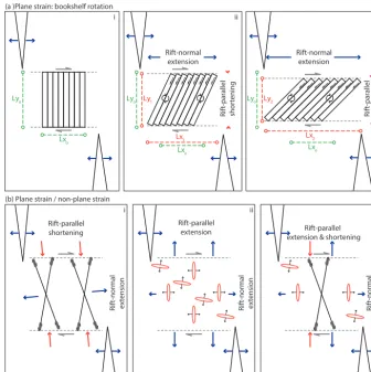
characteris-(a )Plane strain: bookshelf rotation
(b) Plane strain / non-plane strain
Ri
ft-normal extension Rift-parallel
shortening i
Lyo
Lxo
Ri
ft-pa
rallel
sho
rt
ening
ii
Lxo
Lyo Ly1
Lx1 Rift-normal
extension
Ri
ft-pa
rallel
sho
rt
ening
iii
i
Ri
ft-normal extension Rift-parallel
extension
ii
E.g. Hawai`i
Ri
ft-normal extension Rift-parallel
extension & shortening iii Lxo
Lyo Ly2
Lx2 Rift-normal
extension
Figure 10.Horizontal plane 2-D conceptual models for inter-fault and inter-rift relay rotation.(a)Bookshelf rotation model showing (i– iii) progressive rotation leading to rift-normal extension and rift-parallel shortening. (b)Schematic models for structures observed in the study areas presented here: (i) conjugate extensional shear faults, (ii) extension fractures, and (iii) a combination of extension fractures and conjugate extensional shear faults. If faults develop throw, as in the Krafla example, the system becomes non-plane strain. Models are not to scale.
tics similar to those observed in the Koa‘e and Krafla study sites, including (1) segmented bounding faults, (2) progres-sive development of obliquely oriented ancillary fault struc-tures internal to the relay zone that accommodate non-coaxial strains, and (3) rift-zone-parallel connecting faults.
Evidence for vertical axis rotations on the rift zone scale (i.e. tens to hundreds of kilometres) has previously been at-tributed to bookshelf-type faulting models (e.g. Green et al., 2014; Fig. 10a). In such models, a vertical axis rotation can contribute to rift-zone-normal extension. In horizontal axis rotations, via bookshelf faulting, a shear couple in the vertical plane represents a horizontal extension and a vertical short-ening (i.e. crustal thinning). In vertical axis rotation, shorten-ing would require a horizontal material thinnshorten-ing along the rift zone: in plane strain, this would not require vertical crustal thinning. Vertical axis rotations by this mechanism, with a shear couple in the horizontal plane requires horizontal short-ening (Fig. 10). For a rigid block model, the rotation has the effect of causing a material thickening orthogonal to the rift
zone (e.g. Fig. 1e). Figure 1e shows that this rotation also re-sults in material extension parallel to the rift axis, allowing addition of new material as a volume increase; during non-rigid body rotations (e.g. Fig. 10), second-order faults may act to facilitate the coupled components of rift-zone-normal extension and rift-zone-parallel shortening (e.g. Fig. 10b). For faults in the Krafla study area, we infer that rift-zone-parallel shortening is counteracted, contemporaneously, by the extensional component of obliquely oriented extensional shear faults and rift-normal-striking extension fractures at the free surface (e.g. Fig. 10b(iii)). At depth, this volume in-crease could occur as veins and/or dikes.
5.2 A vertical axis rotation model for rift basin segmentation in the NE Atlantic
break-Walls Boundary
Fault Faroe
Islands JL BLWL
CLGKL VL
ML EL Faroe
Platform Fugloy Ridge
M unke
grunnur Ridge
West ShetlandPlatfo rm Faroe
Bank Basin
50 km 0
50 mi
0 N
Shetland Islands
62° N
60° N
0° 2° W 4° W
6° W U.K.
sector Faroes sector
North Atlantic Igneous
Province Cenozoic igneouscentre Cenozoic anticline axis Structural high
Structural lineament Major fault National border Key
(b) (a)
(c)
0.2
km
0.2
km
N
N
N N
Rotate
Reykjanes
Aegir KL
FI Kolbeinsey
Figure 11. (a)Reflection of left-stepping Krafla faults to a right-stepping NE Atlantic rift configuration. (b)Map of the European margin of the NE Atlantic showing the broad NE–SW basin trend. JL: Judd Lineament; CL: Clare Lineament; GKL: Grimur Kamban Lineament; VL: Victory Lineament; EL: Erlend Lineament; ML: Møre Lineament; BL: Brynhild Lineament; WL: Westray Linea-ment.(c)Krafla faults are rotated into the orientation of the Atlantic European margin basin system and compared with the Reykjanes– Ægir system.
up. Structures accommodate extensional strains at a range of angles relative to the regional extension vector (NW–SE) associated with a vertical axis rotation in the maximum hor-izontal stress (Figs. 8 and 9). Here we apply a geometric and kinematic comparison between the observed structures on the Atlantic margins and smaller-scale structures that evolved in regions of extension deficit and rotation in the Koa‘e and Krafla fault systems to consider, by analogy, whether ver-tical axis rotation during extension presents a viable model for strain evolution on a scale of tens of kilometres. We fo-cus on the Krafla system, as the extensional strain accommo-dated there has produced surface breaching structures that are closely comparable to the Atlantic margin.
(a) Faroes & Faroe–Shetland
Basin
(b) Kangerlussuaq
east Greenland (fault trace
rotation) (strike rotation)
(e) All data
? ?
σ1 σ2 σ3 Max. horizontal Max. horizontal extension compression Key:
Figure 12.Comparison of averaged structural orientations and kinematics for the Faroe Islands(a)and east Greenland(b).(c)Krafla data are reflected and rotated so that the surface traces match the NE Atlantic basin system.(d)Krafla data are reflected and rotated so that the measured planar data match the measured data from the NE Atlantic basin system.(e)Combined summary of orientations and kinematics from each study area.
Rift-parallel-striking fault sets along both margins repre-sent the first and final structural set. Timing relationships of fault sets on the Faroe Islands and in east Greenland im-ply a progressive vertical axis stress rotation at the regional scale, which is consistent with models that predict break-up involved a series of initially underlapping rift systems dur-ing rift propagation (Ellis and Stoker, 2014) (Fig. 7b–c). Al-though the history of fault sets in the Krafla relay zone is less clear, the interpreted pattern fits well with the strains observed on a larger scale along the NE Atlantic margins (Fig. 12). We therefore propose that a vertical axis rota-tion model (associated with heave gradients) can account for margin-normal-striking normal faults, dikes, and linea-ments in segmented rift systems and presents a viable alter-native to a polyphase extension and reorganization, or strike-slip – transfer – models, that has been applied previously (e.g. Ellis et al., 2009). Our new model, however, cannot and should not be applied along the entire length of the European margin in a simple way. Along this margin seg-mentation styles vary considerably, from large-scale, local-ized transform faults, e.g. the Jan Mayen Fracture Zone, or the Senja Fracture Zone in the Norwegian–Greenland seas (e.g. Skogseid and Eldholm, 1987; Gernigon et al., 2009), to
development of transform faults that link the offset accret-ing segments (Gerya, 2012, 2013). With estimated crustal thicknesses in the NE Atlantic varying from ∼3–10 km in the Norwegian–Greenland seas to∼10–35 km in the Rock-all Basin and the Greenland–Iceland–Faroes Ridge (SmRock-all- (Small-wood and White, 2002; Gernigon et al., 2009), variations in axis-parallel segmentation patterns are to be expected (e.g. Hayward and Ebinger, 1996). Localized and large-scale frac-ture zones along the NE Atlantic margins only occur where crustal thicknesses fall below 10 km; elsewhere we find thick crust and distributed fault systems that are dominated by ac-commodation zone-style stress transfer, rather than regional-scale strike-slip faults. The protracted extensional history of the region and superposition of NE Atlantic rifting on Pa-leozoic rift systems, themselves influenced by Caledonian and/or older fabrics, mean that pre-existing structural weak-nesses are likely to be widespread along the margin (e.g. Doré et al., 1999), and the style of segmentation appears to vary considerably. Although the controls on segmentation style in the NE Atlantic are beyond the scope of this study to investigate, it is nevertheless important to consider the poten-tial role of factors such as pre-existing structures, strain rate, or crustal thickness when applying any single model to the entire margin.
6 Conclusions
Discontinuous normal faults in the Koa‘e and Krafla fault systems accommodate regional horizontal extensional strains via a combination of fault throw and heave on first-order rift faults. Obliquely oriented second-order deformation is driven by extension gradients and vertical axis block rotation within the intervening relay zones.
Second-order faults and fractures serve to accommodate components of the regional extension and, variably, a com-ponent of shortening and extension in a direction parallel to-and oblique to the rift zone.
Fault population heterogeneity within relay zones is at-tributed to locally non-coaxial stress states associated with mechanical interaction and resulting fault displacement gra-dients, rather than regional-scale polyphase tectonic episodes or changes in the remote stress field.
Relay zones are considered to occur across most scales of segmented extensional systems; thus, we infer that verti-cal axis block rotations and the associated loverti-cal deformation, which accommodate deficits in fault heave, occur within the same range of scales. The distribution of second-order struc-tures is controlled by the scale of segmentation.
A displacement deficit-rotation model is applied to the NE Atlantic margins, in which second-order fault sets locally ac-commodate margin-parallel extension and shortening during vertical axis rotation. We show that this is a viable alterna-tive model to explain the upper crustal geometry, kinematics, and timing of structures versus existing strike-slip (transfer)
segmentation models for the case study presented, but urge caution in applying the model along the length of a given system.
Data availability. Raw data for study sites on the Faroe Islands are published in Walker (2010) and Walker et al. (2011). Field locations may be found in Figs. 3, 5, 8, and 9. Raw data are not currently available due to ongoing data analysis but will be made available to the broader community in due course. For specific requests in the meantime, please contact A. Bubeck ([email protected]).
Author contributions. Data from Hawai‘i and Iceland were lected by AB. Data from the Faroe Islands and Greenland were col-lected by RW. RH and JI provided valuable discussion. CM and DH assisted with data collection and contributed to the discussion. AB prepared the paper with contributions from all co-authors.
Competing interests. The authors declare that they have no conflict of interest.
Acknowledgements. This study was funded via Richard J. Walker’s University of Leicester start-up fund, as part of Alodie Bubeck’s PhD project. Observations crucial to this study were made during Richard J. Walker’s PhD research, which was funded by Statoil (UK) Ltd. Thanks to Pierpaolo Guarnieri for making it possible to collect data in east Greenland, and thank you to the Føroya Dàtusavn for access to Faroes aerial imagery. We thank Richard England for discussions during manuscript preparation. We thank reviewers Atle Rotevatn and Lucia Perez-Diaz for constructive feedback, which greatly improved the clarity of this manuscript. We gratefully acknowledge Don Swanson (HVO) and Mike Poland (formerly HVO) for their help and advice during fieldwork planning and data collection, and we thank the National Park Service for granting a research permit to conduct fieldwork in the Koa‘e fault system. Aerial lidar datasets were provided by the OpenTopography Facility with support from the National Science Foundation under NSF award nos. 1226353 & 1225810 (not related to this study).
Edited by: Gwenn Peron-Pinvidic
Reviewed by: Atle Rotevatn and Lucia Perez-Diaz
References
Ackermann, R. V. and Schlische, R. W.: Anticlustering of small nor-mal faults around larger faults, Geology, 25, 1127–1130, 1997. Ackermann, R. V., Schlische, R. W., and Withjack, M. O.: The
ge-ometric and statistical evolution of normal fault systems: an ex-perimental study of the effects of mechanical layer thickness on scaling laws, J. Struct. Geol., 23, 1803–1819, 2001.
In-sights from analogue models, J. Struct. Geol., 27, 397–408, https://doi.org/10.1016/j.jsg.2004.11.006, 2005.
Carbotte, S. M. and Macdonald, K. C.: Comparison of seafloor tec-tonic fabric at intermediate, fast, and super fast spreading ridges: Influence of spreading rate, plate motions, and ridge segmenta-tion on fault patterns, J. Geophys. Res.-Solid Earth, 99, 13609– 13631, https://doi.org/10.1029/93jb02971, 1994.
Cartwright, J., Mansfield, C. S., and Trudgill, B.: The growth of normal faults by segment linkage, in: Modern Developments in Structural Interpretation, Validation and Modelling, edited by: Buchanan, P. G. and Nieuland, D. A., Vol. Geological Society Special Publication No. 99, London, UK, The Geological Soci-ety, 1996.
Casey, M., Ebinger, C., Keir, D., Gloaguen, R., and Mohamed, F. (Eds.): Strain accommodation in transitional rifts: extension by magma intrusion and faulting in Ethopian rift magmatic seg-ments. Geological Society, London, Special Publications, Vol. 259, The Geological Society of London, 2006.
Childs, C., Watterson, J., and Walsh, J. J.: Fault overlap within de-veloping normal fault systems, J. Geol. Soc., London, 152, 535– 549, 1995.
Childs, C., Holdsworth, R. E., Jackson, C. A. L., Manzocchi, T., Walsh, J. J., and Yielding, G.: Introduction to the geometry and growth of normal faults. Geological Society, London, Spe-cial Publications, 439, 1–9, 5 September 2017, available at: https://doi.org/10.1144/SP439.24, 2017.
Corti, G., Bonini, M., Conticelli, S., Innocenti, F., Manetti, P., and Sokoutis, D.: Analogue modelling of continental extension: a re-view focused on the relations between the patterns of deforma-tion and the presence of magma, Earth-Sci. Rev., 63, 169–247, https://doi.org/10.1016/s0012-8252(03)00035-7, 2003.
Cowie, P.: Normal fault growth in three-dimensions in continen-tal and oceanic crust, in: Faulting and magmatism at mid-ocean ridges, edited by: Buck, W. R., Delaney, P. T., Karson, J. A., and Lagabrielle, Y., Washington, D.C. American Geophysical Union, https://doi.org/10.1029/GM106p0027, 1998.
Cowie, P. A. and Scholz, C. H.: Physical explanation for the displacement-length relationship of faults using a post-yield fracture mechanics model, J. Struct. Geol., 14, 1133–1148, https://doi.org/10.1016/0191-8141(92)90065-5, 1992.
Crider, J. G. and Pollard, D. D.: Fault linkage: Three-dimensional mechanical interaction between echelon normal faults, J. Geophys. Res., 103, 24373, https://doi.org/10.1029/98jb01353, 1998.
Dauteuil, O., Angelier, J., Bergerat, F., Verrier, S., and Villemin, T.: Deformation partitioning inside a fissure swarm of the northern icelandic rift, J. Struct. Geol., 23, 1359–1372, 2001.
Doré, A. G., Lundin, E. R., Birkeland, O., Eliassen, P. E., and Jensen, L. N.: The NE Atlantic margin; im-plications of late Mesozoic and Cenozoic events for hydrocarbon prospectivity, Petrol. Geosci., 3, 117–131, https://doi.org/10.1144/petgeo.3.2.117, 1997.
Doré, A. G., Lundin, E. R., Jensen, L. N., Birkeland, Ø., Eliassen, P. E., and Fichler, C.: Principal tectonic events in the evolution of the northwest European Atlantic margin, in: Geological so-ciety, London, petroleum geology conference series, 5, 41–61, Geological Society of London, 1999.
Doré, A. G., Lundin, E. R., Kusznir, N. J., and Pascal, C.: Poten-tial mechanisms for the genesis of Cenozoic domal structures
on the NE Atlantic margin: pros, cons and some new ideas. Geological Society, London, Special Publications, 306, 1–26, https://doi.org/10.1144/sp306.1, 2008.
Dzurisin, D., Koyanagi, R. Y., and English, T. T.: Magma supply and storage at Kiluea Volcano, Hawaii, 1956–1983, J. Volcanol. Geotherm. Res., 21, 177–206, 1984.
Ellis, D. and Stoker, M. S. (Eds.): The Faroe-Shetland Basin: a re-gional perspective from the Paleocene to the present day and its relationship to the opening of the North Atlantic Ocean, in: Hy-drocarbon exploration to exploitation West of Shetlands, edited by: Cannon, S. J. C. and Ellis, D., Geological Society, London, Special Publications (Vol. 397), The Geological Society of Lon-don, 2014.
Ellis, D., Passey, S. R., Jolley, D. W., and Bell, B. R.: Transfer zones: the application of new geological information from the Faroe Islands applied to the offshore exploration of intra and sub-basalt strata, Paper presented at the Faroe Islands exploration conference: proceedings of the 2nd conference, Torshavn, Faroe Islands, 2009.
Faulds, J. E. and Varga, R. J.: The role of accommodation zones and transfer zones in the regional segmentation of extended terranes, in: Accommodation zones and transfer zones: the regional seg-mentation of the Basin and Range Province, edited by: Faulds, J. E. and Stewart, J. H., Boulder, Colorado (Vol. 323): Geological Society of America Special Paper, 1998.
Ferrill, D. A. and Morris, A. P.: Displacement gradient and defor-mation in normal fault systems, J. Struct. Geol., 23, 619–638, 2001.
Ferrill, D. A., Stamatakos, J. A., and Sims, D.: Normal fault corru-gation: implications for growth and seismictiy of active normal faults, J. Struct. Geol., 21, 1027–1038, 1999.
Fossen, H. and Rotevatn, A.: Fault linkage and relay structures in extensional settings – A review, Earth-Sci. Rev., 154, 14–28, https://doi.org/10.1016/j.earscirev.2015.11.014, 2016.
Gaina, C., Gernigon, L., and Ball, P.: Palaeocene-Recent plate boundaries in the NE Atlantic and the formation of the Jan Mayen microcontinent, J. Geol. Soc., 166, 601–616, https://doi.org/10.1144/0016-76492008-112, 2009.
Gawthorpe, R. L. and Hurst, J. M.: Transfer zones in exten-sional basins: their structural style and influence on drainage development and stratigraphy, J. Geol. Soc., 150, 1137–1152, https://doi.org/10.1144/gsjgs.150.6.1137, 1993.
Gernigon, L., Olesen, O., Ebbing, J., Wienecke, S., Gaina, C., Mo-gaard, J. O., Sand, M., and Myklebust, R.: Geophysical insights and early spreading history in the vicinity of the Jan Mayen Fracture Zone, Norwegian–Greenland Sea, Tectonophysics, 468, 185–205, 2009.
Gernigon, L., Gaina, C., Olesen, O., Ball, P. J., Péron-Pinvidic, G., and Yamasaki, T.: The Norway Basin revisited: From continental breakup to spreading ridge extinction, Mar. Petrol. Geol., 35, 1– 19, https://doi.org/10.1016/j.marpetgeo.2012.02.015, 2012.
Gerya, T.: Origin and models of oceanic
trans-form faults. Tectonophysics, 522–523, 34–54,
https://doi.org/10.1016/j.tecto.2011.07.006, 2012.
Grant, J. V. and Kattenhorn, S. A.: Evolution of vertical faults at an extensional plate boundary, southwest Iceland, J. Struct. Geol., 26, 537–557, https://doi.org/10.1016/j.jsg.2003.07.003, 2004. Green, R. G., White, R. S., and Greenfield, T.: Motion in the north
Iceland volcanic rift zone accommodated by bookshelf fault-ing, Nature Geosci., 7, 29–33, https://doi.org/10.1038/ngeo2012, 2014.
Guarnieri, P.: Pre-break-up palaeostress state along the East Green-land margin, J. Geol. Soc., 172, 727–739, 2015.
Gupta, A. and Scholz, C. H.: A model of normal fault interaction based on observations and theory, J. Struct. Geol., 22, 865–879, 2000.
Hayward, N. J. and Ebinger, C. J.: Variations in the along-axis segmentation of the Afar Rift system, Tectonics, 15, 244, https://doi.org/10.1029/95tc02292, 1996.
Henstra, G. A., Rotevatn, A., Gawthorpe, R. L., and Ravnås, R.: Evolution of a major segmented normal fault during multi-phase rifting: The origin of plan-view zigzag geometry, J. Struct. Geol., 74, 45–63, 2015.
Holland, M., Urai, J. L., and Martel, S. J.: The internal structure of fault zones in basaltic sequences, Earth Planet. Sci. Lett., 248, 301–315, 2006.
Holm, P. M., Heaman, L. M., and Pedersen, L. E.: Badde-leyite and zircon U–Pb ages from the Kærven area, Kanger-lussuaq: Implications for the timing of Paleogene continen-tal breakup in the North Atlantic, Lithos, 92, 238–250, https://doi.org/10.1016/j.lithos.2006.03.035, 2006.
Holwell, D. A., Abraham-James, T., Keays, R. R., and Boyce, A. J.: The nature and genesis of marginal Cu–PGE–Au sul-phide mineralisation in Paleogene Macrodykes of the Kanger-lussuaq region, East Greenland, Mineralium Deposita, 47, 3–21, https://doi.org/10.1007/s00126-010-0325-4, 2012.
Hus, R., De Batist, M., Klerkx, J., and Matton, C.: Fault linkage in continental rifts: structure and evolution of a large relay ramp in Zavarotny; Lake Baikal (Russia), J. Struct. Geol., 28, 1338–1351, https://doi.org/10.1016/j.jsg.2006.03.031, 2006.
Irvine, T. N., Andersen, J. C. Ø., and Brooks,
C. K.: Geological Society of America
Bul-letin, 110, 1398,
https://doi.org/10.1130/0016-7606(1998)110<1398:ibabwb>2.3.co;2, 1998.
Kattenhorn, S. A., Aydin, A., and Pollard, D. D.: Joints at high an-gles to normal fault strike: an explanation using 3-D numerical models of fault-perturbed stress fields, J. Struct. Geol., 22, 1–23, 2000.
Koehn, D., Aanyu, K., Haines, S., and Sachau, T.: Rift nucle-ation, rift propagation and the creation of basement micro-plates within active rifts, Tectonophysics, 458, 105–116, https://doi.org/10.1016/j.tecto.2007.10.003, 2008.
Koehn, D., Lindenfeld, M., Rümpker, G., Aanyu, K., Haines, S., Passchier, C. W., and Sachau, T.: Active transsection faults in rift transfer zones: evidence for complex stress fields and im-plications for crustal fragmentation processes in the western branch of the East African Rift, Int. J. Earth Sci., 99, 1633–1642, https://doi.org/10.1007/s00531-010-0525-2, 2010.
Lambiase, J. J. and Bosworth, W.: Structural controls on sedimen-tation in continental rifts, in: Hydrocarbon habitat in rift basins, edited by: Lambiase, J. J., Vol. Geological Society Special Pub-lications No. 80, London, UK: The Geological Society, 1995.
Lin, G. and Okubo, P. G.: A large refined catalog of earthquake re-locations and focal mechanisms for the Island of Hawai‘i and its seismotectonic implications, J. Geophys. Res.-Solid Earth, 121, 5031–5048, https://doi.org/10.1002/2016jb013042, 2016. Long, J. J. and Imber, J.: Geometrically coherent
continu-ous deformation in the volume surrounding a seismically imaged normal fault-array, J. Struct. Geol., 32, 222–234, https://doi.org/10.1016/j.jsg.2009.11.009, 2010.
Long, J. J. and Imber, J.: Geological controls on fault relay zone scaling, J. Struct. Geol., 33, 1790–1800, https://doi.org/10.1016/j.jsg.2011.09.011, 2011.
Macdonald, K. C.: Linkages between faulting, volcanism, hy-drothermal activity and segmentation on fast spreading cen-ters, in: Faulting and magmatism at mid-ocean ridges, edited by: Buck, W. R., Delaney, P. T., Karson, J. A., Lagabrielle, Y., Washington, D.C.: American Geophysical Union, https://doi.org/10.1029/GM106p0027, 1998.
Macdonald, K. C., Fox, P. J., Alexander, R. T., Pockalny, R., and Gente, P., Volcanic growth faults and the origin of Pacific abyssal hills, Nature, 380, 125–129, 1996.
Maerten, L., Gillespie, P., and Pollard, D. D.: Effects of local stress perturbation on secondary fault development, J. Struct. Geol., 24, 145–153, 2002.
Mandl, G.: Tectonic deformation by rotating parallel faults: the “bookshelf” mechanism, Tectonophysics, 141, 277–316, 1987. Manzocchi, T., Childs, C., and Walsh, J. J.: Faults and fault
properties in hydrocarbon flow models, Geofluids, 10, 94–113, https://doi.org/10.1111/j.1468-8123.2010.00283.x, 2010. Martel, S. J. and Langley, J. S.: Propagation of normal faults to the
surface in basalt, Koae fault system, Hawaii, J. Struct. Geol., 28, 2123–2143, https://doi.org/10.1016/j.jsg.2005.12.004, 2006. Morley, C. K., Nelson, R. A., Patton, T. I., and Munn, S. G.:
Trans-fer zones in the East Africa Rift System and their relevance to hydrocarbon exploration in rifts, The American Association of Petroleum Geologists Bulletin, 74, 1234–1253, 1990.
Morris, A. P., McGinnis, R. N., and Ferrill, D. A.: Fault displacement gradients on normal faults and
associ-ated deformation, AAPG Bulletin, 98, 1161–1184,
https://doi.org/10.1306/10311312204, 2014.
Muirhead, J. D., Kattenhorn, S. A., and Le Corvec, N.: Vary-ing styles of magmatic strain accommodation across the East African Rift, Geochem. Geophy. Geosy., 16, 2775–2795, https://doi.org/10.1002/2015gc005918, 2015.
Passey, S. R. and Jolley, D. W.: A revised lithostratigraphic nomenclature for the Palaeogene Faroe Islands Basalt Group, NE Atlantic Ocean, Earth and Environmental Sci-ence Transactions of the Royal Society of Edinburgh, 99, 127, https://doi.org/10.1017/s1755691009008044, 2009.
Peacock, D. C. P.: Propagation, interaction and linkage in normal fault systems, Earth Sci. Rev., 58, 121–142, 2002.
Peacock, D. C. P.: Scaling of transfer zones in the British Isles, J. Struct. Geol., 25, 1561–1567, https://doi.org/10.1016/s0191-8141(03)00008-7, 2003.
Peacock, D. C. P. and Sanderson, D. J.: Displacements, segment linkage and relay ramps in normal fault zones, J. Struct. Geol., 13, 721–733, 1991.
Bul-letin, 78, 147–165, https://doi.org/10.1306/bdff9046-1718-11d7-8645000102c1865d, 1994.
Peacock, D. C. P., Price, S. P., Whitham, A. G., and Pickles, C. S.: The World’s biggest relay ramp: Hold With Hope, NE Greenland, J. Struct. Geol., 22, 843–850, 2000.
Poland, M. P., Miklius, A., Sutton, A. J., and Thornber, C. R.: A mantle-driven surge in magma supply to Kilauea Volcano during 2003–2007, Nature Geoscience, 5, 295–300, https://doi.org/10.1038/ngeo1426, 2012.
Roberts, N. M. W. and Walker, R. J.: U-Pb geochronology of calcite-mineralized faults: Absolute timing of rift-related fault events on the northeast Atlantic margin, Geology, 44, 531–534, https://doi.org/10.1130/g37868.1, 2016.
Rotevatn, A., Fossen, H., Hesthammer, J., Aas, T. E., and Howell, J. A.: Are relay ramps conduits for fluid flow? Structural analysis of a relay ramp in Arches National Park, Utah, in: Lonergan, L., Jolley, R. J. H., Rawnsley, K., and Sanderson, D. J., Fractured Reservoirs. Geological Society London Special Publication 270, 55–71, The Geological Society, London, 2007.
Rumph, B., Reaves, C. M., Orange, V. G., and Robinson, D. L.: Structuring and transfer zones in the Faeroe Basin in a regional tectonic context, Petroleum Geology Conference Series, 4, 999– 1009, 1993.
Sachau, T., Koehn, D., Stamps, D. S., and Lindenfeld, M.: Fault kinematics and stress fields in the Rwenzori Mountains, Uganda, Int. J. Earth Sci., 105, 1729–1740, https://doi.org/10.1007/s00531-015-1162-6, 2016.
Scholz, C. H. and Contreras, J. C.: Mechanics of continental rift architecture, Geology, 26, 967–970, 1998.
Seebeck, H., Nicol, A., Walsh, J. J., Childs, C., Beetham, R. D., and Pettinga, J.: Fluid flow in fault zones from an active rift, J. Struct. Geol., 62, 52–64, https://doi.org/10.1016/j.jsg.2014.01.008, 2014.
Segall, P. and Pollard, D. D.: Mechanics of Discontinuous Faults, J. Geophys. Res., 85, 4337–4350, 1980.
Sempere, J. C. and Macdonald, K. C.: Overlapping spreading cen-ters: implications from crack growth simulation by the displace-ment discontinuity method, Tectonics, 5, 151–163, 1986. Sharp, I. R., Gawthorpe, R. L., Underhill, J. R., and Gupta,
S.: Fault-propagation folding in extensional settings: Exam-ples of structural style and synrift sedimentary response from the Suez rift, Sinai, Egypt. Geological Society of Amer-ica Bulletin, 112, 1877–1899, https://doi.org/10.1130/0016-7606(2000)112<1877:FPFIES>2.0.CO;2, 2000.
Skogseid, J. and Eldholm, O.: Early Cenozoic crust at the Norwegian continental margin and the conjugate Jan Mayen Ridge, J. Geophys. Res.-Solid Earth, 92, 11471–11491, https://doi.org/10.1029/JB092iB11p11471, 1987.
Smallwood, J. R. and White, R. S.: Ridge-plume interaction in the North Atlantic and its influence on continental breakup and seafloor spreading, in: The North Atlantic Igneous Province: Stratigraphy, Tectonic, Volcanic and Magmatic Processes, edited by: Jolley, D. W. and Bell, B. R., Vol. 197, 15–37, London, UK: The Geological Society of London, 2002.
Swanson, D. A., Fiske, R. S., Thornber, C. R., and Poland, M. P.: Dikes in the Koa‘e fault system, and the Koa’e-east rift zone structural grain at K¯ılauea Volcano, Hawai‘i: Geological Society of America Special Paper, in press, 2017.
Tegner, C., Duncan, R. A., Bernstein, S., Brooks, C. K., Bird, D. K., and Storey, M.: 40Ar-39Ar geochronology of Tertiary mafic in-trusions along the East Greenland rifted margin: Relation to flood basalts and the Iceland hotspot track, Earth Planet. Sci. Lett., 156, 75–88, 1998.
Tentler, T.: Propagation of brittle failure triggered by magma in Ice-land, Tectonophysics, 406, 17–38, 2005.
Tentler, T. and Acocella, V.: How does the initial configu-ration of oceanic ridge segments affect their interaction? Insights from analogue models, J. Geophys. Res., 115, https://doi.org/10.1029/2008jb006269, 2010.
Trudgill, B. and Cartwright, J.: Relay-ramp forms and normal fault linkages. Canyonlands National Park, Utah, Geological Society of America Bulletin, 106, 1143–1157, 1994.
Walker, R. J.: The Structural Evolution of the Faroe Islands, NE At-lantic Margin, Doctor of Philosophy, Durham Univerisity, 2010. Walker, R. J., Holdsworth, R. E., Imber, J., and Ellis, D.: Onshore evidence for progressive changes in rifting directions during con-tinental break-up in the NE Atlantic, J. Geol. Soc., 168, 27–48, https://doi.org/10.1144/0016-76492010-021, 2011.
Walsh, J. J., Bailey, W. R., Childs, C., Nicol, A., and Bonson, C. G.: Formation of segmented normal faults: a 3D perspective, J. Struct. Geol., 25, 1251–1262, 2003.
Willemse, E. J. M., Pollard, D. D., and Aydin, A.: Three-dimensional analyses of slip distributions on normal fault arrays with consequences for fault scaling, J. Struct. Geol., 18, 295– 309, 1996.
Wotzlaw, J. F., Bindeman, I. N., Schaltegger, U., Brooks, C. K., and Naslund, R. H.: High-resolution insights into episodes of crystal-lization, hydrothermal alteration and remelting in the Skaergaard intrusive complex, Earth Planet. Sci. Lett., 355–356, 199–212, https://doi.org/10.1016/j.epsl.2012.08.043, 2012.
Wright, T. L. and Klein, F. W.: Deep magma


![Bis{decacarbonylbis[μ 2,2′ (phenylimino)diethanolato]ditin(II)ditungsten(0)(2 Sn—W)} hexacarbonyltungsten(0)](data:image/gif;base64,R0lGODlhAQABAIAAAP///wAAACH5BAEAAAAALAAAAAABAAEAAAICRAEAOw==)