http://www.sciencepublishinggroup.com/j/wjac doi: 10.11648/j.wjac.20170203.13
Combustion Characteristics and Stability of Methane-Air
Mixtures in Catalytic Microreactors
Junjie Chen
*, Deguang Xu
Department of Energy and Power Engineering, School of Mechanical and Power Engineering, Henan Polytechnic University, Jiaozuo, China
Email address:
jchengn@163com (Junjie Chen)
*
Corresponding author
To cite this article:
Junjie Chen, Deguang Xu. Combustion Characteristics and Stability of Methane-Air Mixtures in Catalytic Microreactors. World Journal of Applied Chemistry. Vol. 2, No. 3, 2017, pp. 85-95. doi: 10.11648/j.wjac.20170203.13
Received: May 28, 2017; Accepted: July 31, 2017; Published: August 22, 2017
Abstract:
Combustion characteristics and stability of premixed methane-air mixtures in catalytic microreactors are studied numerically, using a two-dimensional computational fluid dynamics model with detailed chemistry and multicomponent transport. In order to understand how to design microreactors with enhanced stability and robustness, the reaction and transport of methane-air mixtures are studied, and the role of operating conditions is evaluated. The primary focus is on computational fluid dynamics as a means of understanding energy management at small scales. It is shown that an appropriate choice of the flow velocity is crucial in achieving the self-sustained operation. Large gradients in temperature and species concentration are observed, despite the small scales of the system. The flow velocity plays a dual, competing role in flame stability. Low flow velocities reduce the heat generation, whereas high flow velocities reduce the convective time-scale. There is a narrow regime of flow velocities that allows self-sustained operation. When a low-power system is desired, highly insulating materials should be preferred, whereas a high-power system would favor highly conductive materials. Engineering maps are constructed, and design recommendations are finally made.Keywords:
Catalytic Microreactors, Reactor Design, Combustion Characteristics, Flame Stability, Heat Transfer, Computational Fluid Dynamics Modeling1. Introduction
There has been increasing interest in utilizing the high energy density of hydrocarbon fuels in portable power generation systems [1-6]. One method of generating electricity from hydrocarbon fuels is to use the heat from their combustion to drive endothermic reactions, such as steam reforming of methane [7-12] and ammonia decomposition [13, 14], in integrated micro-chemical systems for the production of hydrogen for fuel cell applications. Furthermore, due to the inherently higher heat-transfer coefficients of these systems, lower combustion temperatures may be envisioned, which can considerably minimize the thermal formation of nitrogen oxides [15, 16].
Unfortunately, the benefits arising at the micro-scale are overshadowed by major difficulties in creating practical systems [2-4]. Depending on flow rate, composition, and geometry, methane-air flames are typically quenched when confined within spaces with critical dimensions of
sub-millimeter [17, 18]. Flames are quenched in these small dimensions due to two main mechanisms, i.e., thermal and radical quenching [15, 19-23]. Thermal quenching occurs when sufficient heat is removed through the system walls, and as a consequence, combustion cannot be self-sustained [15, 20, 22, 24]. Radical quenching occurs through adsorption of radicals on the walls and subsequent recombination, which leads to lack of gas-phase chemistry [15, 19, 21, 23, 25]. The small scales of these systems make them significantly more prone to both quenching mechanisms due to the high surface-area-to-volume ratios, i.e., increased radical mass transfer and enhanced heat transfer from the flame to the walls. In addition to flame quenching, blowout may occur when the exit velocity exceeds the flame burning velocity [20, 22, 24, 26, 27]. In this mechanism, the reaction shifts downstream until it exits the system. The interplay between quenching and blowout has been observed both theoretically and experimentally [28, 29].
Gas-phase combustion provides a high volumetric heat release as compared to catalytic combustion, which is slowed by mass-transfer limitations. However, it has been well established that flames are typically extinguished when confined in gaps of sub-millimeter due to thermal and radical quenching at the system walls [15, 19-25]. These quenching mechanisms become more pronounced as the surface-to-volume ratio increases. Catalytic combustion has the potential to operate at significantly lower temperatures, and with larger heat losses, than gas-phase combustion [30-35]. These features can lead to a wider range of possible construction materials, complete elimination of nitrogen oxides, and increased reactor life [36, 37]. Furthermore, the small length scales increase the transfer rates, which allows for faster catalytic reactions than could be achieved with conventional large-scale devices [38, 39].
While flame propagation at the micro-scale is feasible, the interaction between transport and kinetics in combustion characteristics and stability of these systems is still poorly understood. The inability of conducting spatially resolved measurements, inherent to the micro-scale, underscores the need for detailed computational fluid dynamics modeling [40, 41]. Additionally, due to the high surface-area-to-volume ratio, the potential for the loss of combustion stability needs to be exploited for robust design. Furthermore, to design micro-chemical systems, the effects of wall thermal conductivity and reactor dimension on combustion stability must be explored for optimal thermal management.
In this study, the reaction and transport of methane-air mixtures in catalytic microreactors are studied. Two-dimensional computational fluid dynamics simulations are performed, using detailed reaction mechanisms and multicomponent transport. The effect of operating conditions on the combustion characteristics and stability are delineated. Based on these insights, regions of combustion stability for different design parameters are designated, and operation
diagrams are constructed. Design recommendations are finally made. The objective of this study is on understanding the combustion characteristics in catalytic microreactors. Of special interest is on developing guidelines for appropriate thermal management that can result in more robust flame behavior.
2. Computational Fluid Dynamics Model
Considerable progress has been made on the development of portable power generation systems. In these systems, it is extremely difficult to be able to determine the heat and mass transfer characteristics internal to the reactors. Computational fluid dynamics simulations are critical to understand what is occurring internal to the systems and be able to improve the designs to achieve the desired performance.
2.1. Geometric Model
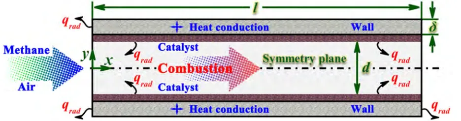
Premixed, stoichiometric methane-air mixtures are fed to a catalytic microreactor, and hot product gases exit. The reactor consists of two parallel, infinitely wide plates of 0.8 mm apart, and length of 5.0 mm. The walls have finite thickness 0.2 mm. Platinum catalysts are coated on the internal walls of the parallel plates. A schematic diagram of the system is shown Figure 1. The arrow indicates the direction of flow. To illustrate the primary mechanism, a relatively simple system may provide valuable insights. The reactor is modeled as a two-dimensional system due to the large aspect ratio. In order to minimize the computational intensity, only half of the system is modeled, given the inherent symmetry of the geometry. The methane fuel is examined, as it is more challenging to the development of micro-power generation due to the significantly increase in reaction time as compared to hydrogen.
Figure 1. Schematic diagram of the catalytic microreactor.
2.2. Mathematical Model
A two-dimensional numerical model is developed using the commercial computational fluid dynamics software ANSYS Fluent, incorporated with detailed chemistry and multicomponent transport. The Reynolds number is less than 800, and thus the laminar flow assumption within the system is valid. Steady-steady simulations are performed. A
finite-volume method is used to discretize the two-dimensional steady-state energy equation in the wall and the two-dimensional steady-state continuity, momentum, energy and species conservation equations in the fluid.
Continuity equation:
( ) ( )
u v 0x y
ρ ρ
∂ ∂
+ =
Momentum equations:
(
) (
)
22 0
3
uu vu p u u v u v
x y x x x x y y y x
ρ ρ
µ µ µ
∂ ∂ ∂ ∂ ∂ ∂ ∂ ∂ ∂ ∂
+ + − − + − + =
∂ ∂ ∂ ∂ ∂ ∂ ∂ ∂ ∂ ∂ (2)
(
) (
)
22 0
3
uv vv p v u v u v
x y y x x y y y x y
ρ ρ
µ µ µ
∂ ∂ ∂ ∂ ∂ ∂ ∂ ∂ ∂ ∂
+ + − + − − + =
∂ ∂ ∂ ∂ ∂ ∂ ∂ ∂ ∂ ∂ (3)
Energy equation:
(
) (
)
, , 1 1 0 g g K Kk k k x g k k k y g
k k
uh vh T T
Y h V Y h V
x y x x y y
ρ ρ ρ λ ρ λ = = ∂ +∂ + ∂ − ∂ + ∂ − ∂ =
∂ ∂ ∂
∑
∂ ∂ ∑
∂ (4)Gas phase species equation:
(
) (
)
(
)
(
)
, , 0
k k
k k x k k y k k
uY vY
Y V Y V W
x y x y
ρ ρ ρ ρ ω
∂ +∂ + ∂ + ∂ − =
∂ ∂ ∂ ∂ ɺ , k=1, ,Kg
…
. (5)
Surface species coverage equations:
0 m m s σ Γ = ɺ
, m=Kg+1,…,Kg+Ks (6)
In the above equations, ρ is the density of the gas mixture, x
and y are the axial co-ordinate and transverse co-ordinate, u
and v are the corresponding flow velocity components, µ is the viscosity of the gas mixture, λg is the thermal conductivity of
the gas mixture, p is the pressure, h is the total enthalpy of the gas mixture, Kg is the total number of gas phase species, T is
the temperature, Yk,
ω
ɺ
k, Wk, and hk are the mass fraction,molar production rate, relative molecular mass, and total enthalpy of the kth gas phase species respectively, and Vk,x, Vk,y
are the x- and y-components of the kth species diffusion velocity. Finally, σm and ṡm denote the number of occupied
surface sites and the molar production rate of the mth surface species, respectively; Ks is the total number of surface species.
Species diffusion velocities Vk are computed using mixture
average diffusion, including thermal diffusion for the light species [42]:
(
)
(
)
( )
, ln ln
T
k k m k k k k
V = −D ∇ Y W W + D W
ρ
Y W ∇ T (7)Here, Dk,m and DkT are the mixture-average diffusion coefficient and thermal diffusion coefficient of kth gaseous species, respectively; and W̄ is the mixture average relative molecular mass.
Since the heat transfer along the walls significantly affects stability [20, 22], the two-dimensional energy equation is explicitly accounted for within the walls:
0
s s
T T
x λ x y λ y
∂ ∂ ∂ ∂
+ =
∂ ∂ ∂ ∂ (8)
Here, λs is the thermal conductivity of the solid wall.
The interfacial boundary conditions for the gaseous species at the specified gas-wall interface (y = d/2) are written as
(
,)
( )
2 2 0 d dk k y y k k y
Y V W s
ρ = + ɺ = =
, k=1,…,Kg (9)
The energy boundary conditions at the specified gas-wall interface (y = d/2) are given as
(
)
2 1 -2 2 0 g K drad g s k k k y
d d k
y y
T T
q s h W
y y λ λ = = = = + ∂ ∂ − + + = ∂ ∂
∑
ɺ ɺ (10)Here, the subscripts (-) and (+) denote the properties just below and above the gas-wall interface, respectively. Radiation heat transfer exchange between the discretized catalytic surface elements as well as between each surface element and the reactor inlet and outlet sections is accounted for by the net radiation method for diffuse-gray areas [43]. The inlet, outlet, and channel-element emissivity is all equal, and the radiation exchange temperatures for the entry and outlet are equal to the corresponding mean gas temperatures. The discrete ordinates radiation model is adopted to model the surface-to-surface radiative heat transfer [44]. The emissivity of each surface element is assumed to be 0.8 [45].
For all the external surfaces, the total heat loss to the surroundings is taken into account:
(
)
(
4 4)
, ,
o w o amb w o amb
q=h T −T +εσ T −T (11)
Here, the external heat loss coefficient ho is assumed to be
20 W/(m2·K) [45]; ε is the surface emissivity; σ is the Stephan-Boltzmann constant; Tamb is the ambient temperature.
2.3. Chemical Kinetics
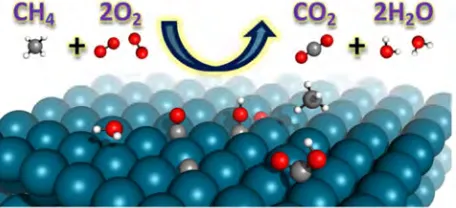
hydrogen adsorption is unity concerning bare surface sites, and the order of carbon monoxide adsorption is second with regard to bare surface sites. Furthermore, methane is assumed to be irreversibly adsorbed. A surface site density is specified to be 2.72 × 10⁻⁹ mol/cm2 for the supported platinum catalyst [46]. The adsorption rate constant kad,k of k-th gaseous species
is modeled using a modified Motz-Wise correction [47]. The detailed homogeneous reaction scheme is based on the Leeds methane oxidation mechanism [48], complemented and corrected by Turányi et al. [49]. The mechanism has been tested against experimental data. Thermodynamic data are taken from the provided schemes, and transport properties are computed using the CHEMKIN transport database [42]. Homogeneous and heterogeneous reaction rates are evaluated with CHEMKIN [50] and Surface-CHEMKIN [51], respectively.
Figure 2. Schematic diagram of the heterogeneous reaction.
2.4. Boundary Conditions
At the inlet, a fixed, flat velocity profile is used. While this boundary condition fixes the convective component of the flux of energy and species, the diffusive component is highly dependent on the gradient of the computed species or temperature fields within the system. At the fluid centerline, symmetry boundary conditions are employed. At the exit, a fixed pressure is specified and far-field conditions are imposed for the rest of the variables. No-slip boundary condition is employed for both velocity components at the gas-wall interface. At the outlet and the symmetry plane, the transverse flow velocity is set to zero and zero-Neumann conditions are employed for all other scalars. The heat flux at the gas-wall interface is computed and continuity in temperature and heat flux links the fluid and solid phases. For the left and right edges of the wall, the heat loss to the surroundings is assumed. Furthermore, all internal heat transfer between the fluid and the wall is computed by accounting explicitly for the convective and conductive heat transfer in the model within the system.
2.5. Computation Scheme
An orthogonal staggered grid is employed. The solid wall is discretized such that the elements at the gas-wall interface have the same axial size as the corresponding elements on the fluid sides. The grid is finer where the gradients in temperature and species concentration are steeper. In order to determine the optimal density as well as node spacing that
would minimize computation time and give the desired accuracy, computations are performed using grids with varying nodal densities. All solutions presented herein are obtained using a grid consisting of 20000 nodes, i.e., 20 transverse nodes within the wall as well as 200 axial nodes by 80 transverse nodes within the fluid. The fluid density is computed using the ideal gas law. The species specific heat is computed using a piecewise polynomial fit of temperature, and the fluid thermal conductivity, specific heat, and viscosity are computed from a mass fraction weighted average of species properties [52]. In order to discretize the model, the second-order upwind scheme is employed. The “SIMPLE” algorithm [53] is employed to solve for the pressure and velocity fields. In order to solve the governing equations, a segregated solution solver is employed, using an under-relaxation method. Generally, convergence is very difficult due to the disparity between the fluid and the wall thermal conductivities as well as the inherent stiffness of the chemistry. Natural parameter continuation is implemented to achieve convergence.
3. Results and Discussion
3.1. Numerical Validation
Figure 3. OH concentration profiles along the fluid centerline after homogeneous ignition.
The numerical model is validated by comparing the results with the experimental data of Dogwiler et al. [54]. Direct comparisons between simulation and experiment allow for an assessment of the model used herein. The methane-air mixtures with the inlet equivalence ratios of φ = 0.37, 0.37, and 0.31 are chosen, corresponding to three catalytic cases further denoted as (A), (B), and (C) of the experimental data, respectively. These catalytic cases with inlet equivalence ratios (φ), inlet velocities (uin), and inlet temperatures (Tin) are
described as follows: case (A), Tin = 750 K, uin = 1.0 m/s, φ =
0.37; case (B), Tin = 729 K, uin = 2.0 m/s, φ = 0.37; and case
(C), Tin = 754 K, uin = 1.0 m/s, φ = 0.31. The Reynolds number
serve as the energy boundary conditions at the gas-wall interface. Figure 3 shows the OH concentration profiles along the fluid centerline after homogeneous ignition. The irregular curves represent the measured OH concentrations, and the dash-color lines represent the predicted OH concentrations. The predicted profiles have been shifted axially to match the measured peak OH positions. The sharp rise in OH concentration along the reactor denotes the onset of homogeneous ignition. Good agreement between predicted and measured profiles is observed, since the difference between them is generally less than 20%. On the other hand,
the measured positions of homogeneous ignition for cases (A), (B), and (C) are 78, 148, and 83 mm, respectively. The predicted positions of homogeneous ignition are 66, 136, and 70 mm, respectively. Good agreement between predicted and measured ignition positions is also achieved, since the difference between them is within 16% in all the cases studied. Overall, the numerical results, such as OH concentration profiles and ignition positions, are in good agreement with the experimental data. This confirms the reasonable accuracy of the numerical model implemented in this study.
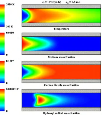
3.2. Contour Plots
Figure 4. Contour plots of the temperature and mass fraction for a typical set of operating parameters.
Figure 4 shows the contour plots of the temperature and mass fraction for a typical set of operating parameters. The entire reactor is presented. Self-sustained combustion can be found within the system. The exothermic reaction starts at the surfaces of the catalyst and travels towards the fluid centerline. Catalytic reaction takes place very rapidly, combusting most of the fuel in a relatively small region. A significant temperature rise is observed due to the exothermicity of the combustion, and complete fuel conversion is obtained.
attributed to the short time-scale for heat conduction across the wall and their large aspect ratio.
3.3. Temperature Profiles
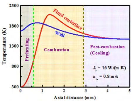
Figure 5. Temperature profiles along the fluid centerline and the wall.
Figure 5 shows the temperature profiles along the fluid centerline and the wall. Three regions can be observed, namely preheating, combustion, and post-combustion or cooling. The width of these regions is highly dependent on operating conditions. In the preheating region, the wall temperature is much higher than that of the fluid, and thus the thermal energy is transferred from the wall to the fluid. The fluid thermal conductivity is significantly lower than that of the wall. Within the walls, therefore, most of the upstream conductive heat transfer occurs. This thermal energy is brought upstream from the post-combustion region in which the wall temperature is considerably high to the cold incoming reactants. Ignition occurs near the catalytic walls and self-sustained combustion can be found at the fluid centerline, as the fluid mixture warms up from the wall towards the fluid centerline. This is consistent with the combustion stability studies carried out in one-dimensional stagnation flows [19, 23]. However, this catalytic ignition mode is quite different from the case in which outside preheating is employed to ignite the gas mixture. When preheating is employed, ignition occurs at the fluid centerline [25, 55].
Once the fluid reaches the ignition temperature in the presence of catalyst, which is approximately 880 K, there is an inflection point in the fluid temperature profile. The reactants are consumed rapidly, releasing heat and then causing a sharp rise in the fluid temperature within the system. This “take-off” point is consistent in temperature with the experimental findings of Dagaut et al. [56]. Due to the upstream heat transfer through the walls to the cold incoming reactants, the wall temperature in the preheating region reaches the ignition temperature of approximately 880 K to allow ignition of the fluid in the combustion region. Self-sustained combustion occurs in a relatively narrow region, which is a characteristic of highly activated reactions. Despite the small scales of these systems, the rate of heat release is much faster than the transverse heat transfer within the fluid so that the fluid
centerline temperature in this region is extremely high, which approaches approximately the adiabatic flame temperature in some cases.
In the post-combustion region, the reaction is completed as the reactants have been consumed. The fluid cools down to the wall temperature, and the walls are cooled by external heat losses. There exist no significant axial or transverse gradients in temperature and species concentration within this region. Both the fluid and the wall would eventually be cooled to the ambient temperature in non-adiabatic cases, if the reactor is sufficiently long. In some cases, the maximum fluid temperature is higher than the adiabatic flame temperature of methane-air mixtures, which is consistent with the flame behavior reported by Gauthier and co-workers [57, 58]. Traditional analysis of plug flow reactor or continuous stirred tank reactor suggests that this is not possible to achieve with detailed chemistry and transport [59, 60]. In this computational fluid dynamics model, however, the walls act as a conduit for upstream heat transfer through the walls from the hot exiting products to the cold incoming reactants. This causes a heat recuperation within the system, resulting in an increase in temperature near the entrance, which allows a maximum temperature that is higher than the adiabatic flame temperature. In these cases, however, the exiting fluid temperature is lower than the adiabatic flame temperature for adiabatic walls, which can be attributed to the overall energy conservation within the system.
3.4. Effect of Wall Thermal Conductivity
Figure 6. Effect of wall thermal conductivity on the flame location.
preheating, the wall thermal conductivity plays an important role in determining the combustion stability of the system [20, 22, 24]. Low wall thermal conductivity inhibits the upstream heat transfer through the wall, and thus the preheating of the feed is limited, inhibiting initialization of the combustion, and causing blowout. Additionally, hot spots of high temperatures within the walls may occur, which could damage the catalyst. In contrast, high thermal conductivity walls result in lower operating temperatures, and the isothermality of the system can be expected. However, high thermal conductivity walls offer a larger hot area for external heat losses and become susceptible to spatially global-like extinction [20, 22]. To quantitatively differentiate between the different regions and monitor the possible blowout behavior, the flame location is defined as the axial position with the greatest reaction rate. The flame location in all cases occurs on the fluid centerline. The flow velocity plays an important role in determining flame location. For high flow velocities, the flame location moves downstream with the increase of flow velocity. This is because of the shorter residence times, i.e., the decrease in the convective time-scales. For low flow velocities, a sharp shift of the reaction region downstream occurs with the decrease of flow velocity. This is because of the decrease in the heat generation rate. The heat generation rate in this case is still much faster than the external heat loss rate, causing a reduced upstream heat-transfer rate. There is a minimum in the location of the flame, which is highly dependent on the wall thermal conductivity, which can be attributed to the competition between decreased residence time and increased volumetric heat released with the increase of flow velocity. This minimum approaches the unconfined flame speed for the same feed composition, experimentally determined by Vagelopoulos and Egolfopoulos [61, 62]. The minimum moves slightly toward higher flow velocities for higher wall thermal conductivities, as the latter allow greater upstream heat transfer to compete with the faster convective flow.
3.5. Effect of Reactor Dimension
Figure 7. Effect of reactor dimension on the flame location.
Figure 7 shows the effect of reactor dimension on the flame location. When the primary variable is the wall thermal
conductivity, the gap distance and wall thickness play an important role in combustion stability also when the flow velocity varies. The blowout velocity decreases with the increase of gap distance. The decrease in combustion stability with respect to flow velocity is mainly because of the reduced time-scales for energy diffusion between the walls and the fluid, which limits the preheating of the feed, and thus shifts the flame location downstream. Conversely, the blowout velocity increases with the increase of wall thickness, while leaving unaffected the combustion stability for slow flows. The increase in combustion stability is mainly because of the increased area for heat flux and upstream preheating rate to the cold incoming reactants. When flow velocities greater than the unconfined flame speed are required, the gap distance must be small, and the wall thickness and thermal conductivity should be sufficiently high to provide effective heat recuperation from the post-combustion region to preheat the cold incoming reactants.
3.6. Stability Diagram
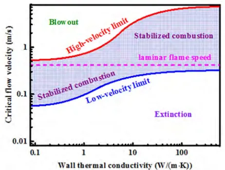
Figure 8. Stability diagram in terms of the critical flow velocity as a function of wall thermal conductivity.
against external heat losses. In contrast, higher wall thermal conductivities cause maximum allowable flow velocities. However, the increased external heat losses prohibit low flow velocities. This relationship becomes significant when designing micro-devices. When a high-power system is desired, highly conductive materials should be preferred. In contrast, when a low-power system is desired, highly insulating materials should be favored to minimize external heat losses. The focus here is on the combustion stability. However, other wall thermal properties, such as mechanical strength, radical sticking, and allowable operating temperatures, along with the system efficiency, must be considered when designing device dimensions and choosing a material for construction.
3.7. Operation Diagram
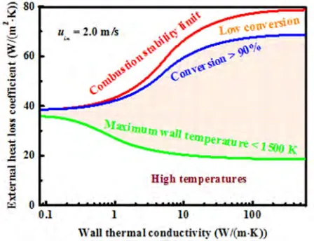
Figure 9. Operation diagram for methane-air catalytic combustion.
Combustion stability is not the only one that determines the choice of reactor design and operating conditions [67, 68]. Low device temperature, in order to ensure material stability, and high conversion are important performance factors. Methane conversion in excess of 90% and a maximum wall temperature of 1500 K are taken as reasonable, albeit arbitrary, thresholds in this study. Generally, both conversion and temperature decrease with increasing external heat loss coefficient. This is the case when the reactor is exposed to lower environmental temperatures or coupled to highly endothermic reactions. In contrast, as the reactor becomes more adiabatic, higher conversion is achieved at the risk of higher temperatures. Figure 9 shows the operation diagram for methane-air catalytic combustion. The red line represents the combustion stability limit, and the blue and green lines represent the contours of 90% conversion and of a maximum wall temperature of 1500 K, respectively. The shaded region between the two curves is the operation region that satisfies both material stability and combustion efficiency criteria. For lower external heat loss coefficients than the lower boundary, temperatures become too high. In contrast, for higher external heat loss coefficients than the upper boundary, conversion drops. The operation region is very narrow at low wall conductivities and expands significantly for moderate and
high wall conductivities. Obviously, these boundaries can be manipulated for each material by, for example, changing equivalence ratio and residence time. While these maps clearly pertain to the specific fuels and to parallel plate configurations of fixed dimensions, the approach employed herein is general and similar findings are expected for other micro-chemical systems.
4. Conclusions
The combustion characteristics of methane-air mixtures in catalytic microreactors are studied using a two-dimensional computational fluid dynamics model. It is shown that the catalytic combustion of methane-air mixtures can be stabilized at small scales but very careful design is necessary. Despite the small characteristic length scales of these systems, large axial gradients in temperature may exist in the walls as well as large transverse gradients in temperature and species concentration exist in the fluid. The wall thickness and thermal conductivity are important parameters in design, since they strongly affect the combustion characteristics. The flow velocity plays a competing role in combustion stability. Low flow velocities reduce the power generation. In contrast, high flow velocities reduce the convective time-scale below that of the upstream heat transfer through the walls. Consequently, there exists only a relatively narrow regime of flow velocities within which self-sustained operation is allowed. A high-power system would favor highly conductive materials. In contrast, when a low-power system is being designed, highly insulating materials should be favored to minimize external heat losses. However, other wall thermal properties and the system efficiency must be considered in design. Engineering maps are constructed to gain insight into the energy management at small scales.
Acknowledgements
This work was supported by the National Natural Science Foundation of China (No. 51506048).
References
[1] A. C. Fernandez-Pello. Micropower generation using combustion: Issues and approaches. Proceedings of the Combustion Institute, Volume 29, Issue 1, 2002, Pages 883-899.
[2] N. S. Kaisare and D. G. Vlachos. A review on microcombustion: Fundamentals, devices and applications. Progress in Energy and Combustion Science, Volume 38, Issue 3, June 2012, Pages 321-359.
[3] D. C. Walther and J. Ahn. Advances and challenges in the development of power-generation systems at small scales. Progress in Energy and Combustion Science, Volume 37, Issue 5, 2011, Pages 583-610.
[5] S. K. Chou, W. M. Yang, K. J. Chua, J. Li, and K. L. Zhang. Development of micro power generators - A review. Applied Energy, Volume 88, Issue 1, 2011, Pages 1-16.
[6] V. Shirsat and A. K. Gupta. A review of progress in heat recirculating meso-scale combustors. Applied Energy, Volume 88, Issue 12, 2011, Pages 4294-4309.
[7] F. A. Robbins, H. Zhu, and G. S. Jackson. Transient modeling of combined catalytic combustion/CH4 steam reforming.
Catalysis Today, Volume 83, Issues 1-4, 2003, Pages 141-156.
[8] M. Mundhwa and C. P. Thurgood. Numerical study of methane steam reforming and methane combustion over the segmented and continuously coated layers of catalysts in a plate reactor. Fuel Processing Technology, Volume 158, 2017, Pages 57-72.
[9] S. W. Jeon, W. J. Yoon, M. W. Jeong, and Y. Kim. Optimization of a counter-flow microchannel reactor using hydrogen assisted catalytic combustion for steam reforming of methane. International Journal of Hydrogen Energy, Volume 39, Issue 12, 2014, Pages 6470-6478.
[10] M. Zanfir and A. Gavriilidis. Catalytic combustion assisted methane steam reforming in a catalytic plate reactor. Chemical Engineering Science, Volume 58, Issue 17, 2003, Pages 3947-3960.
[11] Z. R. Ismagilov, O. Yu. Podyacheva, V. V. Pushkarev, N. A. Koryabkina, V. N. Antsiferov, Y. V. Danchenko, O. P. Solonenko, and H. Veringa. Development and study of metal foam heat-exchanging tubular reactor: Catalytic combustion of methane combined with methane steam reforming. Studies in Surface Science and Catalysis, Volume 130, 2000, Pages 2759-2764.
[12] C. Cao, N. Zhang, X. Chen, and Y. Cheng. A comparative study of Rh and Ni coated microchannel reactor for steam methane reforming using CFD with detailed chemistry. Chemical Engineering Science, Volume 137, 2015, Pages 276-286.
[13] V. R. Regatte and N. S. Kaisare. Hydrogen generation in spatially coupled cross-flow microreactors. Chemical Engineering Journal, Volumes 215-216, 2013, Pages 876-885.
[14] N. S. Kaisare, G. D. Stefanidis, and D. G. Vlachos. Millisecond production of hydrogen from alternative, high hydrogen density fuels in a cocurrent multifunctional microreactor. Industrial & Engineering Chemistry Research, Volumes 48, Issue 4, 2009, Pages 1749-1760.
[15] P. Aghalayam and D. G. Vlachos. Roles of thermal and radical quenching in emissions of wall-stabilized hydrogen flames. AIChE Journal, Volume 44, Issue 9, 1998, Pages 2025-2034.
[16] H. Nakamura and S. Hasegawa. Combustion and ignition characteristics of ammonia/air mixtures in a micro flow reactor with a controlled temperature profile. Proceedings of the Combustion Institute, Volume 36, Issue 3, 2017, Pages 4217-4226.
[17] J. Wan, A. Fan, H. Yao, and W. Liu. Experimental investigation and numerical analysis on the blow-off limits of premixed CH4/air flames in a mesoscale bluff-body combustor. Energy,
Volume 113, 2016, Pages 193-203.
[18] J. Wan, A. Fan, Y. Liu, H. Yao, W. Liu, X. Gou, and D. Zhao. Experimental investigation and numerical analysis on flame stabilization of CH4/air mixture in a mesoscale channel with
wall cavities. Combustion and Flame, Volume 162, Issue 4, 2015, Pages 1035-1045.
[19] D. G. Vlachos, L. D. Schmidt, and R. Aris. Ignition and extinction of flames near surfaces: Combustion of CH4 in air.
AIChE Journal, Volume 40, Issue 6, 1994, Pages 1005-1017.
[20] D. G. Norton and D. G. Vlachos. Combustion characteristics and flame stability at the microscale: a CFD study of premixed methane/air mixtures. Chemical Engineering Science, Volume 58, Issue 21, 2003, Pages 4871-4882.
[21] P. Aghalayam, P.-A. Bui, and D. G. Vlachos. The role of radical wall quenching in flame stability and wall heat flux: hydrogen-air mixtures. Combustion Theory and Modelling, Volume 2, Issue 4, 1998, Pages 515-530.
[22] D. G. Norton and D. G. Vlachos. A CFD study of propane/air microflame stability. Combustion and Flame, Volume 138, Issues 1-2, 2004, Pages 97-107.
[23] D. G. Vlachos, L. D. Schmidt, and R. Aris. Ignition and extinction of flames near surfaces: Combustion of H2 in air.
Combustion and Flame, Volume 95, Issue 3, 1993, Pages 313-335.
[24] N. S. Kaisare and D. G. Vlachos. Optimal reactor dimensions for homogeneous combustion in small channels. Catalysis Today, Volume 120, Issue 1, 2007, Pages 96-106.
[25] S. Raimondeau, D. Norton, D. G. Vlachos, and R. I. Masel. Modeling of high-temperature microburners. Proceedings of the Combustion Institute, Volume 29, Issue 1, 2002, Pages 901-907.
[26] J. Wan, A. Fan, and H. Yao. Effect of the length of a plate flame holder on flame blowout limit in a micro-combustor with preheating channels. Combustion and Flame, Volume 170, 2016, Pages 53-62.
[27] A. Fan, J. Wan, Y. Liu, B. Pi, H. Yao, and W. Liu. Effect of bluff body shape on the blow-off limit of hydrogen/air flame in a planar micro-combustor. Applied Thermal Engineering, Volume 62, Issue 1, 2014, Pages 13-19.
[28] K. Maruta, K. Takeda, J. Ahn, K. Borer, L. Sitzki, P. D. Ronney, and O. Deutschmann. Extinction limits of catalytic combustion in microchannels. Proceedings of the Combustion Institute, Volume 29, Issue 1, 2002, Pages 957-963.
[29] J. Ahn, C. Eastwood, L. Sitzki, and P. D. Ronney. Gas-phase and catalytic combustion in heat-recirculating burners. Proceedings of the Combustion Institute, Volume 30, Issue 2, 2005, Pages 2463-2472.
[30] R. Sui and J. Mantzaras. Combustion stability and hetero-/homogeneous chemistry interactions for fuel-lean hydrogen/air mixtures in platinum-coated microchannels. Combustion and Flame, Volume 173, 2016, Pages 370-386.
[31] C.-H. Leu, S.-C. King, J.-M. Huang, C.-C. Chen, S.-S. Tzeng, C.-I. Lee, W.-C. Chang, and C.-C. Yang. Visible images of the catalytic combustion of methanol in a micro-channel reactor. Chemical Engineering Journal, Volume 226, 2013, Pages 201-208.
[33] V. Balakotaiah, I. Alam, and D. H. West. Heat and mass transfer coefficients and bifurcation analysis of coupled homogeneous-catalytic reactions. Chemical Engineering Journal, Volume 321, 2017, Pages 207-221.
[34] S. A. Smyth and D. C. Kyritsis. Experimental determination of the structure of catalytic micro-combustion flows over small-scale flat plates for methane and propane fuel. Combustion and Flame, Volume 159, Issue 2, 2012, Pages 802-816.
[35] J. Badra, A. R. Masri, C. Zhou, and B. S. Haynes. An experimental and numerical study of surface chemical interactions in the combustion of propylene over platinum. Combustion and Flame, Volume 160, Issue 2, 2013, Pages 473-485.
[36] L. D. Pfefferle and W. C. Pfefferle. Catalysis in combustion. Catalysis Reviews: Science and Engineering, Volume 29, Issue 2-3, 1987, Pages 219-267.
[37] D. Ciuparu, M. R. Lyubovsky, E. Altman, L. D. Pfefferle, and A. Datye. Catalytic combustion of methane over palladium-based catalysts. Catalysis Reviews: Science and Engineering, Volume 44, Issue 4, 2002, Pages 593-649.
[38] G. Kolb and V. Hessel. Micro-structured reactors for gas phase reactions. Chemical Engineering Journal, Volume 98, Issues 1-2, 2004, Pages 1-38.
[39] L. Kiwi-Minsker and A. Renken. Microstructured reactors for catalytic reactions. Catalysis Today, Volume 110, Issues 1-2, 2005, Pages 2-14.
[40] A. C. Eckbreth. Laser Diagnostics for Combustion Temperature and Species, 2nd Edition, CRC Press, Boca Raton, United States, 1996.
[41] J. Jarosinski and B. Veyssiere. Combustion Phenomena: Selected Mechanisms of Flame Formation, Propagation and Extinction, CRC Press, Boca Raton, United States, 2017.
[42] R. J. Kee, G. Dixon-lewis, J. Warnatz, M. E. Coltrin, J. A. Miller, and H. K. Moffat. A Fortran computer code package for the evaluation of gas-phase, multicomponent transport properties, Report No. SAND86-8246B, Sandia National Laboratories, 1998.
[43] J. R. Howell, M. P. Menguc, and R. Siegel. Thermal Radiation Heat Transfer, 6th Edition, CRC Press, Boca Raton, United States, 2015.
[44] K. Stamnes, S.-C. Tsay, W. Wiscombe, and K. Jayaweera. Numerically stable algorithm for discrete-ordinate-method radiative transfer in multiple scattering and emitting layered media. Applied Optics, Volume 27, Issue 12, 1988, Pages 2502-2509.
[45] T. L. Bergman, A. S. Lavine, F. P. Incropera, and D. P. DeWitt. Fundamentals of Heat and Mass Transfer, 8th Edition, John Wiley & Sons, Inc., Hoboken, United States, 2017.
[46] O. Deutschmann, L. I. Maier, U. Riedel, A. H. Stroemman, and R. W. Dibble. Hydrogen assisted catalytic combustion of methane on platinum. Catalysis Today, Volume 59, Issues 1-2, 2000, Pages 141-150.
[47] U. Dogwiler, P. Benz, and J. Mantzaras. Two-dimensional modelling for catalytically stabilized combustion of a lean methane-air mixture with elementary homogeneous and heterogeneous chemical reactions. Combustion and Flame, Volume 116, Issues 1-2, 1999, Pages 243-258.
[48] K. J. Hughes, T. Turányi, A. R. Clague, M. J. Pilling. Development and testing of a comprehensive chemical mechanism for the oxidation of methane. International Journal of Chemical Kinetics, Volume 33, Issue 9, 2001, Pages 513-538.
[49] T. Turányi, L. Zalotai, S. Dóbé, T. Bérces. Effect of the uncertainty of kinetic and thermodynamic data on methane flame simulation results. Physical Chemistry Chemical Physics, Volume 4, Issue 12, 2002, Pages 2568-2578.
[50] R. J. Kee, F. M. Rupley, E. Meeks, and J. A. Miller. CHEMKIN-III: a Fortran chemical kinetics package for the analysis of gasphase chemical and plasma kinetics, Report No. SAND96-8216, Sandia National Laboratories, 1996.
[51] M. E. Coltrin, R. J. Kee, F. M. Rupley, and E. Meeks. SURFACE CHEMKIN-III: a Fortran package for analyzing heterogeneous chemical kinetics at a solid-surface-gas-phase interface, Report No. SAND96-8217, Sandia National Laboratories, 1996.
[52] R. B. Bird, W. E. Stewart, and E. N. Lightfoot. Transport Phenomena, Revised 2nd Edition, John Wiley & Sons, Inc., Hoboken, United States, 2007.
[53] S. V. Patankar and D. B. Spalding. A calculation procedure for heat, mass and momentum transfer in three-dimensional parabolic flows. International Journal of Heat and Mass Transfer, Volume 15, Issue 10, 1972, Pages 1787-1806.
[54] U. Dogwiler, J. Mantzaras, P. Benz, B. Kaeppeli, R. Bombach, and A. Arnold. Homogeneous ignition of methane-air mixtures over platinum: Comparison of measurements and detailed numerical predictions. Symposium (International) on Combustion, Volume 27, Issue 2, 1998, Pages 2275-2282.
[55] J. Daou and M. Matalon. Influence of conductive heat-losses on the propagation of premixed flames in channels. Combustion and Flame, Volume 128, Issue 4, 2002, Pages 321-339.
[56] P. Dagaut, J. C. Boettner, and M. Cathonnet. Methane oxidation: Experimental and kinetic modeling study. Combustion Science and Technology, Volume 77, Issue 1-3, 1991, Pages 127-148.
[57] G. P. Gauthier, G. M. G. Watson, and J. M. Bergthorson. Burning rates and temperatures of flames in excess-enthalpy burners: A numerical study of flame propagation in small heat-recirculating tubes. Combustion and Flame, Volume 161, Issue 9, 2014, Pages 2348-2360.
[58] G. P. Gauthier and J. M. Bergthorson. Effect of external heat loss on the propagation and quenching of flames in small heat-recirculating tubes. Combustion and Flame, Volume 173, 2016, Pages 27-38.
[59] P. G. Lignola and F. P. D. Maio. Some remarks on modeling CSTR combustion processes. Combustion and Flame, Volume 80, Issues 3-4, 1990, Pages 256-263.
[60] F. Sen, B. Shu, T. Kasper, J. Herzler, O. Welz, M. Fikri, B. Atakan, and C. Schulz. Shock-tube and plug-flow reactor study of the oxidation of fuel-rich CH4/O2 mixtures enhanced with
additives. Combustion and Flame, Volume 169, 2016, Pages 307-320.
[62] C. M. Vagelopoulos and F. N. Egolfopoulos. Direct experimental determination of laminar flame speeds. Symposium (International) on Combustion, Volume 27, Issue 1, 1998, Pages 513-519.
[63] K. K. Kuo. Principles of Combustion, 2nd Edition, John Wiley & Sons, Inc., Hoboken, United States, 2005.
[64] P. Clavin. Dynamic behavior of premixed flame fronts in laminar and turbulent flows. Progress in Energy and Combustion Science, Volume 11, Issue 1, 1985, Pages 1-59.
[65] V. Raghavan. Combustion Technology: Essentials of Flames and Burners, John Wiley & Sons, Inc., Hoboken, United States, 2016.
[66] C. K. Law and C. J. Sung. Structure, aerodynamics, and geometry of premixed flamelets. Progress in Energy and Combustion Science, Volume 26, Issues 4-6, 2000, Pages 459-505.
[67] S. R. Deshmukh and D. G. Vlachos. Effect of flow configuration on the operation of coupled combustor/reformer microdevices for hydrogen production. Chemical Engineering Science, Volume 60, Issue 21, 2005, Pages 5718-5728.