Optimization of Intraocular Capacitive Pressure Sensor
N. Saad1,* and N. Soin2
1School of Mechatronic Engineering, Universiti Malaysia Perlis (UniMAP), Perlis, Malaysia. 2Department of Electrical Engineering, Faculty of Engineering, University of Malaya, Kuala Lumpur,
Malaysia.
ABSTRACT
Intraocular MEMS capacitive pressure sensors are useful for measuring intraocular pressure (IOP) for Glaucoma patients. For normal person, IOP reading range within 10-21mmHg. For IOP applications, compatible biomedical sensors are required to operate in the range of 0-8 kPa (0-60mmHg). Intraocular MEMS capacitive pressure sensors are widely used in IOP measurement because it provides higher sensitivity to pressure, low noise, low temperature sensitivity and micro in size. In this research project, a corrugated MEMS capacitive pressure sensor is designed and demonstrated using COMSOL Multiphysics software. Result obtained from the simulation is the deflection of the corrugated diaphragm when 8kPa pressure is applied. From the diaphragm deflection, sensors mechanical sensitivity, capacitance sensitivity and residual stress varies with the pressure applied. When corrugation depth is increased, maximum deflection will decrease, hence the capacitance value is increased respectively. Capacitance sensitivity for corrugation depth, H=32 µm is obtained at 6.8451x10⁻³ fF/Pa which is 0.684% higher than flat diaphragm’s capacitance sensitivity. From the simulation, it is proven that residual stress for corrugated diaphragm is 63.147 MPa which is lower than flat diaphragms residual stress. The optimized parameter for corrugation depth is at H=45 µm which has higher capacitance sensitivity and smallest residual stress.
Keywords: MEMS Capacitive Pressure Sensor, Sensitivity, Slot Diaphragm, Corrugated Diaphragm, Intraocular Pressure.
1. INTRODUCTION
Glaucoma is fourth major effects that cause blindness in Malaysia [1]. Specifically, glaucoma is a blindness cause by damaged optic nerve which failed to transmit image to the brain. The damaged on the optic nerve is caused by the increased pressure inside the eye called intraocular pressure (IOP). IOP is the fluid pressure inside the eye. The increase in pressure is attributed to the build up of ocular fluid, the aqueous humor, in the anterior chamber of the eye. The increase in pressure can cause damage to the optic nerve tissue, loss of peripheral vision, and ultimately blindness [2].
There is a variety of possible devices that can be surgically implanted into the eye to treat elevated IOP. IOP is measured in millimeters of mercury (mmHg). Normal IOP should be within 10 - 20 mmHg [3]. Most important part of IOP measurement is the sensor design and sensitivity. Excellent sensor with higher sensitivity to pressure will lead to an accurate intraocular pressure measurement [4][5].
Sensing mechanism in a pressure sensor regularly uses parallel plate capacitor principle. A capacitive pressure sensor consists of two parallel diaphragms (top and bottom electrodes) distant by air gap (vacuum or any dielectric material) and pressure cavity to create a variable
capacitor due to applied pressure. The change in capacitance is used to detect strain on top diaphragm while the bottom electrode is fixed [3]. Diaphragm shape itself can be design in many forms such as circle, square, rectangular, square with slotted and many more. But each of the shape has their own advantages and disadvantages depend on their application. Circle and square diaphragms are most widely studied by the researchers and engineers. For example [6] design and simulated two shapes of diaphragm for intraocular measurement and they found out that square diaphragm gives optimum output compared to circle diaphragm. While further studies discover that central deflection of square slotted diaphragm a more than clamped diaphragm for the same pressure given [7]. Among all diaphragm shapes, circular diaphragms are the best in deflection effects while square diaphragm benefits more during manufacturing process because it can easily be slicing from standards wafer to a square shape [16].
Generally, thin-film diaphragms suffer from residual stresses when pressure is applied. Residual stress usually influenced the structure mechanical behaviour. Effects of high residual stress such as film buckling, high voltage actuation and undesirable diaphragm cracking [8]. To overcome all the effects of residual stress in flat diaphragm, corrugated diaphragm technique is always the best alternative. The corrugations techniques reduce the effects of the residual stress, increase the diaphragm linear range and mechanical sensitivity [9].
In this paper, a few corrugation depths had been modelled to achieve higher sensitivity and lower residual stress in a corrugated diaphragm for a capacitive pressure sensor for IOP monitoring purpose. Specifically, the objectives of this paper are to design corrugated MEMS diaphragm and to achieve capacitance, C more than 53.5921 fF, capacitance sensitivity, Sc higher
than 6.69901x10⁻³fF/Pa and to obtain optimal structure parameter of MEMS diaphragm in intraocular measurement.
2. CAPACITIVE PRESSURE SENSOR DESIGN
2.1 Basic Design
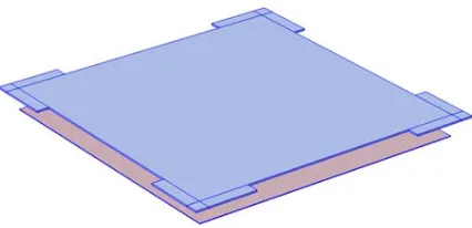
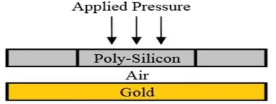
MEMS intraocular capacitive pressure sensor is designed based on research paper with title Optimization of Intraocular MEMS Capacitive Pressure Sensor by Muslihah Ali [10]. The structure is a square four slotted diaphragm and a gold square plate for bottom diaphragm shows in Fig. 1. While air gap is used in between the plate shows in Fig. 2. The sensor size is set at 550 µm X 550 µm X 4.2 µm for upper plate and 550 µm X 550 µm X 2 µm for bottom plate and a 50 µm air gap in between the plate. While slot size is set at 100 µm X 25 µm X 4.2 µm (length, width and thickness) for optimum performance. IOP for normal person without Glaucoma is around 0-21 mmHg and for glaucoma person IOP can goes up to 60 mmHg. So, applied pressure used for this research ranging from 0 to 60 mmHg (8 KPa).
Figure 2. Cross sectional view of IOP capacitive pressure sensor.
Poly silicon is used as a material for upper plate and for bottom plate, gold material is used. The Young’s Modulus and Poisson’s ratio of poly silicon are 169 GPa and 0.22 respectively. While initial stress, σ is assumed to be 70 MPa [11].
Deformation of the top electrode due to applied pressure will be translated into an electrical capacitance change. Capacitance value will vary when pressure is applied and distances between the electrodes also changes accordingly as in (1).
(1)
Where C is Capacitance, ε0 is permittivity of free space (8.854×10⁻¹⁴ F/cm), εris relative dielectric constant of material between the electrodes (unity for air), A is effective diaphragm area and d
is distance between the electrodes respectively.
2.2 Corrugated Diaphragm Design Parameters
For this project, a corrugated diaphragm is designed based on the dimension mentioned in part II (A) for the optimization purpose. Important parameter for a corrugated diaphragm analysis arecorrugation depth, H, diaphragm thickness, h and pitch of corrugation, l. But the most effective parameter that influence the behaviour of corrugated diaphragms is the corrugation depth, H [12]. Behaviour of corrugated diaphragm is determined by a corrugation quality factor
q [12]. First step in designing corrugated diaphragm is to calculate the q value from the diaphragm thickness, h by choosing suitable corrugation depth, H. For a standard diaphragm, q
can be determined using (2).
(2)
Where s is the corrugation arc length, l is the corrugation pitch and H is corrugation depth and h
is diaphragm thickness. Value of q normally lies within the range from 5 up to 15. The higher the value of q will show a higher rigidity of the diaphragm with a longer linear length. If q is too small, corrugated diaphragm shows performance equal to flat diaphragm performance which has a unity value for q [13].
For a rectangular shape corrugation distributed over a whole area of square diaphragm, approximate mechanical sensitivity, Sm(square) can be obtained using (3) [9] .
(3)
Where h is thickness, 2a is the side length of the diaphragm, E is the Young’s Modulus, σ is initial stress of the diaphragm without corrugation and the value of Ap and Bp can be determined [14]
(4)
(
-
)
(5)
Center deflection, W0 of corrugated square diaphragm with clamped edges can be obtained from
(6) respectively [14].
(6)
While capacitance sensitivity, Sc of capacitive pressure sensor is obtained from (7) respectively
[6].
S
c(7)
Where ΔC is change in capacitance of the parallel plates, C0 is initial capacitance when pressure
is zero and ΔP is change in load pressure.
2.3 Corrugated Diaphragm Optimization
Figure 3 shows the three-dimensional (3D) axis-model symmetrical geometry of corrugated capacitive pressure sensor build using COMSOL Multiphysics Software. Blue colour surface represent poly silicon material, while yellow colour surface is a gold material. Figure 4 shows the cross sectional view and dimension for the top diaphragm with corrugation depth at 18 µm.
Figure 3. Corrugated capacitive pressure sensor with N=1.
Figure 4. Cross sectional view for corrugation depth, H=18µm.
diaphragm is determined by q value which is normally 5<q<15. For H=10 µm value of q is less than 5 and for H=49 µm value of q larger than 15. Small value of q will result in performance similar as flat diaphragm [13], therefore H=10 µm is selected for q<5. When corrugation depths,
H is increased, the mechanical sensitivity will decrease respectively [14], therefore H=49 µm is chosen for q>15 since the air gap is 50 µm.
Table 1 Different value of H and quality factor, Q value.
H (µm) q
10 3.1929
18 5.6822
32 10.4197
45 15.1618
49 16.6820
3. RESULTS AND DISCUSSIONS
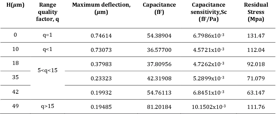
Overall performance of corrugated capacitive pressure sensor is summarized in Table 2. Performances criteria for the sensor are maximum diaphragm deflection, capacitance value, mechanical sensitivity and capacitive sensitivity for corrugation number, N=1.
Table 2 Summary of corrugated diaphragm corrugated sensor performance
H(µm) Range quality factor, q
Maximum deflection,
(µm) Capacitance (fF) sensitivity,Sc Capacitance (fF/Pa)
Residual Stress (Mpa)
0 q=1 0.74614 54.38904 6.7986x10⁻³ 131.47
10 q<1 0.73073 36.57700 4.5721x10⁻³ 112.04
18
5<q<15 0.37983 37.80956 4.7262x10
-3 92.018
35 0.23323 42.31908 5.2899x10⁻³ 71.079
42 0.19932 54.76113 6.8451x10⁻³ 63.147
49 q>15 0.19485 81.20184 10.1502x10⁻³ 111.76
From Table II, highest deflection is when the corrugation depth is H=10 µm. When the corrugation depth is increased, the deflection will decrease respectively. Highest deflection on the corrugated diaphragm is when H=10 µm and range of quality factor, q<5. The deflection difference between flat diaphragm and H=10 µm is around 2.07%. When corrugation depth is increased more than 30 µm, the deflection trend shows only a slight increment between each other.
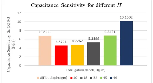
is larger than capacitance sensitivity of the flat diaphragm as in Table II. Capacitance value for
H=32 µm is 54.76113 fF which is higher than capacitance value for flat diaphragm as in Fig 5. Two corrugation depths, H=32 µm and H=49 µm satisfy the objective of this project which is to achieve the capacitance larger than 53.5921 fF. The capacitance is non-linear function since it varies inverse proportional with the diaphragm deflection [11]. Refer to (1), capacitance is determined by a few factors such as effective area, A of the diaphragm and distance between plate, d. When the deflection is reduced, capacitance value will increase [15]. Corrugation profiles also contribute to the larger effective area of the diaphragm in order to increase the capacitance value as mentioned in a paper by Bahram and Burhanuddin [14].
Overall mechanical sensitivity, Sm obtained is lower than flat diaphragm’s mechanical sensitivity.
When the corrugation depth increased, mechanical sensitivity reduced gradually. Mechanical sensitivity is higher for small corrugation depths compared to relatively large corrugation depths for corrugated diaphragm with initial stress [11]. When H=10 µm, the mechanical sensitivity difference with the flat diaphragm is only 4.03% less. This value agrees with the theory mentioned in [11]. When the corrugation depths H>30 µm, mechanical sensitivity reduced more than 50% from flat diaphragm’s mechanical sensitivity. For large corrugation depths, mechanical sensitivity decreased due to the stiffening effects of the corrugations [12].Highest mechanical sensitivity achieved is 9.5175x10⁻⁵fF/Pa when H=10 µm and value for mechanical sensitivity changes slightly in between corrugation depths 32 µm to 49 µm.
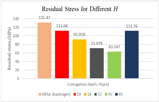
From the simulation result, residual stress in a flat diaphragm is larger than corrugated diaphragm. Highest residual stress is achieved at H=10 µm at 112.74 MPa, but this value still lower than 131.47 MPa. Fig. 6 shows the residual stress obtained during simulation for the different corrugation depths. Introduction of corrugation profiles will reduce the internal stress on a thin film [8]. The smallest residual stress obtained at H=45 µm which range of q=15.1618. Residual stress at H=32 µm is 71.079 MPa which is near to initial stress, σ used for calculation in (3) and (6). Since the mechanical sensitivity is much affected by the initial stress [12], corrugated depths is suitable at H>32 µm. For other corrugation depths, residual stress reduced gradually except at H=49 µm.
Figure 6. Residual stress of the diaphragm for different corrugation depth, H.
4.0 CONCLUSIONS
A corrugated diaphragm for IOP capacitive pressure sensor has been designed and simulated using COMSOL Multiphysics software. For the conclusion, corrugated MEMS capacitive pressure sensor for IOP monitoring had been successfully design and simulated when capacitance value for H=45 µm (q=15.1618), 54.76113 fF is larger than target capacitance value 53.5921 fF. Smallest residual stress, 63.147 MPa is obtained at H=45 µm (q=15.1618). The optimize parameter is achieved at H=45 µm which is higher in capacitance sensitivity and lowest residual stress.
REFERENCES
[1] S. Selvarajah, F. Medicine & H. U. Kebangsaan, “An Analysis of Glaucoma Patients seen at the General Hospital Kuala Lumpur over a Five Year Period : 1986 to 1990” 53, 1 (1998) 42–45.
[2] M. Goel, R. G. Picciani, R. K. Lee & S. K. Bhattacharya, “Aqueous Humor Dynamics : A Review” (2010) 52–59.
[3] K. Ibrahim, “Optimum Design of a Capacitive Pressure Sensor” (2016) 1685–1688.
[4] H. Search, C. Journals, A. Contact, M. Iopscience, S. Mater & I. P. Address, “Micromachined pressure sensors : review and recent developments,” Smart Mater. Struct., 6 (1997) 530– 539.
[5] L. Yu, B. J. Kim & E. Meng, “Chronically Implanted Pressure Sensors: Challenges and State of the Field” (2014) 20620–20644.
[6] Y. M. A. Latha & G. Khanna, “Design and simulative analysis of a batteryless Teflon coated capacitive pressure sensor for glaucoma diagnosis,” 19th Int. Symp. VLSI Des. Test, VDAT 2015 - Proc. (2015) 1–5.
[7] M. Shahiri-Tabarestani, B. a. Ganji & R. Sabbaghi-Nadooshan, “Design and simulation of new micro-electromechanical pressure sensor for measuring intraocular pressure,” 2012 16th IEEE Mediterr.Electrotech.Conf. (2012) 208–211.
[8] A. G. B, “Accurate Model of Capacitance for MEMS Sensors using Corrugated Diaphragm with Residual Stress” 27, 1 (2014) 63–68.
[9] Z. Li, “Design and Fabrication of Silicon Condenser Microphone Using Corrugated Diaphram Technique” 5, 3 (1996) 197–204.
[11] N. Soin & B. Y. Majlis, “An analytical study on diaphragm behavior for micro-machined capacitive pressure sensor,” ICONIP ’02.Proc. 9th Int. Conf. Neural Inf. Process.Comput.Intell. E-Age (IEEE Cat. No.02EX575), (2002) 505–510.
[12] W. Olthuis & P. Bergveld, “The Design, Fabrication, and Testing of Corrugated Silicon Nitride Diaphragms,” J. Microelectromechanical Syst. 3, 1 (1994)36–42.
[13] N. Soin & B. Y. Majlis, “Development of perfect silicon corrugated diaphragm using anisotropic etching,” Microelectron. Eng.83( 4–9 SPEC. ISS.,) (2006) 1438–1441.
[14] B. A. Ganji & B. Y. Majlis, “Modeling of Diaphragms for Micromachined Condenser Microphones B-32” 0(c) (2004) 15–21.
[15] L. Abdelghant, M. N. Maamar, A. Bouguenna & A. Kichene, “Pressure Sensor for biomedical Applications” (2014) 263–266.