23
Design of Reconfigurable Nonuniform Digital Filter
Banks based on Coefficient Decimation Method_Review
Ibtihaj H. Qadoori
University of Baghdad,
College of Engineering, Department of Electrical
Engineering
Mahmood A. K. Abdulsattar
University of Baghdad,
College of Engineering, Department of Electrical
Engineering
ABSTRACT
With the technologies of wireless communication like cognitive radio (CR), analysis filter banks (FBs) are used to adopt two crucial tasks; channelization followed by spectrum sensing. The channelizer is used to obtain separate channels from the wideband digital input signal at different intervals of time. The three main requirements in the channelizer are reconfigurability, low complexity and flexibility. The coefficient decimation technique for reconfigurable FIR filters was recently discussed as a filter structure with low computational complexity. In this brief, the most important types of FBs based on Coefficient Decimation Method (CDM) that used in a nonuniform channelization with comparison among them based on their multiplication complexities and their flexibilities, are discussed.
General Terms
Digital Signal Processing, Finite Impulse Response Filters.
Keywords
Filter banks, Coefficient decimation method, Low Complexity, Flexibility, reconfigurability.
1.
INTRODUCTION
Finite impulse response; (FIR) filters; and Filter; Banks (FBs);
are commonly; performed in digital signal processing; and are favored over their; infinite impulse; response equivalents;
because of their intrinsic phase linearity and stability features. Filter banks are basically divided into analysis banks and synthesis banks [1]. The analysis part of 𝑀-channel FB consists of analysis filters that separate the input signal into M
subband signals. Likewise, the synthesis part of M-channel FB contains M synthesis filters that combine M signals forming a reconstructed signal. Analysis FBs are used in the base station receivers of wireless communication for channelization intentions to extract the frequency channels from wideband input signal [2]. Analysis FBs are performed in cognitive radios to adapt channelization, and spectrum sensing, to detect the radio channels existence or absence [3], [4]. In the applications of resource constrained like battery-powered handsets of mobile Cognitive radio (CR), implementation of low complexity FB is preferred to certify efficient utilization of an inadequate available resources [2]. Many methods were proposed in literature to design and implement reconfigurable filter banks. In [1] the Discrete; Fourier Transform; Filter Bank (DFTFB) is performed as analysis uniform channelization FB. It contains prototype LowPass (LP) filter in polyphase form. The desired bands are obtained using the operation of Inverse DFT; (IDFT). DFTFB is not capable of extracting different bandwidths channels (nonuniform channels) since they considered modulated FBs of equal bandwidth similar to that of the prototype LP filter. In [5], a
Coefficient; Decimation Method; (CDM) was proposed to achieve reconfigurable low complexity FIR filters. This method is capable of generating variable frequency; responses using fixed coefficients of filter by applying two operations of coefficient decimation, the first used to vary the prototype filter passband width (abbreviated as CDM-II), the second used to generate multi-channel frequency responses (abbreviated as CDM-I). In [6], a Filter Bank based Multi-Stage; Coefficient Decimation; (MS-CDFB) was proposed that can offer a changeable sensing resolution in cognitive radios; spectrum sensing. The MS-CDFB multiplication complexity is one-seventh that of DFTFB. The estimated power spectrum accuracy of the MS-CDFB sensor; is better;
2.
REVISION TO COEFFICIENT
DECIMATION METHODS
The coefficient decimation method is used to obtain sub channels from the wideband digital input signal with reduced complexity by a factor of (1/𝑀), where 𝑀 is the decimation factor.
2.1
Coefficient Decimation Method I
(CDM-I)
If each Mth coefficient of an FIR filter is unaltered and the others are set to zeros [5], a frequency response like upsampling images is obtained and this process is named a coefficient decimation method I by a decimation factor of 𝑀 and abbreviated by CDM-I. The resulting filter frequency response expression is
𝐻′ 𝑒𝑗𝑤 = 1
𝑀 𝐻 𝑒 𝑗 𝜔 −2𝜋𝑘𝑀
1 𝑀−1
𝑘=0
From (1), it can be observed that, the resulting M scaled frequency spectrum copies are presented at multiples of (2𝜋/M). After scaling the filter output by M, the original signal can be recovered.
2.2
Coefficient Decimation Method II
(CDM-II)
After applying CDM-I by M factor, the resultant filter reserved coefficients can be gathered by removing in between zeros, the resultant lowpass response that has TBW M times the modal filter's TBW can be found. This process is abbreviated as CDM-II [12]. After performing the CDM-II, a lowpass response with passband width 𝑀 times the base passband width is achieved.
2.3
Modified Coefficient Decimation
Method I (MCDM-I)
Now if each Mth coefficient of FIR filter is unaltered and the sign of each alternate unaltered coefficient is inverted. The rest coefficients are substituted by zeros [8]. The resultant FIR filter frequency response is
𝐻′(𝑒𝑗 𝜔) = 1
𝑀 𝐻(𝑒
𝑗 𝜔 −𝜋 2𝑘+1 𝑀
) (2) 𝑀−1
𝑘=0
The resultant multibands center frequencies are at (2k+1) π/M, where k is an integer number ranging from 0 to M-1. This method is named modified coefficient decimation method I (MCDM-I). It can be seen in (2), that the center frequency resolution of the resulting multibands is π/M.
2.4
Modified Coefficient Decimation
Method II (MCDM-II)
After applying MCDM-I by M factor, if the resulted filter reserved coefficients are gathered by removing in between zeros, then a highpass response is achieved with passband and TBWs equal to that of modal filter multiplied by M. This process is abbreviated as MCDM-II [9].
2.5
Improved Coefficient Decimation
Method II (CDM-II)
The improved coefficient decimation method II (ICDM-II) combines CDM-II and MCDM-II processes [9]. By applying ICDM-II operations, different lowpass and highpass responses
can be achieved with various passband widths. Uniform frequency bands and nonuniform bands are achieved from the highpass and lowpass responses using addition or subtraction of the spectrum, but no masking filters are used.
2.6
Improved Coefficient Decimation
Method I (CDM-I)
A uniform FB can be provided from MCDM-I and CDM-I combination to obtain uniform subbands (and abbreviated as ICDM-I). In this design technique, low order FRM filters [11] are needed to extract the desired subbands from the multibands obtained from performing ICDM-I operations on the modal filter.
2.7
Improved Coefficient Decimation
Method (ICDM)
In the uniform channelization, the ICDM [13], employs the combination of ICDM-I, spectral subtraction, operation of complementary response and FRM operations for extracting the specific FB subbands. In the nonuniform channelization, the ICDM employs the combination of ICDM-II and ICDM-I to extract the specific subbands.
In all coefficient decimation operations based FB, the increasing values of M reduce FB complexity. An N-order undecimated FIR filter has (N+1) multiplications, while the number of multiplications (𝑁𝑚) for decimated FIR filter will be
𝑁𝑚 = 𝑁+1𝑀 (3)
The order of FIR filter used in the design of all types of CDM based FBs can be calculated using [14]
𝑁 = −4𝑙𝑜𝑔10 10 ∗ 𝛿𝑝 ∗ 𝛿𝑠 3 𝑓𝑠− 𝑓𝑝
− 1 4
Where 𝑓𝑝 is the desired passband frequency and 𝑓𝑠 is the desired stopband frequency (normalized in the range 0–1, with 1 corresponding to the Nyquist frequency) and δp is the desired passband peak rippleand δs is the desired stopband peak ripple.
It will be observed in the design example in section 3 that, the stopband attenuation deteriorates after coefficient decimation and this deterioration should be considered in the filter order calculation. The mathematical expression for SA deterioration is
𝛿𝑠(𝑚𝑜𝑑𝑎𝑙 )= 𝛿𝑠 𝑓𝑖𝑛𝑎𝑙
𝑀 5 where 𝛿𝑠(𝑚𝑜𝑑𝑎𝑙 ) is the modal filter's stopband attenuation and 𝛿𝑠(𝑓𝑖𝑛𝑎𝑙 )is the resulted filter stopband attenuation. So it can be derived from (4) and (5) that in order to keep the SA within the desired value of 𝛿𝑠, the overdesigned modal filter minimum order should be given by [9]
𝑁 = −4𝑙𝑜𝑔10 10𝛿𝑝𝛿𝑠 3 𝑓𝑠− 𝑓𝑝
− 1 + 4𝑙𝑜𝑔10𝑀 3 𝑓𝑠− 𝑓𝑝
6
25
3.
NONUNIFORM CHANNELIZATION
DESIGN EXAMPLE
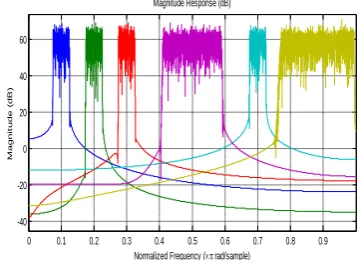
The design example in this section consists of four Blue Tooth (BT) channels placed between 1.5 and 2.5 MHz, 3.5 and 4.5 MHz, 5.5 and 6.5 MHz, 13.5 and 14.5 MHz, respectively, one Zigbee channel placed between 8-12 MHz, and one channel of Wideband Code Division Multiple Access (WCDMA) placed between 15-20 MHz as shown in Figure 1, will be used for the multiband channelization scenario. The sampling frequency is considered as 40 MHz.
Fig 1: Nonuniform Channelization of of BT, Zigbee and WCDMA Design Example
Four types of FBs will be used to extract the multibands in Figure 1 based on the coefficient decimation method. All channels in Figure 1 can be obtained using the CDM after normalizing the frequency specifications of every standard. The normalized bandwidth (BW) of BT, Zigbee and WCDMA channels are 0.05, 0.2 and 0.25 respectively. The normalized transition bandwidth (TBW);for BT, Zigbee and WCDMA channels are 0.0025, 0.01 and 0.025. Ripple;specifications for Zigbee ;as well as WCDMA are 0.1,;−40 dB and for BT are 0.1, −55 ;dB. The passband of the modal filter is chosen 0.025 (𝑓𝑝 = 0.025, 𝑓𝑠 = 0.0275). The peak pass ripple (PPR) is 0.1dB and the stopband attenuation (SA) is -55 dB. The modal filter frequency response is shown in Figure 2.
Fig 2: Modal Filter Frequency Response of CDM Multi-Band
By applying CDM-I with 𝑀 = 20 to the modal filter, a frequency response as in Figure 3 (a) is obtained. Four BT channels can be extracted from Figure 3 (a) using four sharp TBW bandpass masking filters of order (119), designed using (4). By applying CDM-II with 𝑀 = 4 to the modal filter, the passband width will be increased by a factor of 4 as shown in Figure 3 (b), and the new passband width will be (0.025 ×4 = 0.1), which represents half the Zigbee baseband bandwidth.
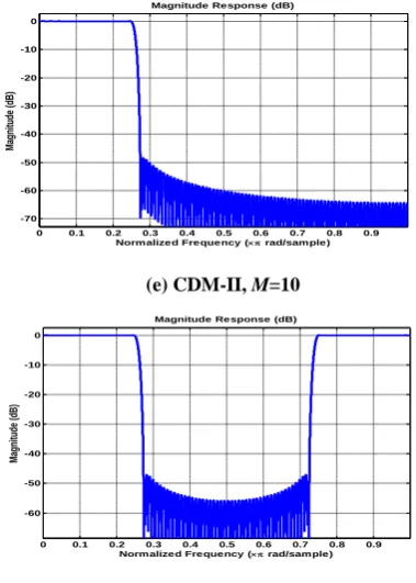
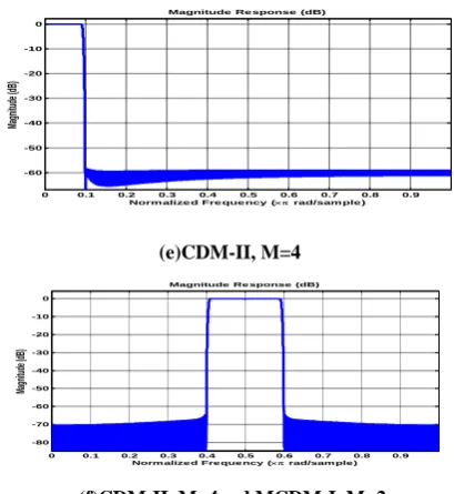
By applying CDM-I with 𝑀 = 2, 4 to the modal filter of new passband width (0.1), frequency responses in Figure 3 (c), (d) are obtained, respectively. The Zigbee channel can be extracted after subtracting the frequency response of Figure 3 (c) from Figure 3 (d). Now by applying CDM-II using M=10 to modal filter, an increase by a factor of 10 occurs to the;
modal filter's passband width ;as observed in Figure 3 (e), and a passband width of (0.025 ×10 = 0.25) is obtained, which is the bandwidth of WCDMA. By applying CDM-I
(a) CDM-I, M=2
(b) CDM-II, M=4
(c) CDM-II, M=4 and CDM-I, M=2
(d) CDM-II, and CDM-I, M=4 0 0.1 0.2 0.3 0.4 0.5 0.6 0.7 0.8 0.9
-40 -20 0 20 40 60
Normalized Frequency ( rad/sample)
M
a
g
n
it
u
d
e
(
d
B
)
Magnitude Response (dB)
0 0.1 0.2 0.3 0.4 0.5 0.6 0.7 0.8 0.9
-70 -60 -50 -40 -30 -20 -10 0
Normalized Frequency ( rad/sample)
Magnitude (dB
)
Magnitude Response (dB)
0 0.1 0.2 0.3 0.4 0.5 0.6 0.7 0.8 0.9 -70
-60 -50 -40 -30 -20 -10 0
Normalized Frequency ( rad/sample)
Magnitude (dB
)
Magnitude Response (dB)
0 0.1 0.2 0.3 0.4 0.5 0.6 0.7 0.8 0.9
-50 -40 -30 -20 -10 0
Normalized Frequency ( rad/sample)
Magnitude (dB
)
Magnitude Response (dB)
0 0.1 0.2 0.3 0.4 0.5 0.6 0.7 0.8 0.9
-70 -60 -50 -40 -30 -20 -10 0
Normalized Frequency ( rad/sample)
Magnitude (dB
)
Magnitude Response (dB)
0 0.1 0.2 0.3 0.4 0.5 0.6 0.7 0.8 0.9
-70 -60 -50 -40 -30 -20 -10
Normalized Frequency ( rad/sample)
Magnitude (dB
)
26 (e) CDM-II, M=10
(f) CDM-II, M=10 and CDM-I, M=2
Fig 3: Using CDM on Modal Filter of Figure 2 to obtain the multi-channels
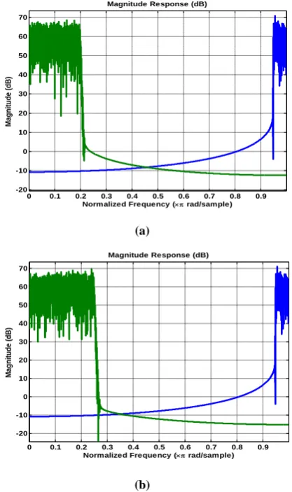
with M = 2 to the modal filter of new passband width (0.25), frequency response in Figure 3 (f) is obtained. The WCDMA channel can be extracted after performing spectral subtraction to the frequency response of Figure 3 (e) and the frequency response of Figure 3 (f). Different multi-band frequency responses in Figure 1 can be obtained by the MCDM-I and II, using different values of M. A modal filter in Figure 2, that has the desired frequency edges and ripple specifications of nonuniform CDFB, is designed. Figure 4 (a) shows the frequency response of the modal filter after performing MCDM-I, using M=10. The subbands BT1, BT3 and BT4 can be extracted using low order (39) wide-TBW masking filters as shown in Figure 4 (a). Figure 4 (b) shows the frequency response of the modal filter after performing MCDM-I, using
M=5 in which, BT2 can be extracted using a low order (19) wide-TBW masking filter. Zigbee channel can be achieved by applying MCDM-II, with M=4 on the modal filter (Figure 4 (c)), then performing MCDM-I, with M=2 on the resulting frequency response. Now perform MCDM-II, with M=10 to get the WCDMA channel as shown in Figure 4 (d).
(a) MCDM-I, M=10
(b) MCDM-I, using M=5
(c) MCDM-II, M=4
(d) MCDM-II, 𝑴 = 𝟏𝟎
Fig 4: Using MCDM Operation to Obtain the Multi-Bands
A FB based ICDM-II can be used to extract channels of multi- standard in Figure 1.In order to design the modal filter according to design steps in [9], the modal filter's passband width is fixed at 0.025 and "the decimation factors required to obtain the three standards" in Figure 1 using ICDM-II operations, are {3, 5, 7, 9, 10, 11, 13, 16, 24}. BT1 can be extracted after subtracting the frequency response resulting from performing CDM-II, with M=3 from the frequency response resulting from performing CDM-II, with M=5. Similarly the other BT channels can be extracted after performing frequency response subtracting using M=7, 9, 11, 13. The Zigbee channel can be extracted after subtracting the frequency response obtained after performing CDM-II, with
M=16 from that resulting from applying CDM-II, with M=24. WCDMA channel can be obtained after performing MCDM-II, with M=10. According to design steps in section 3.5, the frequency edges of the modal filter are (𝑓𝑝 = 0.025, 𝑓𝑠 = 0.025142) and the ripples specifications are (δ p = 0.1dB, δs = -55dB). The maximum required decimation factor is 24 and corresponding Least Common Multiple (LCM) is 720720. The implementation of such filter is not possible and
0 0.1 0.2 0.3 0.4 0.5 0.6 0.7 0.8 0.9
-70 -60 -50 -40 -30 -20 -10 0
Normalized Frequency ( rad/sample)
Magnitude (dB
)
Magnitude Response (dB)
0 0.1 0.2 0.3 0.4 0.5 0.6 0.7 0.8 0.9
-60 -50 -40 -30 -20 -10 0
Normalized Frequency ( rad/sample)
Magnitude (dB
)
Magnitude Response (dB)
0 0.1 0.2 0.3 0.4 0.5 0.6 0.7 0.8 0.9
-70 -60 -50 -40 -30 -20 -10 0
Normalized Frequency ( rad/sample)
Magnitude (dB
)
Magnitude Response (dB)
0 0.1 0.2 0.3 0.4 0.5 0.6 0.7 0.8 0.9
-70 -60 -50 -40 -30 -20 -10 0
Normalized Frequency ( rad/sample)
Magnitude (dB
)
Magnitude Response (dB)
0 0.1 0.2 0.3 0.4 0.5 0.6 0.7 0.8 0.9
-60 -50 -40 -30 -20 -10 0
Normalized Frequency ( rad/sample)
Magnitude (dB
)
Magnitude Response (dB)
0 0.1 0.2 0.3 0.4 0.5 0.6 0.7 0.8 0.9
-70 -60 -50 -40 -30 -20 -10 0
Normalized Frequency ( rad/sample)
Magnitude (dB
)
Magnitude Response (dB)
0 10 20 30 40 50 60 70
Magnitude (dB
)
Magnitude Response (dB)
0 10 20 30 40 50 60 70
Magnitude (dB
)
27 inefficient. Hence, the center frequency locations of various
standards have to be changed. Suppose the scenario of Figure 5. The Zigbee and BT channels are simultaneously exist on the wideband input signal spectrum in Figure 5 (a). Whereas, the CDMA and BT channels are simultaneously exist on the wideband input signal spectrum in Figure 5 (b). The BT, Zigbee and WCDMA channels can be obtained after performing CDM-II with M=1 to M=6, as shown in Figure 6.
(a)
(b)
Fig 5: (a) Input signal spectrum with Zigbee and Bluetooth Channels (b) Input signal spectrum Occupying
BT and WCDMA Channels
The passband width is selected as 0.05 for the modal filter. The minimum TBW amongst three standards is 0.0025 and the maximum decimation factor required is 6. Hence the TBW of the modal filter is 0.00042. Let 𝑓𝑝= 0.05 and 𝑓𝑠= 0.05042, taking into account the worst case SA of three standards which is -55 and the PPR of 0.1. In order to obtain frequency bands associated with the three standards, ICDM-II operations are used with corresponding decimation factors {1, 2, 3, 4, 5, 6}. The LCM of these values of M is 120. The modal filter's order is 14520 [9]. If the frequency responses in Figure 6 (a) and (b) are spectrally subtracted from each other, two BT channels, happening at various time occasions can be obtained. Similarly, spectral subtraction can be performed in Figure 6 (c), (d), (e) and (f) to obtain uniform BT frequency bands. Zigbee channels can be obtained after performing spectral subtraction to Figure 6 (e) and (a) or Figure 6 (f) and (b). WCDMA can be obtained after performing spectral subtraction to Figure 6 (f) and (a) or is obtained directly from
Figure 6 (e). The scenario of Figure 5 (a) can be realized by using the CDM-II output response for M=4 to obtain Zigbee channel and using MCDM-II with M=1 to extract the BT channel. Whereas, the scenario of Figure 5 (b) can be obtained
(a)ICDM-II, M=1
(b) ICDM-II, M=2
(c)ICDM-II, M=3
(d) ICDM-II, M=4
0 0.1 0.2 0.3 0.4 0.5 0.6 0.7 0.8 0.9
-20 -10 0 10 20 30 40 50 60 70
Normalized Frequency ( rad/sample)
Magnitude (dB
)
Magnitude Response (dB)
0 0.1 0.2 0.3 0.4 0.5 0.6 0.7 0.8 0.9
-20 -10 0 10 20 30 40 50 60 70
Normalized Frequency ( rad/sample)
Magnitude (dB
)
Magnitude Response (dB)
0 0.1 0.2 0.3 0.4 0.5 0.6 0.7 0.8 0.9
-70 -60 -50 -40 -30 -20 -10 0
Normalized Frequency ( rad/sample)
Magnitude (dB
)
Magnitude Response (dB)
0 0.1 0.2 0.3 0.4 0.5 0.6 0.7 0.8 0.9
-60 -50 -40 -30 -20 -10 0
Norm alized Fre que ncy ( rad/sample )
Magnitude (dB
)
Magnitude Re sponse (dB)
0 0.1 0.2 0.3 0.4 0.5 0.6 0.7 0.8 0.9
-60 -50 -40 -30 -20 -10 0
Normalized Frequency ( rad/sample)
Magnitude (dB
)
Magnitude Response (dB)
0 0.1 0.2 0.3 0.4 0.5 0.6 0.7 0.8 0.9
-60 -50 -40 -30 -20 -10 0
Normalized Frequency ( rad/sample)
Magnitude (dB
)
(e) ICDM-II, M=5
(f) ICDM-II, M=6
Fig 6: ICDM-II Operations for M=1 to M=6
by using the CDM-II output response with M=5 to extract the WCDMA channel and using MCDM-II, with M=1 to extract Bluetooth channel.
ICDM-FB is able to perform the nonuniformchannelizationin the design example of Figure 1. The design steps in [13] are used to design the ICDM-FB to extract different channels in Figure 1. The passband width of modal filter which is the greatest common divisor (GCD) of (0.025, 0.1, 0.125), is selected as 0.025. The values of a decimation factor required for obtaining the lowpass and highpass bandwidths corresponding to the BWs of the various standards are D1 = 1,
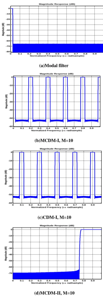
D2 = 4, and D3 = 10. The modal filter TBW is computed as 0.0025. Hence, the edge frequencies of the modal filter are (𝑓𝑝 = 0.0225 and 𝑓𝑠 = 0.025). The three values of decimation factor groups that are used in the operations of ICDM-I are identified as 10, 2, and 1 corresponding to BT, Zigbee and WCDMA respectively. The SA of the modal filter is computed to be -65 dB and the passband peak ripple is 0.1 dB. A modal filter is designed to have an order of 2928 according to the computed specifications as shown in Figure 7 (a). By performing suitable ICDM operations on the modal filter the corresponding frequency responses can be obtained as can be described below.
Perform CDM-I on the modal filter by M=10 to get the frequency response including BT2 band as shown in Figure 7 (b). To extract the BT2 channel, a low order masking filter (39) is designed. BT1, BT3, and BT4 channels can be achieved after applying MCDM-I with M = 10 as shown in Figure 7 (c). These three channels can be extracted by using
three masking filters of low order (39) MF1, MF3 and MF4. Perform MCDM-II; with M=10 as in Figure 7 (d), to extract WCDMA channel. Now to obtain the Zigbee channel, firstly perform CDM-II by M=4, as shown in Figure 7 (e), then perform MCDM-I by M = 2 to the frequency response in Figure 7 (e) to obtain the Zigbee channel as shown in Figure 7 (f). Hence, the six channels of different standards are extracted by using the ICDM- FB.
(a)Modal filter
(b)MCDM-I, M=10
(c)CDM-I, M=10
(d)MCDM-II, M=10
0 0.1 0.2 0.3 0.4 0.5 0.6 0.7 0.8 0.9
-70 -60 -50 -40 -30 -20 -10 0
Normalized Frequency ( rad/sample)
Magnitude (dB
)
Magnitude Response (dB)
0 0.1 0.2 0.3 0.4 0.5 0.6 0.7 0.8 0.9
-60 -50 -40 -30 -20 -10 0
Normalized Frequency ( rad/sample)
Magnitude (dB
)
Magnitude Response (dB)
0 0.1 0.2 0.3 0.4 0.5 0.6 0.7 0.8 0.9
-80 -70 -60 -50 -40 -30 -20 -10 0
Normalized Frequency ( rad/sample)
Magnitude (dB
)
Magnitude Response (dB)
0 0.1 0.2 0.3 0.4 0.5 0.6 0.7 0.8 0.9
-60 -50 -40 -30 -20 -10 0
Normalized Frequency ( rad/sample)
Magnitude (dB
)
Magnitude Response (dB)
0 0.1 0.2 0.3 0.4 0.5 0.6 0.7 0.8 0.9
-60 -50 -40 -30 -20 -10 0
Normalized Frequency ( rad/sample)
Magnitude (dB
)
Magnitude Response (dB)
0 0.1 0.2 0.3 0.4 0.5 0.6 0.7 0.8 0.9
-70 -60 -50 -40 -30 -20 -10 0
Normalized Frequency ( rad/sample)
Magnitude (dB
)
29 (e)CDM-II, M=4
(f)CDM-II, M=4and MCDM-I, M=2
Fig 7: ICDM Operations for Obtaining Multi-Channels
3.1
Complexity Comparison
The complexity of the filter bank can be represented by involved multiplications number. Thus, the multiplications number required in CDFB implementation represent the sum of multiplications number required for modal filter's implementation and the multiplications number required for implementation of masking filters. Using (4), the modal filter's length in the nonuniform CDFB is 2394 and the over designed modal filter order using 𝑀𝑚𝑎𝑥 = 20 is 3088 according to (6). The order of the masking filters that used for masking BT channels and CDMA channel are 119, 18 respectively. However, the modal filter has been used with M
= 20 for BT channels extraction, while M = 4 followed with M
= 4 is used in extraction of Zigbee channel, and M = 10 followed by M = 4 for extraction of WCDMA channel. Therefore, the total number of multiplications involved is ⌈3089/2⌉ + (⌈120/2⌉ ∗ 4) + ⌈19/2⌉ = 1795.
The length of the modal filter in the nonuniform MCDM-FB;
is 2394 and the over designed modal filter order using 𝑀𝑚𝑎𝑥 = 10 is 2927 according to (6). The order of the masking filters that used for masking BT1, BT3 and BT4 channels is 39, whereas the masking filter used for masking BT2 is of order 18. Hence, the total number of multiplications involved is ⌈2927/2⌉ + (⌈40/2⌉ ∗ 3) + ⌈19/2⌉ = 1534. It can be noted that, the MCDM has no masking filter computation overhead (to extract Zigbee and CDMA channels) or frequency response subtraction compared with CDM. The unified design example is difficult to be implemented using the ICDM-II operations as it requires a huge filter length. According to specified modal filter's specifications, its order is 14404. The values of decimation factors required to obtain the three standards channels in ICDM-II operations are (M=1 to M=6). The LCM of the employed decimation factors is 120, which leads to a filter order of 14520. Due to symmetry property realized by implementation of transposed direct form, the total multiplications number needed is ⌈14521/ 2⌉7261. Whereas in CDM-II based FB, the required values of the decimation factor are "(M=1 to M=20) and the maximum decimation factor is 20 and the
corresponding filter order is a huge number which is impossible to implement. Hence the maximum decimation factor required in the ICDM-II based FB design is half of that involved in the CDM-II based FB.
For the nonuniform ICDM-FB, the filter length of the modal filter is found to be 2928 taking in consideration the deterioration in SA problem in various values of M. The order of the masking filters that used for masking BT1, BT2, BT3 and BT4 channels is 39. Hence, the total number of multiplications involved is ⌈2929/2⌉ + (⌈40/2⌉ ∗ 4) = 1545. The complexity of the CDM based FBs designed to serve nonuniform channelization, is summarized in Table 1. It can be noted from Table 1 that the complexity of MCDM-FB is less than other types of CDM based FBs. Whereas, the ICDM-II based FB has the highest complexity.
3.2
Flexibility Comparison
The flexibility of a filter bank can be defined by the number and locations of distinct channels obtained from that FB. It can be observed that the resolution of π/M is achieved for the "center frequency in the resultant multiband in MCDM and ICDM operations". While possible center frequency subband locations of 2π/M are achievable in the CDM. In ICDM-II based FB, any center frequency can be achieved since the CDM-II is used with spectrul subtraction.
Table 1: Comparison of Multiplication Complexity: Design example of Nonuiform Channelization
CDFB MCDM ICDM
ICDM-II
Modal filter
length (𝑙𝑀𝑜𝑑) 3089 2927 2929 14521
Masking filter
length (𝑙𝑀𝑎𝑠) (40) + (120*3)= 400
(40*2)+ 19=99
40*4= 160
_
No. of multiplications =(⌈𝑙𝑀𝑜𝑑/ 2+𝑙𝑀𝑎𝑠/2)
{⌈3089/ 2+40/2
+(3* ⌈120/2⌉)}
=1745
{⌈2927/2 ⌉ +
(⌈40/2 ⌉ ∗ 3) + ⌈19/2⌉}
= 1534 { ⌈2929/
2
+(4* ⌈40/
2)}
=1545 ⌈14521
/2⌉
= 7261
Total no. of multiplications
1745 1534 1545 7261
4.
CONCLUSION
Conventional spectrum sensing methods use filter bank that employs DFTFB while, in this paper several methods based on the coefficient decimation method are designed to serve a nonuniform channelization for wideband spectrum sensing in
0 0.1 0.2 0.3 0.4 0.5 0.6 0.7 0.8 0.9
-60 -50 -40 -30 -20 -10 0
Norm alize d Fre que ncy ( rad/sam ple )
Magnitude (dB
)
Magnitude Re sponse (dB)
0 0.1 0.2 0.3 0.4 0.5 0.6 0.7 0.8 0.9
-80 -70 -60 -50 -40 -30 -20 -10 0
Norm alize d Fre que ncy ( rad/sam ple )
Magnitude (dB
)
cognitive radios. Four types of CDM based FB are explained in this paper with the aid of a design example. Complexity analysis regarding the design example clearly specify that the MCDM approach offers a better filter length saving compared to that of the other methods due to reduced decimation factors involved. The flexibility by means of the number of resulting subbands and their locations is better in ICDM-II based FB and the worst in the CDM based FB. A combination of coefficient decimation method and coefficient interpolation method can be performed to employ a rconfigurable filter bank with reduced complexity for future work.
5.
REFERENCES
[1] P. P. Vaidyanathan, “Multirate digital filters, filter banks, polyphase networks, and applications: a tutorial”. Proceedings of the IEEE, Volume 78, No. 1, pp. 56-93, August 2002.
[2] A. Ambede, K. G. Smitha, et al., "A New Low Complexity Uniform Filter Bank Based on the Improved Coefficient Decimation Method", Circuits, Systems, and Signal Processing, Volume 32, No. 6, pp. 2543-2557, December 2013.
[3] J. Mitola and G. Q. Maguire, “Cognitive radio: Making software radios more personal”, IEEE Personal Communications, Volume 6, No.4 pp. 13-18, August 2002.
[4] S. Haykin, “Cognitive radio: Brain-empowered wireless communications”, IEEE J. Sel. Areas Commun., Volume 23, pp. 201-220, 2005.
[5] R. Mahesh and A. P. Vinod, “Coefficient decimation approach for realizing reconfigurable finite impulse response filters”, Circuits and Systems
[6] M. Lin, A. P. Vinod, et al., " Very Low Complexity Variable Resolution Filter Banks for Spectrum Sensing in Cognitive Radios Using Multi-Stage Coefficient Decimation", Wireless Communications, Networking and Mobile Computing, 5th International Conference on, pp. 1-4, 2009.
[7] R. Mahesh and A. P. Vinod" Reconfigurable Discrete Fourier Transform Filter Banks for Multi-Standard Channelizers" Signal Processing and Communications (SPCOM), pp. 1 – 5, July 2010.
[8] A. Ambede, K. G. Smitha, et al., “A modified coefficient decimation method to realize low complexity FIR filters with enhanced frequency response flexibility and passband resolution”, Telecommunications and Signal Processing (TSP), pp. 658 – 661, July 2012.
[9] A. Ambede, K. G. Smitha, et al., “An Improved Coefficient Decimation based Reconfigurable Low Complexity FIR Channel Filter for Cognitive radios” Communications and Information Technologies (ISCIT), pp. 22 – 27, October 2012.
[10]R. Mahesh and A. P. Vinod, “A low-complexity flexible spectrum-sensing scheme for mobile cognitive radio terminals,” IEEE Transactions on Circuits and Systems II, Volume 58, No.6, pp. 371-375, June 2011.
[11]Y. Lim, “Frequency-response masking approach for the synthesis of sharp linear phase digital filters”, IEEE Transactions on Circuits and Systems, Volume 33, No.4 pp. 357- 364, January 2003.
[12]R. Mahesh and A. P. Vinod, “Low complexity flexible filter banks for uniform and non-uniform channelisation in software radios using coefficient decimation” IET Circuits, Devices & Systems, Volume 5, No. 3, pp. 232– 242, May 2011.
[13]A. Ambede, A. P. Vinod, et al., " Flexible Low Complexity Uniform and Nonuniform Digital Filter Banks With High Frequency Resolution for Multistandard Radios", IEEE Transactions on Very Large Scale Integration (VLSI) Systems, Volume 23, No. 4, pp. 631 – 641, March 2015.