Design of a Temperature Sensitive Voltage
Regulator for AC Load using RTD
Tasnuva Chowdhury*1
Lecturer, Department of EEE,
American International University- Bangladesh (AIUB), Dhaka, Bangladesh [email protected]
Haider Bulbul2
B.Sc. in EEE
American International University- Bangladesh, Dhaka, Bangladesh
Abstract: Voltage regulation of an electrical load has always been a necessity with the variation of atmospheric
temperature. Human body undergoes troubles and sufferings when there is a certain change arises in the surrounding temperature and he or she might not be able to cope up with the sudden environmental change. To make life easier and better adjusted to the natural temperature change, a temperature sensitive voltage regulator have been designed and implemented in this work. Here a temperature sensor called Resistor Temperature Detector (RTD) is used for temperature sensing purpose which delivers its output to the input of a voltage controller circuit and can subsequently control the speed of any light AC electrical load according to the variable temperature. In our project , the RTD was able to take the reading from 26oC to 38oC accurately. Moreover, the room temperature is also made visible by two 7-segment display. The circuit is synchronized and tested with the cheapest AC load (bulb) available in the market.
Keywords: LM35 RTD, DIAC-TRIAC Phase control circuit, 4N25 Opto-coupler, Speed control
1. Introduction:
Temperature measurement, a vital part of most industrial operations, is typically accomplished by a temperature sensor. For temperature sensing purpose various temperature sensors have got their commercial recognition. Among them Thermocouples and RTD’s are widely used. In this paper, I have utilized RTD of LM35 series for the temperature measurement purpose, and a slight change in the temperature has created significant effect in controlling the speed of an AC load (here the intensity of an incandescent bulb).Along with the variable temperature, different resistance, hence variable voltage drop was generated which was further utilized for intensity or may be speed adjustment purpose. Several methods are available for voltage controlling; where the source can be either a dc or an ac and the load as well can either be a dc or an ac.Various control modes are available for voltage control such as: Phase -control, Switching - control, Chopper- control. [9] In my project, I have emphasized on phase control method for voltage control purpose. I used a DIAC – TRIAC phase controlled circuit to achieve the desired speed or intensity of the load along with the changing temperature, where the temperature sensor and phase control circuit which was physically isolated for safety purpose, was finally coupled via an opto coupler of 4N25 series. The similar type of jobs is done using thermocouples, but I relied on RTD for its diverse qualities.
1.1 Reasons behind choosing RTD:
Choosing the right sensor for a particular application requires an understanding of the basics of RTDs and thermocouples. A thermocouple is made up of two dissimilar metals, joined together at one end that produces a voltage (expressed in millivolts) with a change in temperature. Any two dissimilar metals may be used to make a thermocouple. The most common Thermocouples are types E, J, K, R, S, and T [3, 5] .While reading the temperature measurement errors can be introduced with thermocouples. Since the voltage created by the thermocouple is due to the bonding of two dissimilar metals, the introduction of other junctions to the circuit results in voltage changes that are referred to as cold junction errors. If the temperature at the connections is determined, these errors can be corrected by a process called cold junction compensation. This is carried out at the receiving device, which is usually the signal conditioner. [10]
RTD is another type of sensor whose resistance changes fairly linearly as temperature changes. A controller measures the resistance value and converts it into a temperature reading. Unlike a thermocouple there is no electrical signal generated by a RTD. So, a controller must measure the resistance by passing a small current through RTD. Based on current and voltage it measures the resistance according the Ohms law. A RTDs’ resistance value increases as the temperature increases and decreases with the decrease in temperature. That’s why its Temperature versus Resistance curve always comes linear and is also known as a “TCR” or temperature co-efficient of resistance curve. Similar is the case with variation in voltage (in mV) that occurs approximately linearly with the variation in temperature. [3, 5]
RTD is the sensor of choice when sensitivity and application flexibility are the most important criteria whereas when it comes to the component cost, a thermocouple is cheaper than RTD. The use of platinum RTD may be preferred when a temperature measurement accuracy of better than 1°F or 1°C is required. RTD provides reliable output over a period. It is found that the calibration of the RTD outcome is much easier than other measurements. Another important characteristic of the 3 wire RTD LM35 is that it draws only 60 micro amps from its supply and possesses a low self-heating capability. [11] The sensor self-heating causes less than 0.1oC temperature rise in still air. Moreover, they are suitable for low power application devices.
Thermocouple offers a wide range of accuracy, particularly at elevated temperatures, making it difficult for a reliable output. In this way several factors must be considered when selecting the type of sensor to be used in a specific application: temperature range, accuracy, response time, stability, linearity and sensitivity. A brief summary is presented in table1.
Table1. Temperature sensor selection criterion [5, 8]
Features RTD Thermocouple
Temperature Range –200°C to 850°C –190°C to 1821°C –328°F to 1562°F –310°F to 3308°F Accuracy ±0.001°F to 0.1°F ±1°F to 10°F
Response Time Moderate Fast
Stability Stable over long Not as stable as RTD <0.1% error/5 yr. 1°F error/yr.
Accuracy ±0.001°F to 0.1°F ±1°F to 10°F High sensitivity Low sensitivity
2. Designing of the Circuit:
The main target of this voltage regulator circuit is to control the speed of an AC Load in proportion with the temperature. The whole circuit consists of three major parts: first part is for input power control, second one is for temperature sensing and display purpose and the last part is for the AC load controlling as well as motor controlling unit.
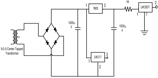
2.1 The input circuit:
The major electrical and electronic components of the input power control unit are: Transformer, Bridge rectifier, voltage regulator IC 7805 and a variable voltage regulator LM 317. At first a 220V AC supply voltage is stepped down by a 9-0-9V center-tapped transformer (figure 2), which is further converted into dc voltage by using a full wave bridge rectifier (figure 3). This 9V dc voltage goes to both of the voltage regulator IC 7805 and variable voltage regulator LM 317 (figure 8). When IC 7805 gets its input 9V, it produces a constant 5V dc output which is used to run the ICs’ used in the circuit (figure 8).
Fig. 1: Center Tapped Rectifier for Generating Input
The output of LM 317 directly goes to A/D converter ADC 0804, where half of the reference voltage which is 2.5 V is needed. A LM 317 can produce an output voltage which ranges from 1.2V to 37V. By varying the variable resistor, connected to the LM 317’s adjustable port, the desired reference voltage that is 5V can be supplied for ADC0804.
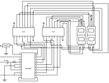
2.2 Temperature sensing and display unit:
6 7 9 19 20 18 17 16 8 10 4 1 15 14 13 12 ADC0804 2 11 3 5 8 9 1 16 7447 8 9 1 16 7447 1K 150 uF 1K 1K LM35DT 3 2 1
Fig.2: Temperature sensing and display unit
ADC’s pin no. 9 gets its input from LM317’s output, where it is adjusted as the half of reference voltage that is equivalent to 2.5V. The ADC 0804 has 8-bit output. This 8-bit output is divided into two parts: first 4 bits are MSB and the rest 4 bits are LSB. This 4-bit LSB and MSB go to a two 7-segment display driver IC 7447. When IC 7447 gets its input from ADC 0804, it produces corresponding output. As a result, it is possible to see the current room temperature in the two 7-segment displays.
2.2.1 Graphical Explanation of Data’s available from RTD:
Here in this project I have used a RTD of LM35 series (LM 35DT) to get accurate conversion of temperature in respective voltage drops (table 1). This type of sensor is the most widely used for practice; besides its cheap price it has quite good linearity. The LM35 Series are precision integrated-circuit temperature sensors, whose output voltage is linearly proportional to the Celsius (Centigrade) temperature. It has the capability to visualize the resistance drop from -55°C to 150°C temperature range. But in our experiment we got the suitable data’s’ for the temperature ranges 26°C to 38°C.The room temperature was varied using an air conditioner remote. The data’s found through this experimental procedure (shown in table 2) shows that for each degree temperature variation the RTD is providing a 100 mV drop nearly, which satisfies the RTDs’ property and thereby maintains the linear relationship between Temperature change and voltage drop.
Table 2:Equivalent voltage output according to different temperature drops.
Temperature shown on 7-segment display (ºC)
26 28 30 32 34 36 38
Equivalent voltage output of LM 35DT (mV)
Fig. 3: Temperature Vs. Voltage Graph.
2.3 Controlling the speed of load in accordance with the temperature variation via opto coupling:
The last portion of the circuit is the motor controlling unit, which is adjusted according to the atmospheric temperature. Here at first the temperature sensor LM 35DT’s output is amplified by an op-amp LM 324. This amplified output will go through an opto-coupler IC 4N25. An opto-coupler is used to couple two different voltage rating and two different voltage characteristics circuits. The opto-coupler output pins are connected to the load through a DIAC-TRIAC phase control circuit. This DIAC-TRIAC phase control circuit controls the speed of AC Load according to the temperature change. [1]
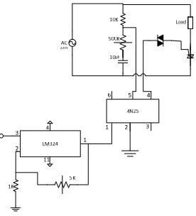
2.3.1 Configuration of a DIAC- TRIAC Phase control circuit:
Fig. 4: Controlling of Speed with DIAC –TRIAC Phase Control Circuit
current flows. Since the DIAC and TRIAC perform as the open circuit in this stage, the result is an RC network as illustrated in the fig 6. Due the nature of this type of series RC network the voltage across the capacitor leads the line voltage by a phase angle that is determined by the resistance and capacitance of the RC network. The magnitude of the capacitor voltage Vc is also dependent on this values. Here in the phase control circuit on either alternation, the
capacitor begins charging through the variable resistor. The Voltage drop across the DIAC is analogous to the voltage drop across the capacitor. As soon as the capacitor voltage reaches the break over potential, the DIAC fires (the break over voltage for a DIAC is 30V) and make the TRIAC on (figure 4).
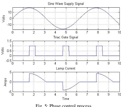
Fig. 5: Phase control process
AC 6 7 9 19 20 18 17 16 8 10 4 1 15 14 13 12 ADC0804 2 11 3 5 8 9 1 16 7447 8 9 1 16 7447 4N25 LM324
6 5 4
2 1 3 4 11 3 2 1 10K 500 K Loa d 5K 10u F 220V 1K 1K 150 uF 7805 LM317 1000u F 1 2 3 3 1
9-0-9 Center Tapped Transformer LM35DT 2 1 1K 1000u F 1K 1K 3
Fig.6: Overall circuit diagram
Fig.7: Overall circuit picture
3 Conclusions:
project will also be successful in power saving if people take interest in implementation of this device in their homes and offices. It is very important for developing countries to provide fully automatic voltage regulation of home appliances and hence it can save energy and minimize monthly electricity cost. Moreover, developments related to the main theme of the project can create new areas of research and development in near future.
Acknowledgements:
I would like to thank my students Tanbir Rahman, Shakhawat Hossain Miah , Department of EEE AIUB, for helping me completing the design project.
It was a wonderful experience to work while completing the research and preparing this Thesis report. I would like to express my heartfelt gratitude to everyone who might not have been directly related to this project but still had an immense impact on my work-especially
References:
[1] Charles A. Schuler and William L. Mcnamee. (1986).Industrial Electronics and Robotics,McGraw- Hill. [2] Chitode J. S. (2009).Power Electronics –III, 1st edn.Technical Publications,Pune, India, , 1(10), pp. (36-46).
[3] Fraden Jacob. (2004).Handbook of Modern Sensors : Physics, Designs & Applications 3rd edn. Springer _ Verlag, NewYork, INC, pp.( 457-451) & pp.(484-486).
[4] Godse A.P. and Godse D. A.(2010). Electronics and Microprocessors,1st edn.Technical Publications,Pune, India, 4(3-4), pp. (18-28).
[5] McMillan Gregory K. (1999). Process/ Industrial Instruments and control Handbook,5th edn. McGraw- Hill ,4(12-27).
[6] Rashid Mohammad H. (1994): Power Electronics-circuits device and Application, Prentice Hall of India Pvt Ltd, India. [7] Sen P.C. (1987). Power Electronics, Tata McGraw Hill Publishing Company Ltd, India, 1(1-12), pp.(1-133). [8] www.sensorsmag.com
[9]David W. Borst, Edward J. Diebold and Frank W. Parrish, Voltage Control by Means of Power Thyristors, NJ:IEEE press, 1966 [10] A. Paul Brokaw, A Monolithic Conditioner for Thermocouple Signals, NJ: IEEE press, 1983