A New GPS-based Digital Protection System for Smart
Grids in Loop Structure
X. Liu
1,*, M. Steurer
1and M. Yu
21FSU, Center for Advanced Power System, 2000 Levy Ave, Tallahassee, FL 32310 2FSU, Dept. of ECE, 2525 Pottsdamer Street, Tallahassee, FL 32310
Abstract
This paper presents a new digital protection system to solve the protection challenges in future smart grids, i.e., fast protection and fault isolation in a loop-structured system with limited magnitude of fault current. The new system combines two protection algorithms, i.e., a differential protection as the primary algorithm and an overcurrent protection as the backup one. The new system uses real-time Ethernet and digital data acquisition techniques to overcome the restriction on data transmission over large grids. The current measurements at different locations are time-synchronized by GPS clocks, and then transmitted to a central computer via the Ethernet. As opposed to digital relays which often contain PMU functionality nowadays, this approach uses time stamps on the instantaneous current values. We build a prototype of the new system on a test-bed. The results from simulations and experiments have demonstrated that the protection system achieves fast and accurate protection.
Keywords: Smart grid protection, differential protection, GPS synchronization, and microcontrollers. Received on 21 August 2014, accepted on 02 September 2014, published on 12 December 2014
Copyright © 2014 X. Liu et al., licensed to ICST. This is an open access article distributed under the terms of the Creative Commons Attribution licence (http://creativecommons.org/licenses/by/3.0/), which permits unlimited use, distribution and reproduction in any medium so long as the original work is properly cited.
doi: 10.4108/ew.1.3.e5
*
Corresponding author. Email:[email protected], *This work is a part of Future Renewable Electrical Energy Distribution Management (FREEDM) project,
which is supported by the ERC Program of the National Science Foundation
1. Introduction
Recently, both industry and academia have realized that smart grids are expected to become the infrastructure that enables the large-scale integration of renewable energy generation into the existing power grids. One example of the smart grid is the Future Renewable Electrical Energy Distribution Management (FREEDM) System, which is a project founded by NSF [1]. A representative example of FREEDM loop system is a distribution system operating at 12.47 kV. The system is supplied by a substation and several renewable generation resources that are distributed in a local loop [2]. The loads and renewable generations are connected to the loop via solid state transformers (SST). Fault isolation devices (FID) (e.g., electronic circuit breakers) are used for fast fault interruption purpose [3], [4]. Compared to the traditional distribution system, the FREEDM system has the following features: (1) it is formed as a loop structure for better efficiency and reliability; (2) the energy transfer between the loads is controlled by SSTs. Thus the power flow can be bidirectional, i.e., there is no upstream and downstream for a fault current. Therefore, there is no upstream and downstream for a traditional
overcurrent protection scheme to use time-current coordination; (3) the magnitude of the fault current is limited to only approximately twice the normal current by a fault current limiter on the infeed from the main utility bus, and as such much lower than the one in conventional distribution systems [5].
The features offer tough challenges for existing protection systems in distribution grids to achieve fast protection and fault isolation. Note that the existing protection systems are normally based on over-current relays and as such are typically not well suited to solve the protection challenges for the smart grids [6]. Therefore, it is a critical need to develop a new protection system to detect and isolate the fault and generate a trip signal to improve power system stability [7].
exchange and compare with each other via a pilot communication wire. The pilot differential protection can cover a very long distance (as long as a TL). However, its application is fixed to single TLs. In the second method, a single relay is placed at a local power component, such as a transformer, generator, or busbar, to provide protection for the component. The reason is that the range of the differential relay is limited to about 25 meters, which is determined by the effective length of copper pilot wire that connects the relay and the component. Instead of directly calculating the measured value, the percentage differential relay uses a percentage characteristic slope to determine a fault, which improves the accuracy and reliability of the protection. Since the FREEDM system is a distribution grid with a range up to a mile, we cannot directly adopt the differential protection algorithms in our application.
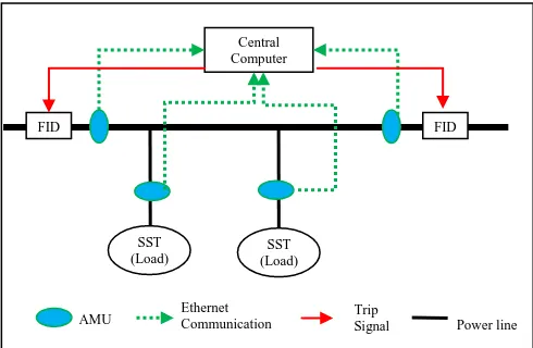
Figure 1. FREEDM loop structure and protection method
As shown in Fig. 1, for fast protection and fault isolation, the FREEDM system in loop structure is divided into several zones. Each zone is terminated by a few FIDs. The loads are supplied to a zone through the SST. In each zone, a protection system performs the fault identification and localization according to a percentage differential protection algorithm. It sends a trip signal to the FIDs in the zone when a fault happens and is detected. The protection goal for a loop-structured system is as follows: for a fault happens anywhere in the loop, if we can isolate the fault within a range, then the rest of the system will remain functional.
2. The proposed protection system
In this section, we point out the disadvantage of the existing differential protection methods. We also propose a new protection system.
These methods cannot be directly applied to the loop-structured zone for the two reasons:
First, the maximum number of input wings in the differential relay is limited to 3, which means that the differential relay is not applicable to a zone with more than one load.
Second, the relay only accepts analog input that can be delivered to a small range. Particularly in a FREEDM loop, AMUs are distributed hundreds of meters away from each other while the analog signal (e.g., the input to the relays) can be delivered to less than tens of meters.
In order to transmit the signal in the range of smart grids, we propose to use data communication protocols, such as Ethernet. Moreover, we need a data acquisition system that converts the local current from analog signals to digital data.
To provide the protection functions for the FREEDM system, we propose a new protection system based on digital data acquisition and Ethernet communication protocols. The new protection system is shown in Fig. 2.
Figure 2. Connection of the protection system within a zone
The central computer executes the protection program in real-time to monitor the zone states and send a trip signal when a fault is identified. The protection program consists of the primary and backup protection algorithms. The primary one is the differential protection algorithm. The method of the differential protection is simple: if the sum of currents in a zone is zero, no fault is indicated; if not zero, a fault in the zone is concluded. The backup one is the overcurrent protection, which only responses to the fault if the primary one fails. Analog merging units (AMU) are distributed in the zone to measure local currents and then send the digitalized current data to the central computer via the Ethernet communication.
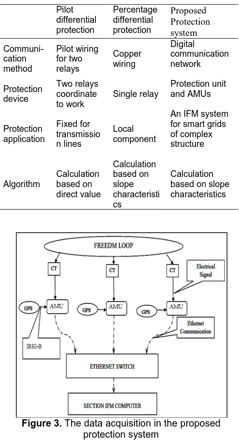
We compare the proposed protection system to the two differential protection methods, as shown in Table 1. It can be seen that the new system combines the advantages of the pilot and percentage differential protection methods.
SST (Load)
Central Computer
AMU Ethernet Communication
tion
Ethernet
communication
FID FID
SST (Load)
Power line Trip
Table 1. Comparison of the three protection methods Pilot differential protection Percentage differential protection Proposed Protection system Communi-cation method Pilot wiring for two relays Copper wiring Digital communication network Protection device Two relays coordinate to work Single relay Protection unit and AMUs Protection application Fixed for transmissio n lines Local component
An IFM system for smart grids of complex structure Algorithm Calculation based on direct value Calculation based on slope characteristi cs Calculation based on slope characteristics
Figure 3. The data acquisition in the proposed protection system
3. The design of the protection system
In this section, we present our design of the protection system, including both hardware and software.
3.1 The hardware design of the protection
system
In this section, we focus on the hardware implementation of the proposed protection system.
The data acquisition system is shown in Fig. 3. Current signals are measured from current transformers (CT) in the
FREEDM loop. AMUs are connected to the output terminals of the CTs. The current signals are converted to digital data by the data acquisition block in the AMU, which is a preprogramed microcontroller. Time synchronization is added to the AMUs using a GPS in the IRIG-B format [11]. The AMUs then send the synchronized data to the central computer through an Ethernet. The major functions of the data acquisition system are converting the analog signals to digital data and synchronizing the digital data over different measurement locations. The bottlenecks of the system are the accuracy of the time synchronization and the number of A/D samples generated in a cycle. The A/D conversion is synchronized by choosing three microcontrollers with the same configuration and performance.
There are two constraints that must be overcome in the communication. One is the bandwidth at an AMU. In this work, we use the microcontrollers with the data rate of 100 Mbps, which are sufficient to send data from the AMU to the central computer. Another is the buffer space available in the Ethernet switch. The communication network operates at a speed of 100 Mbps and the three microcontrollers transmit data at the speed. We also use a gigabit Ethernet switch to ensure sufficient buffer space in the ring buffer of the switch, which reduces the congestion and data loss at the switch [12]. The TCP communication protocol is used to manage data transfer in the Ethernet from each microcontroller to the central computer. The function of the protocol at the AMU is pre-programmed to keep retransmitting any data packet until the packet is delivered to its destination [13].
We note that the retransmission may increase the indeterminacy of the time to deliver the packet. Considering the requirement on the fast and synchronized data acquisition, we chose the microcontroller that has Ethernet output, operates at a device frequency at least 10 times higher than the A/D sampling frequency, and can produce 17 synchronized samples within one cycle at the frequency of 60 Hz.
3.2 The software design for the protection
system
In this section, we present the design of the protection and communication program in the central computer.
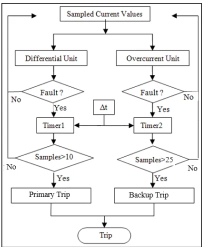
The protection program is the brain of the proposed protection system. Its flow chart is shown in Fig.4. The primary and backup protections work in parallel to protect the smart grid.
The right pipeline is the backup protection. The overcurrent unit exams each sample value according to the overcurrent algorithm. If the value is larger than the overcurrent threshold, then it concludes the existence of a fault and increments the timer. Once a certain number of such consecutive increments are observed, for example, 25, the backup protection generates a trip signal.
The trip signal is generated from both primary and backup units and transmitted to the FIDs through the Ethernet network. Since the trip decision is not made based on 1 or 2 measurements, rather on either 10 or 25 measurements in this work, the decision of the protection program is reliable and accurate. The idea of using 10 samples for the differential protection necessitates a fast data acquisition while enables proper coordination with the FIDs to trip the fault current, which is not possible if using a conventional protection relay.
Figure 4. The flow chart of the protection program
The communication program implements the TCP protocol for data delivery over the Ethernet. The program is composed of a TCP connection block, a TCP read block, and an error and warning block, which are the basic communication components in TCP. The connection block establishes the TCP communication with an IP address and TCP port number in a remote device. When the TCP communication between the computer and micro-controller is established, the read block captures the data from the incoming TCP packets and sends the data with string format to the protection program. With the use of the TCP communication program, the protection program can collect data from the remote AMUs via the Ethernet.
The protection and communication program are implemented on Labview platform, which provides a reliable real-time environment.
4. Validation via Matlab - Simulink
To demonstrate the effectiveness of the proposed protection system, we build a simulation model in Matlab – Simulink to conduct experimental studies.
Figure 5. Simulation of the protection concept
Figure 6. The protection result: 4 scopes represent the output of the protection unit in zone 1, 2, 3, and the
current in the FREEDM loop, respectively. When a fault occurs in zone 2, the protection unit 2 trips while
the units in the other zones remain silent.
The protection test has been repeated with faults in different locations (such as zone 1, 2, and 3) and in different operating conditions. The test results are shown in Fig. 6. It can be seen that the protection system successfully identifies the faults in all cases.
5. Validation via test-bed experiments
In this section, we present the experimental studies on a commercial percentage differential relay and a prototype of the new protection system.
5.1 Performance of the differential protection
algorithm within one zone
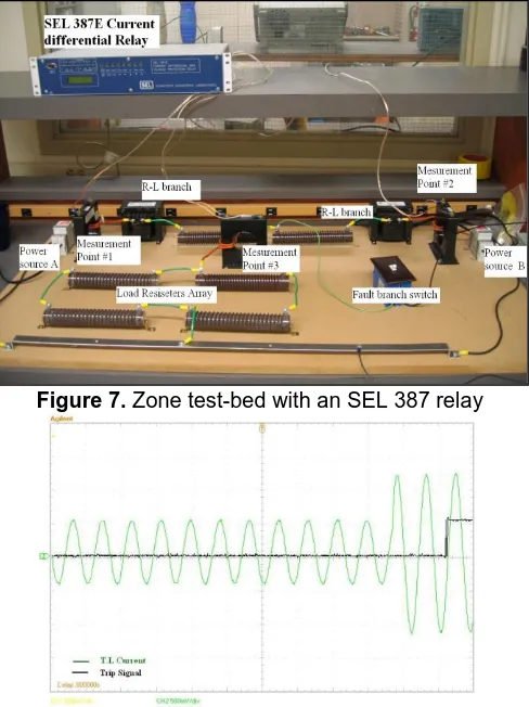
We build a test-bed to model one zone of the FREEDM system for validation purpose, as shown in Fig. 7. There are two standard utility sources that feed the load and two symmetric R-L circuits that represent distribution lines. The fault branch consists of a large resistor that is connected in parallel to the load through a switch. There are three CTs that are distributed at each source terminal and the load for current measuring at corresponding points. The specifications of the test-bed are listed in Table 2.
An SEL 387E current differential relay is set for fault sensing of the test-bed [10]. Both inside and outside faults are tested. The test results are shown in Table 3. It can be seen that the relay successfully identifies the fault inside or outside the zone. The relay generates a trip signal when it identifies a fault.
Table 2. Test-bed parameters
Components Marks Parameters
Source Power
sources
120 V, 60 Hz, Standard voltage source from utility Current
transformer
Measurement
points Ratio 100:5 line circuit R-L 2ohm + 5mH Load Resistor load
array 1.2 kw
Fault branch Fault branch 5ohm 1 kw
Table 3. Protection result
Fault location Protection system trip
No fault N
Inside fault Y
Outside fault N
Figure 7. Zone test-bed with an SEL 387 relay
Figure 8. The SEL 387E trip signal response: the green line represents the line current and the black line
is the trip signal.
The trip signal is observed on an oscilloscope, as shown in Fig. 8. It can be seen that the trip signal is delayed by the initiation of the fault for approximately 2 cycles (e.g., 33.4 ms), which is acceptable in practice.
In summary, for the protection of a single zone in distribution systems, the differential protection method has significant advantage in response time. Note that the overcurrent protection relays may have a large response time up to one second or more. Also, the result provides a bench mark for the operating speed of the proposed protection system.
5.2. Performance of TCP communications
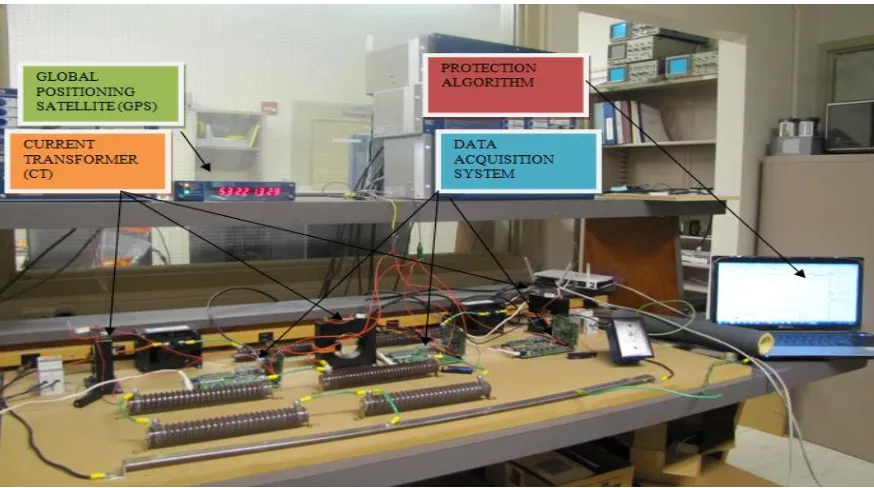
A prototype of the proposed protection system has been built and connected to the same test-bed. The prototype consists of the data acquisition systems (e.g., AMUs), which implements the digitizing and sampling task, the protection and communication program in the computer, a GPS clock that is used to synchronize the data sampling of AMUs and the associated Ethernet communication. The experimental view of the test-bed is shown in Fig. 9.
Figure 9. The prototype of the protection system on the test-bed
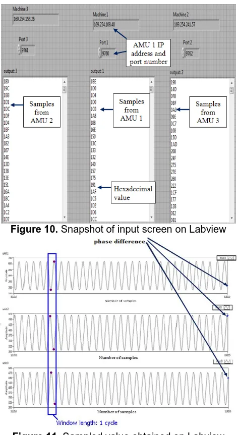
Figure 10 shows how the data is obtained by the protection program in the control panel. The data then goes to the TCP program, which extracts the data from the incoming TCP packets and converts the data (e.g., current value) from hexadecimal to decimal formats that can be executed by both the differential and overcurrent protection algorithms.
Figure 11 shows the output waveforms after the data conversion. It can be observed in Fig. 11 that a smooth A/D conversion is achieved from the three microcontroller outputs. The X-axis “Time” is plotted for the same sample points across all three microcontrollers. As the blue box depicted in Fig. 11, the phases of the three sine waveforms that sampled from the three microcontroller are not the same. Similarly, for the sampling at the right edge, the phase of the sine waveforms are not the same for the three microcontrollers either. This pattern is observed to continue for the entire period of observation. In short, the three microcontrollers are not time-synchronized.
The extensive testing results indicate that the performance is hindered by the mis-synchronization caused by the uncertain delay in Ethernet communications. For example, the mis-synchronization can be large enough, say 10 ms, to fail the instantaneous sample calculation of the differential algorithm.
When the waveforms are closely checked, the outputs from units 2 and 3 differ from each other by 1 ms, which is a difference acceptable to the differential protection algorithm. But unit 1 varies by 8 ms from unit 3 and 6 ms from unit 2, respectively. The reason of such mis-synchronization is due to the indeteministic TCP protocol
that takes slightly different times to transfer data from an AMU to the program through the Ethernet communication.
5.3. Performance of the primary protection
The differential protection unit is designed to calculate the instantaneous sampling values from the AMUs directly. However, the differential protection requires perfect synchronization among the instantaneous sampling points, which means that all the sampling values received at the differential units have to be exactly in the same time. The mis-synchronized data will result in incorrect trip signal generated by the differential protection algorithm.
As shown by the input data in Fig. 11, if we directly calculate the instantaneous sample values from different AMUs, the calculation result of the differential unit swings from 0.1 to 0.5 as time varies, as shown in Fig. 12, where 0.3 is the slope threshold. Normally, the calculation result of the differential unit shall be always less than 0.1, or close to zero. As a result, the protection system will generate a wrong trip signal every cycle even when the FREEDM system is under normal operation. Therefore, the differential protection system will not work properly.
protection program stays unchanged. The digital data points will be recorded until every packet completes its data transmission to the computer, as shown by the window in Fig. 11.
Figure 10. Snapshot of input screen on Labview
Figure 11. Sampled value obtained on Labview
program
Figure 12. Differential unit output with instantaneous samples’ calculation
Figure 13. Output of the differential unit with peak-to-peak samples’ calculation
Figure 14. Differential protection result
Figure 15. Overcurrent protection unit 1’s output during a fault
The microcontroller is programmed to send 17 samples in one packet, so each packet received from a microcontroller is one full cycle of the sine wave. There are two peaks, including the positive and negative half cycle, and a peak-to-peak value in every packet. Thus, the input of the differential unit is changed from the instantaneous samples to the samples of the peak-to-peak value in a cycle. Since the mis-synchronization in the TCP communication is around 10ms, which is less than a cycle (e.g., 16.7 ms for 60 Hz), the synchronization is achieved. The output of the differential algorithm with peak-to-peak input is presented in Fig. 13.
of the trip signal while the upper one in black is the peak-to-peak value of one AMU. Initially, the system is in normal condition. The peak-to-peak value is around 200. When a fault happens on the test-bed circuit, the peak-to-peak waveform rises to around 500 and the trip signal is generated. This confirms the successful operation of the primary protection by generating the trip signal correctly.
5.4. Performance of the backup protection
The overcurrent algorithm only calculates the value of current at an individual AMU, thus it is not affected by the mis-synchronization of time. In the event of a fault generated using the switch, the output of the overcurrent protection algorithm and the resulting trip signal (demonstrated as a DC signal) are shown in Fig. 15.
It can be clearly observed that the trip signal is generated a little later than 1 cycle but within 2 cycles, after the fault inception. This confirms the successful operation of the protection algorithm. Therefore, the overcurrent unit can provide the backup protection in case the primary one fails.
6. Conclusion
In this work, we propose a new protection system to solve the protection challenges in a smart grid with loop topology, with the following innovations:
First, the new system combines the advantages of the pilot differential and percentage differential protection.
Second, the new system replaces the conventional relays by digital data acquisition and real-time Ethernet to overcome the distance issue.
Third, the time-synchronization of the instantaneous current values among the AMUs is accomplished by using GPS clocks.
Fourth, in order to overcome the mis-synchronization caused by the Ethernet, we propose to use the peak-to-peak value as the input to the central computer.
We build a prototype of the new protection system and test it on a test-bed within the FREEDM System Center. We design a protection program that is implemented in Labview’s real-time environment and executed by the central computer on reception of the AMUs.
We demonstrate by experiments that the new protection system achieves a fast protection speed of less than 2 cycles (e.g., 33.4 ms, for 60 Hz).
Our future work would be investigating the deterministic communication protocols, which can further reduce the uncertain delay in the communication and deliver the data packets in a highly synchronized way.
Acknowledgements.
The authors would like to acknowledge the funding by NSF (Award number EEC-08212121) and thank all the people who helped during the development of the test-bed used in this work.
References
[1] FREEDM system centre. (2014). “About: FREEDM System”, available on www.freedm.ncsu.edu/
[2] Sathyanarayana, B., Heydt, G., Crow, M., and Meng, F. (2009) “Test Bed Evaluation of Future Power Distribution Systems with Renewable Resources for the FREEDM System,” In Proceedings of FREEDM System Center Annual Conference, Raleigh, NC, June,pp.27-33. [3] FREEDM center (2009) “FREEDM Systems Center First
Year Annual Report”, available on www.freedm.ncsu.edu/ [4] Steurer, M., Vodyakho, O., Neumayr, D., and etc. (2010)
“Development of Solid State Fault Isolation Devices for Future Power Electronic based Distribution Systems,” In
Proceedings of FREEDM System Center Annual Conference, Raleigh, NC, June,pp.16-21.
[5] Karady, G., Zhang, H., Zhang, M. and Guan, Y. “Concept of FREEDM Loop Line Fault Protection,” In Proceedings of FREEDM System Center Annual Conference, Raleigh, NC, June,pp.167-170.
[6] Fardanesh, B. and Richards, E. (1984) “Distribution System Protection with Decentralized Generation Introduced into the System,” IEEE Trans. on Industry Applications 20(1): 122 – 130.
[7] Chuang, A. and Schwaegerl, C. (2009) “Ancillary Services for Renewable Integration,” In Proceedings of Integration of Wide-Scale Renewable Resources Into the Power Delivery System, CIGRE/IEEE PES Joint Symposium, Calgary, AB, July, pp. 1-6.
[8] Thompson, M. (2011) “Percentage Restrained Differential, Percentage of What?,” In Proceedings of 64th Annual Conference for Protective Relay Engineers, College Station, TX, April, pp. 278-289.
[9] Wong, C., Lam, C., Lei, K., Lei, C and Han, Y. (2003) "Novel wavelet approach to current differential pilot relay protection", IEEE Transactions on Power Delivery 18(1): 20-25
[10] SEL inc, (2011), “SEL 387E Relay-Current Differential and Voltage Protection Relay,” available on www.selinc.com.
[11] Martin, K., Benmouyal, G., Adamiak, M., Begovic, M. and etc. (1998) “IEEE Standard for Synchrophasors for Power Systems,” IEEE Trans. on Power Delivery 13(1): 73-77. [12] Rindos, A., Woolet, S., Nicholson, L., and Vouk M. (1996)
“A Performance Evaluation of Emerging Ethernet Technologies: A Switched/High-Speed/Full-Duplex Ethernet and Ethernet LAN emulation over ATM,” In
Proceedings of the Southeastcon, Bringing together Education, Science and Technology, Tampa, FL, April,pp. 401-404.
[13] Beck, M. (2005) “Ethernet in the First Mile: The IEEE 802.3ah EFM Standard,” 1st ed. (New York: McGraw-Hill