R E S E A R C H
Open Access
Depth-image-based rendering with spatial and
temporal texture synthesis for 3DTV
Ming Xi
1,2, Liang-Hao Wang
1,2*, Qing-Qing Yang
1,2, Dong-Xiao Li
1,2and Ming Zhang
1,2Abstract
A depth-image-based rendering (DIBR) method with spatial and temporal texture synthesis is presented in this article. Theoretically, the DIBR algorithm can be used to generate arbitrary virtual views of the same scene in a
three-dimensional television system. But the disoccluded area, which is occluded in the original views and becomes visible in the virtual views, makes it very difficult to obtain high image quality in the extrapolated views. The proposed view synthesis method combines the temporally stationary scene information extracted from the input video and spatial texture in the current frame to fill the disoccluded areas in the virtual views. Firstly, the current texture image and a stationary scene image, which is extracted from the input video, are warped to the same virtual perspective position by the DIBR method. Then, the two virtual images are merged together to reduce the hole regions and maintain the temporal consistency of these areas. Finally, an oriented exemplar-based inpainting method is utilized to eliminate the remaining holes. Experimental results are shown to demonstrate the performance and advantage of the proposed method compared with other view synthesis methods.
Keywords: Virtual view synthesis, Three-dimensional television (3DTV), Depth-Image-Based Rendering (DIBR), Stationary scene extraction, Inpainting
1 Introduction
Year 2010 is considered to be the year of breakthrough for 3D video and 3D industry [1]. Numerous 3D films are pro-duced and released to the market. Stereo movies provide people stereo perceptions by showing two slightly differ-ent images of the same scene. Consumers can have immer-sive feelings by watching them in theaters with stereo eyeglasses. Disks and players of 3D Blu-ray standard have entered the home entertainment. The prosperity of 3D industry gives an important opportunity for three-dimensional television (3DTV) system, which is believed to be the next generation of television broadcasting after high-definition television. The concept of 3DTV system is defined by European project ATTEST [2] and developed by Morvan et al. [3] and Kubota et al. [4]. To improve the depth perception of users, autostereoscopic display tech-nology without any need of additional glasses is preferred in the display part of 3DTV. Autostereoscopic displays can
*Correspondence: wang [email protected]
1Institute of Information and Communication Engineering, Zhejiang University, Hangzhou, 310027, P.R. China
2Zhejiang Provincial Key Laboratory of Information Network Technology, Zhejiang University, Hangzhou, 310027, P.R. China
provide comfortable stereo parallax and smooth motion disparity by displaying multiview images of the same scene simultaneously. A simple approach is to capture, com-press, and transmit multiple views directly. The current multiview video coding standard [5,6] with high compres-sion efficiency, which exploits the spatial correlations of the neighboring views, is used to encode and decode the multiple video streams, generally more than eight views. But the transmission bandwidth cost remains a challeng-ing and unresolved problem. Meanwhile, it is commonly suggested that the future 3DTV systems should have com-pletely decoupled capture and display operations [7]. A proper abstract intermediate representation of the cap-tured data, video plus depth format, is proposed by Fehn [8] to achieve such a decoupled operation with an accept-able increment of bandwidth. The depth-image-based rendering (DIBR) [2] algorithm will be used to render multiple perspective views from the video plus depth data according to the requirement of autostereoscopic displays. Thus, the DIBR method has attracted much attention, and become a key technology of the 3DTV system [1].
The video plus depth data format consists of one texture color image and its corresponding perpixel dense depth
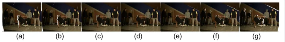
map. Theoretically, being provided with the intrinsic and extrinsic parameters of the virtual views, the DIBR algo-rithm can be used to synthesize any virtual perspective views from the video plus depth data. But there exists three problems [2], which are visibility, resampling, and disocclusion. Multiple pixels of the reference view may fall into the same position in the virtual image plane, which will cause the visibility problem. A Z-buffer algorithm [9] can solve this problem by recording the Z values and choosing the nearest pixel to the virtual camera plane. The phenomenon of an integer pixel position in the reference view image being projected to a subpixel position in the virtual view is called resampling problem, which can be coped with upsampling procedure or backwards warping with interpolation. The remaining disocclusion problem is the fact that some parts of the captured scene, which are occluded in the original views, become visible in the virtual views. It is caused by the lack of scene informa-tion occluded by the foreground objects in the original view position. As the distance from virtual view to refer-ence view increases, the disoccluded area becomes larger, as shown in Figure 1.
The disocclusion problem is considered to be the most significant and difficult one of the DIBR algorithm. It is well handled in the interpolation operation [10-13], but will become severe in the extrapolation situation, where the missing image information needs to be reconstructed by appropriate algorithms. Lots of algorithms have been developed to solve this problem, which can be divided into three categories.
The first is layered-depth-image (LDI) [14,15], which can achieve excellent rendering results by providing suf-ficient information of the scene. LDI data are composed of a number of color layers and their corresponding depth layers, which contain not only the texture and depth infor-mation of visible scene from the front view, but also that of the occluded regions. It is very simple to obtain high-quality multiview images from LDI data. However, the procedure of creating LDI is computationally complex and quite time-consuming. The transmission bandwidth of LDI data also increases drastically with the num-ber of layers. A simplified data format of LDI, which is called the “Declipse” format [16], is proposed by Philips
Corporation. The “Declipse” format data consist of fore-ground layer and backfore-ground layer. It presents the advan-tage to improve the rendering quality with a quite small overhead in terms of complexity and bitrate.
The second approach is called depth image preprocess-ing. To reduce the disoccluded areas in virtual views, low pass filter is applied to smooth the depth image. Fehn [2] uses a suitable Gaussian filter preprocessing the depth image to eliminate the disocclusions with the cost of slightly geometric distortions. An asymmetric smoothing method is proposed by Zhang and Tam [17]. By enlarg-ing the standard deviation and window size of Gaussian filter in vertical direction, the vertical structure distortion is reduced. The filtering effect is to smooth the sharp dis-continuities in the depth image, thus reducing the hole areas near object boundaries. A consequence of these algorithms is that the whole depth map has been modi-fied, which will severely blur the distance between scene objects in different depth layers. To cope with depth loss, different kinds of oriented filters [18-21] are designed with the same principle, i.e., smoothing the sharp edge in the depth image locally and keeping the depth of the other regions unchanged. The oriented filters can improve the image quality of the virtual views, but still induce geomet-ric distortion. Although the depth image preprocessing methods can be used to handle the disoccluded regions in the virtual views of small baseline, obvious geometric distortions will occur when the baseline is getting larger.
The third approach to filling the disoccluded areas is image completing techniques. This approach can be fur-ther classified into statistical-based methods, partial dif-ferential equations (PDE)-based methods, and exemplar-based methods. Statistical-exemplar-based methods [22-25] have good performance in pure texture synthesis applications, but fail to complete natural images with complex struc-ture. PDE-based methods [26-29], which are also called image inpainting methods, propagate linear structures into the disoccluded areas smoothly via diffusion. The dif-fusion process is simulated by the PDE of physical heat flow. Inpainting methods are suitable for removing small image artifacts, such as speckles, scratches, and over-laid texts. When the disocclusion is getting larger, the diffusion process will over-smooth the image and cause
visible blurring artifacts. Exemplar-based methods [30,31] fill the hole regions by copying patches with the simi-lar texture from the known neighborhood of the image. Criminisi et al. [30] use the exemplar-based method to remove objects from images. Komodakis and Tziritas [31] propose an efficient belief propagation method to obtain global optimization. Exemplar-based methods have been used for the case of video completion in [32,33]. Multi-ple frames are provided as the searching source of best match patch by Cheng et al. [34] to achieve temporal continuity. Exemplar-based methods have been the most powerful techniques for dealing with large disoccluded regions. Schmeing and Jiang [35] first obtain the back-ground information with a computed backback-ground model. But their approach cannot handle the uncovered areas caused by static foreground objects. For each virtual view, Ndjiki-Nya et al. [36] use a background sprite to update the texture and depth information of disoccluded areas. There are two major drawbacks of this method. One is the valuable background information of disocclusions, which cannot be reused during the generation of other virtual views. The other is the memory cost increases with the number of virtual views.
In this article, a new virtual view generation method with spatial and temporal texture synthesis is proposed. The structure information of the captured scene in the temporal domain is taken into account by maintaining an accumulated sprite of stationary scene. An oriented exemplar-based inpainting algorithm is applied to restore the rest disoccluded areas with background texture.
The remainder of this article is organized as follows. In Section 2, a brief description of the algorithm frame-work is given. The details of each processing modules are demonstrated in Sections 3, 4, 5, and 6. Experimen-tal results are compared with state-of-the-art methods in Section 7. The conclusions and future works can be found in Section 8.
2 System overview
The framework of proposed DIBR method with spatial and temporal texture synthesis is shown in Figure 2. The proposed method is divided into four main stages, i.e., stationary scene extraction, backward DIBR, merging operation, and oriented exemplar-based inpainting.
In the first stage, a sprite of stationary scene is main-tained throughout the view synthesis process, which stores the temporally accumulated structure and depth information of stationary image part. The Structural SIM-ilarity index (SSIM) [37] is utilized to distinguish the stationary scene from the moving foreground objects by combining the input depth images. For stationary scene, the SSIM index between adjacent frames is large, so the image part, which is stationary in both adjacent frames, can be extracted by using the SSIM index values. But
View N View N+1
Stationary Scene Extraction
Backward DIBR
Backward DIBR
Merge
Oriented Exemplar-Based
Inpainting
Extra. Inter.
Virtual View
Figure 2Flow diagram of the proposed virtual view synthesis method.First, the sprite of stationary scene is initialized with the first image frame of the input data. Next, each frame is compared with the sprite of stationary scene to extract more structure information. Then both the current frame and sprite of stationary scene are rendered to the same virtual view and merged together. Finally, the remaining disoccluded areas are filled by proposed oriented exemplar-based inpainting.
there still are some stationary scenes, which cannot be distinguished due to the occlusions of moving foreground objects. By considering the spatial relationship provided by the input depth maps, the texture information of these occluded stationary scenes can also be obtained. In the demonstration of our algorithm, the camera of input view is supposed to be still for simplicity. If the camera is moving, an additional camera tracking module needs to be inserted before stationary scene extraction stage to compensate the global motions, which is beyond the discussion in this article.
In the second stage, current frame and stationary scene sprite are warped to the same virtual perspective view by a backward DIBR method to tackle the visibility problem and resampling problem.
can take use of most of the scene information provided by the sprite of stationary scene.
After the merging operation, there still exists a few blank regions without pixel values. In the final stage, ori-ented exemplar-based inpainting approach is applied to fill the remaining holes by searching best matching exem-plar with background texture. Current virtual image is used as the searching source of best matching patch. The filling order of the inpainting method is steered from background structures to foreground objects.
Note that the proposed method only uses the sequence of color images and depth images from one captured view as the input data. If image data of another view are also provided, the switch in the framework can directly be shifted from the extrapolation mode to the interpolation mode without any changes of the framework.
3 Stationary scene extraction
The DIBR algorithm warps the original view to the vir-tual view position by projecting current pixels to points in real 3D space and re-projecting the 3D points to vir-tual image plane. Large disocclusions will appear in the discontinuous edges of depth map, which is the transi-tion place between foreground and background in texture image. The background image part occluded by fore-ground objects should be visible in the virtual views. But the occluded background information is lost during the procedure of recording a 3D scene by a 2D image. To solve this problem, the proposed stationary scene extrac-tion module tries to recover the lost background structure from video sequences. For a video captured by a fixed camera or a short cut of video, the image consists of mov-ing foreground objects and stationary background. The occluded background information in current image frame may appear in frames at other moments. If the informa-tion can effectively be used, the filling effect of disoccluded areas will be more convincing.
Stationary scene extraction algorithm keeps a global sprite throughout the view generation process to accumu-late structure and depth information of stationary scene in temporal direction. The global sprite of stationary scene is composed of two components: one is the texture image of stationary scene, denoted asCSS, the other is the depth
map of stationary scene, denoted asMSS.CSSandMSSare,
respectively, initialized with the first frame of the texture sequence and depth sequence of the original view. The initialization step is expressed as follows:
CSS(p)=It(p)
MSS(p)=Dt(p)
, t=0 (1)
wherep:(i,j)corresponds to the pixel of column coordi-nateiand row coordinatej.ItandDtrepresent the color
intensity frame and depth map frame of input original
view at timet, respectively.Dtis represented as an 8-bits
gray-scale image. The continuous depth range is quan-tized to 255 discrete depth values. The nearest object to the camera image sensor is assigned with 255 and the far-thest object is assigned with 1. Pixels with depth value 0 are denoted as holes. The transform formula between dis-crete depth level and actual distance in real scene can be found in [12].
After the initialization, a temporary sprite of stationary scene, denoted as TCSS andTMSS, is obtained between
each input image frameItand its previous frameIt−1to
extract the useful information of occluded background in It. For stationary scene, the SSIM index [37] between
adja-cent frames is large, so the image part, which is stationary in both adjacent frames, can be extracted by using the SSIM index values. For each pixelp:(i,j), a structure sim-ilarity indexpSSIM defined in [37] is calculated between
the corresponding square areasItandIt−1ofItandIt−1,
which takepas the center pixel andL×Las the window size. The SSIMpSSIMis calculated as follows
pSSIM =
(2μtμt−1+K1)(2σt(t−1)+K2)
(μ2 t+μ
2
t−1+K1)(σ 2
t+σ 2
t−1+K2)
(2)
whereμt,μt−1 represent the luminance mean value of It and It−1, respectively. σt and σt−1 represent the
luminance standard deviation of It and It−1. σt(t−1) denotes the luminance correlation coefficient betweenIt
andIt−1.K1andK2are constants. The value ofK1and
K2can be determined according to the research work in
[37]. The expressions of mean, standard deviation, and correlation coefficient can also be found in [37].
Then an arbiter with thresholdAis used to divide the pixels of input image frameItinto stationary partIsand
rest partIr. The classifier can be expressed as follows:
p∈Is, pSSIM≥A
p∈Ir, pSSIM<A
, p:(i,j)∈It. (3)
Is contains the stationary pixels with high SSIM value,
which can directly be used to update the same pixel posi-tions in TCSS. Ir are composed of three parts: the part
with changed luminance Plc, the relatively moving part
Prm, and the actually moving partPam.Plcrepresents the
areas with similarly scene structure and different lumi-nance which causes the decrease of SSIM value.Prmis the
region which is moving inIt−1and stationary in It. Pam
denotes the image part which is moving inItand
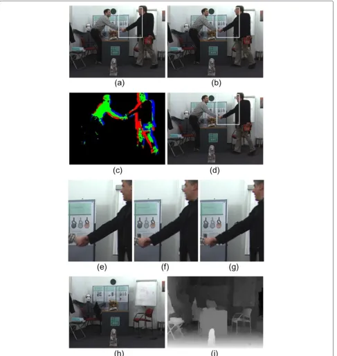
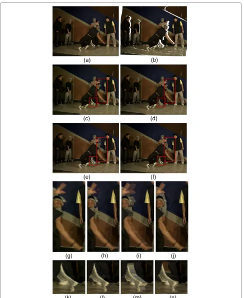
station-ary inIt−1. As shown in Figure 3c,Isbetween Figure 3a,b
is marked as black, the actually moving partPamis marked
as red, the region with changed luminancePlcis marked
as green, and the relatively moving area Prm is marked
as blue. The first two kinds Plc and Prm can be also
used to updateTCSSdirectly, whereas the third kindPam
regions ofIt−1will be used to updateTCSS. As shown in
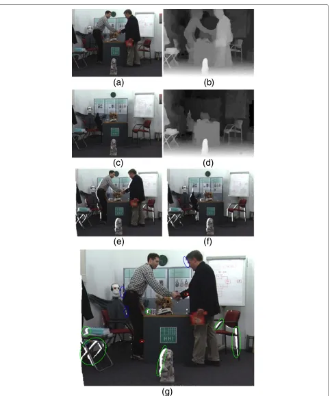
Figure 3e–g, the poster occluded by the men’s hands in Figure 3e and the white board behind the man in Figure 3f are all preserved in Figure 3g. Provided with the cor-responding depth map Dt and Dt−1, the three different
image parts are defined as follows.
⎧ ⎪ ⎪ ⎨ ⎪ ⎪ ⎩
p∈Plc, μDt −μDt−1≤T
p∈Prm, μDt −μDt−1<−T
p∈Pam, μDt −μDt−1>T
, p:(i,j)∈Ir (4)
where μDt and μDt−1, respectively, represent the average depth value of square areas in Dt andDt−1. The square
neighborhoods have the same window size L × L with SSIM computation in Equation (2) and take the coor-dinates of pixel p as center position. T is a constant threshold, which defines the acceptable range of depth fluctuation.|·|is the absolute function.
Then the information of stationary scene between two adjacent frames can be extracted by the following equation:
TCSS(p)=
It(p), p:(i,j)∈Is∪Plc∪Prm
It−1(p), p:(i,j)∈Pam
TMSS(p)=
Dt(p), p:(i,j)∈Is∪Plc∪Prm
Dt−1(p), p:(i,j)∈Pam
(5)
Finally, the temporary sprite of stationary scene (TCSS
andTMSS) is used to update the global sprite (CSS and
MSS). The update operation is described as follows.
Css(p)=
TCSS(p),μpTM−μ p
M≤T
CSS(p), otherwise
p:(i,j)∈CSS
Mss(p)=
TMSS(p),μpTM−μ p
M ≤T
MSS(p), otherwise
p:(i,j)∈MSS
(6)
where μpTM and μpM, respectively, represent the average depth value of square areas inTMSSandMSS. The square
neighborhoods have the same window size L × L with SSIM computation and take the coordinates of pixelpas center position.Tis the same constant threshold defined in Equation (4). Figure 3d shows TCSS of Figure 3b.
Figure 3h,i are CSS and MSS of Figure 3b, respectively.
Almost all the texture and depth information of stationary scene are restored in Figure 3h,i.
So far, the appeared background information in past frames is stored in CSS and MSS, which can be used
to partly solve the disocclusion problem of virtual view synthesis algorithm.
4 Backward DIBR
The backward DIBR method, which shares the same idea with the inverse warping method in [13], can efficiently eliminate the small cracks in virtual view caused by resam-pling problem in traditional DIBR process [2]. In general, the backward DIBR method can be divided into two steps: warping the depth map of the reference view to the vir-tual view position and generating the texture image of the virtual view.
In the backward DIBR method, Dt, is warped to
vir-tual perspective position. A two-pixel-wide region around background–foreground transitions is marked as unreli-able pixels. During the rendering process of depth map, the unreliable pixels will be skipped, because their depth values are inaccurate. There are four registers in each pixel q : (u,v) of virtual view, which are used to store the depth and distance of four nearest pixels projected from the reference image. The four registers of pixelqonly store rendered pixels from reference image whose distance toq is less than one pixel either in horizontal or vertical direc-tion.VDt, the depth map of virtual view, is calculated as
follows
V Dt(q)= ⎧ ⎪ ⎪ ⎨ ⎪ ⎪ ⎩
N(q)
k=1
λkDk,N(q) >0 and N(q)≤4
0, N(q)=0
(7)
where N(q) denotes the numbers of pixels warped to q, which satisfy the condition mentioned above. IfN(q)
is larger than 4, we sort the warped pixels by its depth value in large to small order and store the first four pix-els with larger depth.Dkis the depth value of stored pixel.
N(q) = 0 means there is no pixel that is projected to pixelq.λk represents the normalized weight factor with the combination of distance and depth, which is defined as
λk= Nρkωk
(q)
m=1ρmωm
,
N(q)
k=1
λk=1 (8)
where the weight factor of distance ωk is expressed as
Equation (9).(Uk,Vk)is the projected position of warped
pixel in virtual image plane.
ωk = 1
(Uk−u)2+(Vk−v)2
(9)
The weight factor of depthρkis expressed as
ρk=
1, Dk≥μND
0, Dk< μND
(10)
where μND is the average depth value of all the stored
warped pixels in pixelq.
The non-hole pixel(u,v)inVDtis reprojected to
texture image of virtual view by interpolation operation. The texture image of virtual viewVItis calculated by
V It(q)= ⎧ ⎪ ⎪ ⎪ ⎪ ⎪ ⎪ ⎨ ⎪ ⎪ ⎪ ⎪ ⎪ ⎪ ⎩ 4
n=1 θnIn
4
n=1 θn
, V Dt(q) >0
hole, V Dt(q)=0
(11)
where ‘hole’ flag means there is no warped pixel from the reference image. We set the hole pixels with a white color (R = 255, G = 255, B = 255).Inrepresents the color value
of pixel(xn,yn)whose distance to(Xuv,Yuv)is less than
one pixel either in horizontal or vertical direction.θnis the
weight factor of distance, which is expressed as
θn=
1
(Xuv−xn)2+(Yuv−yn)2
. (12)
The virtual depth map VMt projected from MSS and
the virtual texture image VCt projected from CSS can
be obtained by the same backward DIBR method. Two results of our backward DIBR algorithm are given in Figure 4e,f.
5 Merging operation
To efficiently use the structure information inCSS, the two
virtual texture images (VItandVCt) need to be merged
together. The merged virtual image and its depth map are denoted asMIt andMDt, respectively. The virtual view
image VIt is dominated in the merging process.
Avail-able background information in VCt is used to fill the
blank areas inVIt. There may be holes in both foreground
and background due to the inaccuracy of depth map, as shown in Figure 4e. We do the merging operation care-fully to avoid filling holes in foreground with background structures.
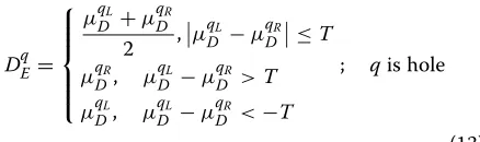
First, an estimated depth valueDqE is obtained for each hole pixelq : (u,v) in VIt. As mentioned in Section 3,
the hole regions of virtual view are lacking of background information. When q locates between background and foreground, we choose the small depth value of back-ground scene as estimation and the average depth other-wise. The estimation is defined as
DqE=
⎧ ⎪ ⎪ ⎪ ⎨ ⎪ ⎪ ⎪ ⎩
μqL
D +μ
qR D
2 ,μ
qL
D −μ
qR
D≤T
μqR
D, μ
qL
D −μ
qR D >T μqDL, μDqL−μqDR <−T
; qis hole
(13)
whereqLandqRrepresent the first left and first right
non-hole pixel in horizontal column, respectively.μqL
D andμ
qR D
represent the average depth of theK×Kwindows which
takeqLandqRas the center pixels inVDt.T is the same
constant defined in Equation (4).
Then the merging operation is executed as follows.
MIt(q)= ⎧ ⎪ ⎪ ⎪ ⎪ ⎨ ⎪ ⎪ ⎪ ⎪ ⎩
V It(q), V It(q)is non-hole
V Ct(q), V It(q)is hole andV Ct(q)is
non-hole andV Mt(q)−DqE≤F
hole, otherwise
(14)
where non-hole flag means there exists a meaningful value in this pixel position. The second condition in Equation (14) defines the situation, i.e., the pixelq is hole inVIt,
but meaningful pixel with available background texture in VCt. This condition ensures that the holes in foreground
objects will not be filled with the accumulated background information in VCt. F represents the acceptable range
of depth fluctuation in merging operation. In Figure 4g, the available texture of stationary background scene in Figure 4f is merged with the virtual image (Figure 4e) ren-dered from original view and the hole areas in foreground objects are reserved. The corresponding depth value of each non-hole pixel in merged virtual viewMItis stored in
MDt, and the depth value of each hole pixel is set to zero.
6 Oriented exemplar-based inpainting
The merging operation can solve the disocclusion prob-lem partly, because the useful background information in CSSandMSSis limited. There still exist hole areas in the
merged virtual viewMIt, which are divided into two kinds:
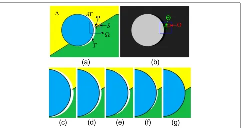
the foreground holes caused by inaccurate depth map and the blank areas caused by occlusion in original view. The image part with known pixels is defined by , and the remaining hole area is denoted as . The border of hole area is defined as∂ , as shown in Figure 5a.
(a)
(b)
(c)
(d)
(e)
(f)
(g)
Ο
Θ
Γ
Λ
Ω
δ Γ
Ψ
S
(a)
(b)
(c)
(d)
(e)
(f)
(g)
Figure 5Effect of proposed oriented exemplar-based inpainting algorithm on a synthetic image.(a)A synthetic image of virtual view with disoccluded areas, which are represented by white color.(b)The corresponding depth map of(a). The black color indicates the hole areas in depth map.(c–g)The magnified result of proposed oriented exemplar-based inpainting algorithm afterNiterations:(c)N=2,(d)N=70,(e)N=77,(f)
N=145, and(g)N=196. The patch size of the oriented exemplar-based inpainting algorithm is set to 15×15, and the search window size is 15×15.
calculation of the priority term and the energy function, both of which are used for the best exemplar searching procedure.
The modified priority term is defined as
P(h)=C(h)D(h)+de(h), h∈δ (15)
wherede(h)represents the depth term. The definition of C(h)and D(h) is the same as Criminisi’s approach, and their expressions can be found in [30]. The depth term is expressed as follows.
de(h)=
Q, hnearto BG
0, hnearto FG, h∈δ (16)
where BG and FG represent the background areas and foreground objects, respectively. Qis a constant, which should be no less than the maximum of the product of C(h)andD(h). We setQ = 256 in our framework. The new priority term will steer the filling order from back-ground to foreback-ground and keep the advantage of linear structure propagation.
Letrdenote the pixel with maximum priority in∂ . The J×Jsamples patch, which takesras center, is defined as
. A square area aroundrwithW×Wsamples is defined to be the searching area. Then the oriented exemplar-based inpainting algorithm needs to search for the best match patchS in, which has the most similar texture
with. The center ofSis denoted ass. The correspond-ing depth areas of andSare represented byand O, respectively.
The energy function combining the depth cue is expressed as follows.
E=
m∈k
(m)−S(m)2
+β m∈k
(m)−O(m)2+γμk−μuO2
(17)
wherekdenotes the position set of known pixels in the filling target patch. The position set of hole pixels inis represented byu:u=−k.(m)andS(m)denote
the pixel value of pixel positionminandS, respectively.
(m)and O(m)represent the depth value of pixel posi-tionminand O, respectively.βis a constant, which is the weighting factor for the depth values of correspond-ing pixels withkin.μkrepresents the average depth value of the corresponding pixels withkin.μuO
repre-sents the average depth value of the corresponding pixels withuin O.μkandμuOare defined as
μk= m∈k
(m)/|k|, μuO= m∈u
O(m)/|u|
where|u|denotes the area ofu.γ is the penalizing
fac-tor for the candidate patches with foreground texture.γ is an adaptive parameter related to the area ofk, denoted
as|k|. Thenγ is calculated as
γ =
0, μuO−μk≤T
10|k|, otherwise (19)
whereTis a constant as defined in Equation (4).
The best match block in the searching areais obtained by minimizing the energy cost function (17). The first term in energy function (17) represents the texture differ-ence between the known pixels in target patchand the corresponding pixels in match patchS. In our approach, only the luminance component is considered. The sec-ond term in (17) indicates the depth similarity, which has lower importance than the first texture term. The third term is a penalization term. If there exist pixels of fore-ground objects in the corresponding area ofu inS, the penalization term will become larger. The likelihood of selecting patches with foreground pixels is greatly reduced by adding the penalization term. According to the defini-tion of the energy funcdefini-tion, the patches of the background scene, which contain similar texture and depth struc-ture with the target block, will be selected to restore the missing information of the disoccluded image areas. We applied our oriented exemplar-based inpainting method to synthesize the missing texture information of disoc-cluded area in Figure 5a. The blank region is filled from background scene to foreground objects, and the linear structure is propagated into the hole in an appropriate way (see Figure 5c–g).
7 Methods
To evaluate the performance of the proposed method, we compare our approach with other methods, including the MPEG view synthesis reference software (VSRS, version 3.5) [38], the depth-based inpainting method in [29], and the Asymmetric Gaussian filtering method of Zhang and Tam [17].
Our experiments are carried out on three test sequences: “Book arrival”, “Breakdancers”, and “Ballet”. These sequences have 100 frames and a resolution of 1024 × 768 samples. Multiple video plus depth data from different camera views are available. “Book arrival” sequence is captured by a parallel camera array and the others are obtained by a toed-in camera array. The baseline between two adjacent cameras is approximately 6.5 cm for “Book arrival” sequence and 20 cm for the other two sequences.
The parameter values used in our proposed algorithm is summarized in Table 1. The optimized parameters are used for MEPG method (VSRS 3.5). For Asymmetric Gaussian filtering method, we utilize strong smoothing
Table 1 Parameter values used in proposed method
Parameter L A T K F J W β
Value 19 0.7 3 5 8 9 15 0.5
parameters to eliminate the disoccluded areas caused by large camera baseline. We set the horizontal and verti-cal standard deviations of the Gaussian kernel to 20 and 60, respectively. The filter window sizes are set to 61 samples horizontally and 193 samples vertically. In the experiments, the Asymmetric Gaussian filtering method and the depth-based inpainting method employ the back-ward DIBR approach proposed in Section 4 to handle the visibility and resampling problems, just the same as our proposed method.
7.1 Subjective evaluation
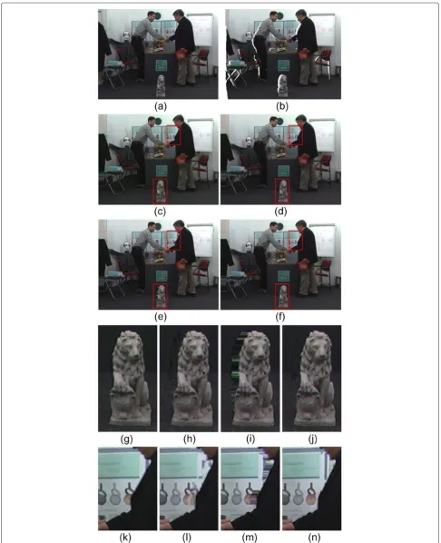
The view synthesis results of these three test video sequences are shown in Figures 6, 7, and 8. All of the four presented approaches can handle the visibility and resampling problems and fill the disoccluded areas in vir-tual view. Our proposed algorithm has the best subjective effects compared to the others three methods.
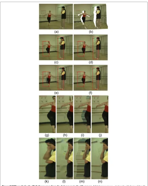
The Asymmetric Gaussian filtering method causes noticeable geometric distortions. The vertical structure is curved in Figures 6c and 7c. The foreground objects become fat, as shown in Figures 6k and 7g,k. This method will slightly shift the object away from its correct position (see Figure 6g), which will reduce the disparity between reference image and virtual image and decrease the 3D feelings. For the purpose of autostereoscopic display, although the visual quality of Figure 6g is still pleasant, the depth perception of the scene is distorted due to these shifts. The distorted stereo display will make people fill uncomfortable and arouse visual fatigues. The depth-based inpainting method can restore the blank areas with color of background pixels, but induce severe blurring artifacts (see Figures 6l, 7h,l, and 8h) and some color bleeding defects (see Figures 7h,l and 8h). The filling results are very uncomfortable for visual experience. The VSRS method will lead to significant horizontal structure artifacts (as shown in Figures 6i,m, 7i,m, and 8i,m) and decrease the visual quality greatly.
to the wall in Figure 8b, it is difficult to distinct the leg from the wall. In Figure 8n, our approach wrongly fill the hole with texture of the wall. Another important advan-tage of our approach is the temporary texture consistency of the filled disoccluded regions. For disoccluded areas caused by moving foreground objects, the missing texture is recovered from other frames. The true texture informa-tion in other frames is extracted and used to restore the hole areas. To demonstrate the consistency in temporal direction, a series of magnified virtual image subsection for “Ballet” sequence is shown in Figure 9. The disoc-cluded regions around the woman of adjacent frames are
restored by the same true background structure, then the texture of filled image areas maintains consistent in time direction.
7.2 Objective comparison
We adopt peak-signal-to-noise ratio (PSNR) and SSIM [37] to compare the performance of proposed approach with the other three methods.
For every test case of each sequence, the PSNR and SSIM values are calculated for the whole image region of every virtual image frame. The mean values of PSNR
Table 2 PSNR and SSIM results
Seq. Camera PSNR (dB) SSIM
VSRS Depth-based Asym. VSRS Depth-based Asym.
Prop. 3.5 inpainting filter Prop. 3.5 inpainting filter
[38] [29] [17] [38] [29] [17]
Book arrival 8→9 32.91 32.85 32.69 28.85 0.9814 0.9803 0.9798 0.9500
10→9 32.12 31.55 32.03 28.24 0.9817 0.9766 0.9811 0.9465
8→10 29.74 29.50 29.53 28.85 0.9672 0.9647 0.9645 0.8876
10→8 28.92 28.57 28.79 25.00 0.9684 0.9628 0.9660 0.8909
Break dancers 4→3 31.91 30.13 31.45 26.56 0.9470 0.9323 0.9440 0.8832
3→4 31.94 29.67 31.78 26.70 0.9518 0.9357 0.9500 0.8848
5→4 32.58 28.74 32.06 27.16 0.9532 0.9340 0.9503 0.8867
5→6 32.47 31.51 32.12 26.59 0.9503 0.9441 0.9482 0.8876
Ballet 3→4 30.10 28.20 29.63 22.58 0.9388 0.9111 0.9288 0.8280
5→4 31.91 26.87 31.85 23.28 0.9436 0.9151 0.9403 0.8304
5→3 27.74 24.41 25.92 20.17 0.8884 0.8575 0.8820 0.7517
3→5 27.38 25.98 27.10 20.82 0.8799 0.8447 0.8683 0.7489
This table shows the PSNR and SSIM values of four view synthesis methods. The best results are highlighted with boldface type.
and SSIM for each test case are stored in Table 2 and the best results are highlighted with boldface type. The “Cam-era” column indicates camera configuration of virtual view generation, i.e., “8→9” means synthesizing virtual view of the 9th camera’s perspective position from the 8th camera. From Table 2, we can observe that among these four methods the proposed framework has the best PSNR and SSIM performance for both the parallel and toed-in camera configuration. The Asymmetric Gaussian filter-ing method gets the lowest PSNR and SSIM values due to the geometric distortion. For the four test cases of “Book arrival” sequence, the baselines between the virtual view and reference view are small (6.5–13 cm). Because the holes around image boundary occupy great percent-age of the whole disocclusions (see Figure 6b), the PSNR and SSIM gains of our proposed framework are small, i.e., 0.09–0.22 dB for PSNR and 0.0006–0.0027 for SSIM compared to depth-based inpainting method. For the test cases of “Breakdancers” and “Ballet” with large base-line (20–40 cm), our proposed approach obtains larger PSNR and SSIM gains compared to depth-based inpaint-ing method, i.e., 0.16–1.82 dB for PSNR and 0.0018– 0.0116 for SSIM. There are two important reasons for the improvements of PSNR and SSIM in our proposed framework. One is the available structure information from the stationary scene sprite; the other is the oriented exemplar-based inpainting process with reasonable filling orders. Figure 10 shows the PSNR and SSIM curves for
two test cases. One is the virtual view of “Ballet” sequence, which is generated from the 3nd camera to the 4th camera. The other is the virtual view of “Breakdancers” sequence, which is generated from the 5th camera to the 4th camera.
27.50 28.00 28.50 29.00 29.50 30.00 30.50 31.00
0 10 20 30 40 50 60 70 80 90
PSNR(dB)
Frame number Ballet from camera 3 to camera 4
Proposed method VSRS Depth-based inpainting
26.00 27.00 28.00 29.00 30.00 31.00 32.00 33.00 34.00
0 10 20 30 40 50 60 70 80 90
PSNR(dB)
Frame number
Breakdancers from camera 5 to camera 4
Proposed method VSRS Depth-based inpainting
(a)
0.90 0.91 0.92 0.93 0.94 0.95
0 10 20 30 40 50 60 70 80 90
SSIM
Frame number Ballet from camera 3 to camera 4
Proposed method VSRS Depth-based inpainting
0.92 0.93 0.94 0.95 0.96 0.97
0 10 20 30 40 50 60 70 80 90
SSIM
Frame number
Breakdancers from camera 5 to camera 4
Proposed method VSRS Depth-based inpainting
(c)
(b)
(d)
Figure 10PSNR and SSIM curves for “Ballet” and “Breakdancers” sequences.(a)PSNR curve of “Ballet” from the 3rd camera to the 4th camera. (b)PSNR curve of “Breakdancers” from the 5th camera to the 4th camera.(c)SSIM curve of “Ballet” from the 3rd camera to the 4th camera.(d)SSIM curve of “Breakdancers” from the 5th camera to the 4th camera.
Figure 11The PSNR curves for a local area of “Book arrival” sequence.The concerned local area is the same subsection shown in Figure 6n. The virtual view is the 10th camera position generated from the 8th camera position.
7.3 Execution time
We implement these four algorithms in C language on a workstation of DELL Corporation and evaluate the run-time costs, as summarized in Table 3. The execution run-time of each step in proposed framework is given in Table 4.
Table 3 Execution time comparison
Seq. Runtime (s/frame)
Prop. VSRS 3.5 Depth-based Asym. filter [38] inpainting [29] [17]
Book arrival 12.53 1.50 136.93 2.11
Break dancers 11.89 3.92 138.74 1.65
Ballet 31.02 5.32 190.78 3.00
Table 4 Execution time of proposed framework
Seq. Runtime (s/frame)
BG extraction Backward DIBR + Merge
Oriented inpainting
Total
Book arrival 3.01 3.50 5.85 12.53
Break dancers 3.01 2.89 5.99 11.89
The workstation is equipped with an Intel 2.93-GHz Xeon quad-core CPU and 4-GB DDR2 RAM.
The runtime costs of Asymmetric Gaussian filtering and MPEG method are within 10 seconds per frame. The depth-based inpainting algorithm spends more than 2 min due to the time-consuming iteration operation. The pro-posed approach takes about 20 s to generate virtual view for each frame. The oriented exemplar-based inpainting process takes most of the time cost for our approach, about 50–80%, as shown in Table 4. The execution time of the oriented exemplar-based inpainting algorithm is depended on the size of disoccluded areas, the image patch size, and the size of searching window. For “Bal-let” sequence, because the area of hole regions is larger than the other two test sequences (cf. Figures 7b, 6b, and 8b), the runtime cost increases about 2 times. The addi-tional time cost is acceptable for the improvement in the objective and subjective qualities of virtual view image.
8 Conclusion and future work
This article presents a novel DIBR method combined with spatial and temporal texture synthesis. By maintaining a sprite of stationary scene of the original sequence, the use-ful structure information can be adopted to restore the missing texture of disocclusions in virtual view images. The remaining disoccluded areas are restored by pro-posed oriented exemplar-based inpainting approach. The oriented exemplar-based inpainting method fills the rest hole areas from background to foreground and propa-gates the structure and texture into the blank regions in an appropriate way. Combining these two algorithms, the proposed DIBR method solved the disocclusion problem well and achieved the spatial and temporal consistency. These features make the proposed approach very suitable for extrapolation of virtual view synthesis. Meanwhile, the proposed framework has the flexibility of shifting to the interpolation operation. Theoretical analysis and experimental results show that the proposed method out-performs state-of-the-art view synthesis methods. The increase of runtime cost is moderate and acceptable. Our future work will focus on the research of camera track-ing and motion compensation to extend our proposed method to the situation with moving cameras.
Abbreviations
3DTV: three-dimensional television; DIBR: depth-image-based rendering; LDI: layered-depth-image; PDE: partial differential equations; PSNR:
peak-signal-to-noise ratio; SSIM: structural similarity index; VSRS: view synthesis reference software.
Competing interests
The authors declare that they have no competing interests.
Acknowledgements
Ming Xi would like to thank Yin Zhao for his discussion and suggestion about the backward DIBR algorithm. Ming Xi also would like to thank Menno Wildeboer and Masayuki Tanimoto for their kindly help with the
implementations. The authors would like to thank the Interactive Visual Media Group at Microsoft Research and the Fraunhofer Institute for
Telecommunications-Heinrich Hertz Institute for providing the “Breakdancers”, “Ballet”, and “Book arrival” sequences, respectively. This study was supported in part by the National Natural Science Foundation of China (Grant nos. 60802013, 61072081, 61271338), the National High Technology Research and Development Program (863) of China (Grant no. 2012AA011505), the National Science and Technology Major Project of the Ministry of Science and Technology of China (Grant no. 2009ZX01033-001-007), Key Science and Technology Innovation Team of Zhejiang Province, China (Grant no. 2009R50003) and China Postdoctoral Science Foundation (Grant no. 20110491804, 2012T50545).
Received: 27 July 2012 Accepted: 23 November 2012 Published: 11 February 2013
References
1. A Smolic, P Kauff, S Knorr, A Hornung, M Kunter, M Muller, M Lang, Three-dimensional video postproduction and processing. Proc. IEEE.
99(4), 607–625 (2011)
2. C Fehn, inProceedings of SPIE Stereoscopic Displays and Virtual Reality
Systems XI, vol. 5291. Depth-image-based rendering (DIBR), compression,
and transmission for a new approach on 3D-TV (San Jose, CA, USA, 2004), pp. 93–104
3. Y Morvan, D Farin, PH de With, System architecture for free-viewpoint video and 3D-TV. IEEE Trans. Consum. Electron.54(2), 925–932 (2008) 4. A Kubota, A Smolic, M Magnor, M Tanimoto, T Chen, C Zhang, Multiview
imaging and 3DTV. IEEE Signal Process. Mag.24(6), 10–21 (2007) 5. A Smolic, K Mueller, N Stefanoski, J Ostermann, A Gotchev, G Akar, G
Triantafyllidis, A Koz, Coding algorithms for 3DTV—a survey. IEEE Trans. Circuits Syst. Video Technol.17(11), 1606–1621 (2007)
6. P Merkle, A Smolic, K Muller, T Wiegand, Efficient prediction structures for multiview video coding. IEEE Trans. Circuits Syst. Video Technol.
17(11), 1461–1473 (2007)
7. L Onural, T Sikora, Introduction to the special section on 3DTV. IEEE Trans. Circuits Syst. Video Technol.17(11), 1566–1567 (2007)
8. C Fehn, inProceedings of the Visualization, Imaging, and Image Processing, vol. 3. A 3D-TV approach using depth-image-based rendering (DIBR) (ACTA Press, Benalmadena, Spain, 2003), pp. 482–487
9. N Greene, M Kass, G Miller, inProceedings of the 20th annual conference on
Computer graphics and interactive techniques. Hierarchical Z-buffer
visibility (ACM Press, CA, USA, 1993), pp. 231–238
10. C Zitnick, S Kang, M Uyttendaele, S Winder, R Szeliski, High-quality video view interpolation using a layered representation. ACM Trans. Graph. (TOG).23(3), 600–608 (2004)
11. A Smolic, K Muller, K Dix, P Merkle, P Kauff, T Wiegand, in15th IEEE
International Conference on Image Processing. Intermediate view
interpolation based on multiview video plus depth for advanced 3D video systems. (San Diego, CA, USA, 12–15 October 2008) pp. 2448–2451 12. Y Mori, N Fukushima, T Yendo, T Fujii, M Tanimoto, View generation with
3D warping using depth information for FTV. Signal Process.: Image Commun.24(1–2), 65–72 (2009)
13. S Zinger, L Do, et al., Free-viewpoint depth image based rendering. J. Visu. Commun. Image Represent.21(5–6), 533–541 (2010)
14. J Shade, S Gortler, L He, R Szeliski, inin Proceedings of the 25th Annual
Conference on Computer Graphics and Interactive Techniques. Layered
depth images (ACM, Orlando, FL, USA, 1998), pp. 231–242
15. S Yoon, Y Ho, Multiple color and depth video coding using a hierarchical representation. IEEE Trans. Circuits Syst. Video Technol.
17(11), 1450–1460 (2007)
16. Comparative study and recommendations. http://www.3d4you.eu/ 17. L Zhang, W Tam, Stereoscopic image generation based on depth images
for 3D TV. IEEE Trans. Broadcast.51(2), 191–199 (2005)
18. W Chen, Y Chang, S Lin, L Ding, L Chen, inIEEE International Conference on
Multimedia and Expo. Efficient depth image based rendering with edge
dependent depth filter and interpolation. (Amsterdam, Netherlands, 6 July 2005) pp. 1314–1317
19. I Daribo, C Tillier, B Pesquet-Popescu, inIEEE 9th Workshop on Multimedia
Signal Processing. Distance dependent depth filtering in 3D warping for
20. W Wang, L Huo, W Zeng, Q Huang, W Gao, inIEEE International
Symposium on Intelligent Signal Processing and Communication Systems.
Depth image segmentation for improved virtual view image quality in 3-DTV. (Xiamen, China, 28 November–1 December 2007) pp. 300–303 21. L Wang, X Huang, M Xi, D Li, M Zhang, An asymmetric edge adaptive filter
for depth generation and hole filling in 3DTV. IEEE Trans. Broadcast.56(3), 425–431 (2010)
22. D Heeger, J Bergen, inProceedings of the 22nd Annual Conference on
Computer Graphics and Interactive Techniques. Pyramid-based texture
analysis/synthesis (ACM, Los Angeles, CA, USA, 1995), pp. 229–238 23. Bonet De J, inProceedings of the 24th Annual Conference on Computer
Graphics and Interactive Techniques. Multiresolution sampling procedure
for analysis and synthesis of texture images (ACM Press/Addison-Wesley Publishing Co., Los Angeles, CA, USA, 1997), pp. 361–368
24. J Portilla, E Simoncelli, A parametric texture model based on joint statistics of complex wavelet coefficients. Int. J. Comput. Vis.40, 49–70 (2000) 25. G Doretto, A Chiuso, Y Wu, S Soatto, Dynamic textures. Int. J. Comput. Vis.
51(2), 91–109 (2003)
26. M Bertalmio, G Sapiro, V Caselles, C Ballester, inProceedings of the 27th
annual conference on Computer graphics and interactive techniques. Image
inpainting (ACM Press/Addison-Wesley Publishing Co., New Orleans, LA, USA, 2000), pp. 417–424
27. M Bertalmio, L Vese, G Sapiro, S Osher, Simultaneous structure and texture image inpainting. IEEE Trans. Image Process.12(8), 882–889 (2003) 28. T Chan, J Shen, Nontexture inpainting by curvature-driven diffusions. J.
Vis. Commun. Image Represent.12(4), 436–449 (2001)
29. K Oh, S Yea, Y Ho, inIEEE Proceedings of Picture Coding Symposium. Hole filling method using depth based in-painting for view synthesis in free viewpoint television and 3-d video. (Chicago, IL, USA, 6–8 May 2009) pp. 1–4
30. A Criminisi, P P´erez, K Toyama, Region filling and object removal by exemplar-based image inpainting. IEEE Trans. Image Process.
13(9), 1200–1212 (2004)
31. N Komodakis, G Tziritas, Image completion using efficient belief propagation via priority scheduling and dynamic pruning. IEEE Trans. Image Process.16(11), 2649–2661 (2007)
32. K Patwardhan, G Sapiro, M Bertalm´ıo, Video inpainting under constrained camera motion. IEEE Trans. Image Process.16(2), 545–553 (2007) 33. T Shih, N Tang, J Hwang, Exemplar-based video inpainting without ghost
shadow artifacts by maintaining temporal continuity. IEEE Trans. Circuits Syst. Video Technol.19(3), 347–360 (2009)
34. C Cheng, S Lin, S Lai, Spatio-temporally consistent novel view synthesis algorithm from video-plus-depth sequences for autostereoscopic displays. IEEE Trans. Broadcast.57(2), 523 (2011)
35. M Schmeing, X Jiang, inIEEE 3DTV-Conference: The True Vision-Capture,
Transmission and Display of 3D Video (3DTV-CON). Depth image based
rendering: a faithful approach for the disocclusion problem (Tampere, Finland, 7), pp. 1–4
36. P Ndjiki-Nya, M Koppel, D Doshkov, H Lakshman, P Merkle, K Muller, T Wiegand, Depth image-based rendering with advanced texture synthesis for 3-D video. IEEE Trans. Multimed.13(3), 453–465 (2011)
37. Z Wang, A Bovik, H Sheikh, E Simoncelli, Image quality assessment: from error visibility to structural similarity. IEEE Trans. Image Process.
13(4), 600–612 (2004)
38. M Tanimoto, T Fujii, K Suzuki, View synthesis algorithm in view synthesis reference software 2.0 (VSRS2. 0) ISO/IEC JTC1/SC29/WG11 (2008)
doi:10.1186/1687-5281-2013-9
Cite this article as:Xiet al.:Depth-image-based rendering with spatial and temporal texture synthesis for 3DTV.EURASIP Journal on Image and Video Processing20132013:9.
Submit your manuscript to a
journal and benefi t from:
7Convenient online submission 7Rigorous peer review
7Immediate publication on acceptance 7Open access: articles freely available online 7High visibility within the fi eld
7Retaining the copyright to your article