ORIGINAL ARTICLE
Takafumi Nakagawa · Masamitsu Ohta Takahiro Tsuchimoto · Naohito Kawai
Collapsing process simulations of timber structures under dynamic loading
III: numerical simulations of real-size wooden houses
Abstract In this study, we developed a new analysis method
that enables numerical simulations of the collapse process of real-size wooden houses and evaluated the accuracy thereof by carrying out numerical simulations by shaking table tests. The distinct element method was adopted as the basic theory of our numerical analysis. This research is the fi rst approach in which the extended distinct element method was used for Japanese timber post-and-beam con-struction. The size of the analysis model is a 5.5 m × 5.5 m, two-story real-size wooden house. The three analytical models were developed in terms of the strength of exterior mortar walls. The simulation results were compared with the shaking table test results. One of the collapsing pro-cesses of the numerical simulation corresponds well to the experiment results. Assessment of the possibility of collapse for real-size wooden houses was determined to be possible using our newly developed numerical analysis method.
Key words Numerical analysis · Distinct element method ·
Shaking table test · Post-and-beam construction
T. Nakagawa (*)
Department of Building Materials and Components, Building Research Institute, 1 Tachihara, Tsukuba 305-0802, Japan Tel. +81-29-864-6625; Fax +81-29-864-6772
e-mail: [email protected]
M. Ohta
Graduate School of Agricultural and Life Sciences, The University of Tokyo, Tokyo 113-8657, Japan
T. Tsuchimoto
National Institute for Land and Infrastructure Management, Tsukuba 305-0802, Japan
N. Kawai
Department of Structural Engineering, Building Research Institute, Tsukuba 305-0802, Japan
Part of this report was presented at the 10th World Conference on Timber Engineering, Miyazaki, Japan, July 2008
Introduction
To prevent casualties during a large earthquake, prelimi-nary safety assessment of residential houses is one of the most important measures. During the Great Hanshin– Awaji Earthquake (also referred to as the 1995 Kobe Earth-quake), wooden houses without suffi cient seismic capacity were heavily damaged, and studies on the seismic perfor-mance of wooden houses have been actively conducted. To investigate the safety of wooden houses during large earth-quakes, it is important to assess the limit status and under-stand the possibility of collapse. Although the shaking table test is the most effective solution for this issue, a large cost is required, and experiments on the variety of specifi cations of wooden houses may be impossible.
A numerical analysis by computer simulation is an effec-tive way to assess the seismic performance of structures as an alternative to shaking table tests, and professionals use such analysis methods for structural design in practice. In advanced structural engineering research fi elds, computer simulations have been developed to solve questions about unknown physical phenomena or unknown structural systems. However, it is diffi cult to simulate the collapsing process by the commonly used calculating software, because the collapsing behavior includes large deformation of struc-tural elements and consideration of material nonlinearity, and geometric nonlinearity is needed for numerical calcula-tions. Furthermore, the safety limit of wooden houses is defi ned by the Japanese building code and recent research,1 but the actual collapse of conventional Japanese wooden houses occurs in a very large deformation region, from 1/10 to 1/3 rad story drift.2,3
Consideration of very strong nonlin-earity is needed to pursue the collapsing mechanism by numerical analysis. There are few analysis methods that are able to calculate this strong nonlinearity, including collapse behavior in the structural engineering fi eld.4
In our previous study,5,6 we developed a new simulation method based on the extended distinct element method (EDEM). We performed trial simulations for some timber structures, and our calculating method turned out to be
useful for collapsing process analysis of wooden houses. On the other hand, the models in our previous study were simple shear walls, so investigation of analysis for real-size house models was needed.
In this article, we have improved our previous calculat-ing program for the three-dimensional frame analyses. It is important in the collapsing process simulation to consider the P-Δ effect by structure weight and the twisting move-ment caused by the eccentricity of confi guration of the shear walls. Our analysis automatically incorporates the P-Δ effect and twist movement. To verify our numerical analy-sis, we carried out collapsing process simulations for real-size wooden houses that were used in real shaking table tests.
Theory
Extended distinct element method
In this analysis, we used the extended distinct element method (EDEM) as a basic theory. A detailed explanation of EDEM was given in our previous papers.5,6
EDEM is a noncontinuum analyzing method, so large deformation analysis of the fracture developing processes is possible. Furthermore, EDEM has advantages in terms of calculation cost, as it requires the calculation of equilibrium force equa-tions with adjacent elements only. Through this advantage, the calculation for analysis models with several tens of thou-sands of degrees of freedom can be carried out relatively easily by ordinary personal computers.
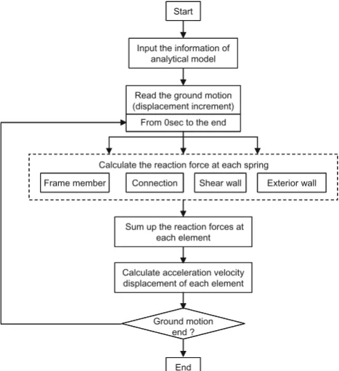
Figure 1 shows the methodology of our numerical simu-lation. First, the earthquake ground motion is input to the bottom of the analytical model. Second, the reaction forces of each spring are calculated by solving the equilibrium force equations. Finally, the reaction forces are summed up for each element, and the acceleration, velocity, and dis-placement of each element of the analysis models are cal-culated at the same time in each step.
Modeling of frame members
The skeleton structure of the analysis model consists of frame members. The parameters of the frame members were defi ned by the characteristic values of wood used in the analysis target. In the following analytical model, the modulus of elasticity of the frame members was uniformly defi ned as 6.5 kN/mm2
, and the bending strength was defi ned as 40 N/mm2
. The maximum bending moment was defi ned by the modulus of section of each frame member, respectively.
Modeling of connections between frame members
As shown in Fig. 2, the frame members (columns, beams, sills, and braces) of the analysis model consist of beam ele-ments connected in a series. The joints between frames
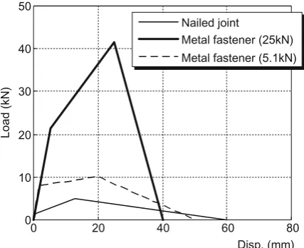
were modeled by two kinds of springs. One is the spring that acts against the tensile and compressive forces, and the other is the spring that acts against rotational movement. The load–displacement relationships of these nonlinear springs were determined by other work7
(Fig. 3).
Modeling of exterior walls
Exterior walls such as the mortar wall were not defi nitively estimated as a seismic element of the wooden houses by the Japanese building code, but the contribution of the mortar
Read the ground motion (displacement increment)
From 0sec to the end
Frame member Connection Shear wall Exterior wall Calculate the reaction force at each spring
Start
Input the information of analytical model
Sum up the reaction forces at the each element
Calculate acceleration velocity displacement of each element
Ground motion end ?
End Start
Input the information of analytical model
Sum up the reaction forces at each element
Calculate acceleration velocity displacement of each element
End
Fig. 1. Flow of the numerical analysis by the extended distinct element method
Sill Column
Beam element Beam
element
Tension Complession
Rotation Spring Element for fastener 227.5mm
227.5mm
wall to the seismic performance is not negligible,8
if the wall is adequately made. A conventional Japanese mortar wall consists of columns, beam, metal lath, and the mortar plas-tered over them. In this method, we modeled the mortar wall as shown in Fig. 4. The exterior mortar wall was modeled by frame elements and mortar elements. The frame elements correspond to wood lath (the sawn lumbers
used for backing of mortar plastering), defi ned as the wood lath element here. The wood lath elements consist of beam elements connected in a series, and were connected to column elements by nail springs. The mortar elements consist of triangular solid elements and were connected to wood lath elements by staple nail springs. Figure 5 shows the stress–strain relationship of the mortar element. The mortar elements were set to disappear when the tensile stress in the triangular solid elements exceeded fracture conditions to represent the crack developing process. By detailed modeling of the exterior mortar wall, the crack expanding behavior and the size effect on the shear capacity of the mortar walls were taken into account automatically during calculation.
The staple nail springs between wood lath and frame elements were nonlinear shear springs. Their load–displace-ment relationships were determined by the shear tests of the walls corresponding to this target specimen.9
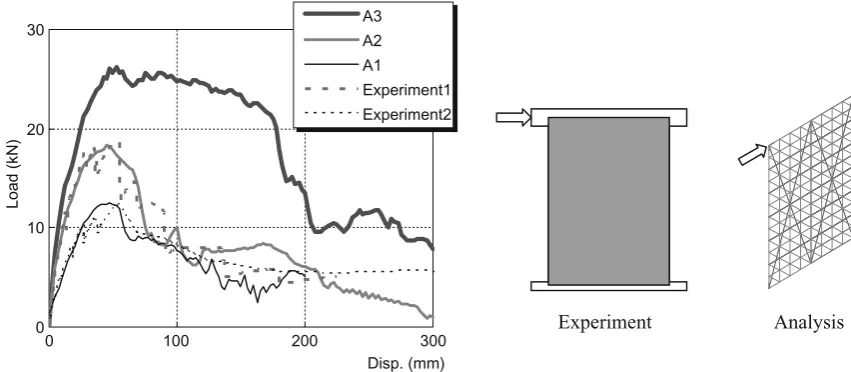
Figure 6 shows the load–displacement curves of the shear tests com-pared with numerical simulation under the same conditions. Because the strength of the staple nails greatly affects the seismic performance of the overall exterior mortar wall, the shear strength of the wall in the analysis model was adjusted to the results of the shear tests by changing the parameters of the staple nail elements. Three different load– displacement relationships (A1–A3) were used in the numerical modeling of the exterior wall. The representative characteristic values of shear walls in each analytical model are listed in Table 1.
0 10 20 30 40 50
0 20 40 60 80 Disp. (mm)
Load (kN)
Nailed joint
Metal fastener (25kN) Metal fastener (5.1kN)
Fig. 3. Load–displacement relationships of joint springs used in the analytical model. The value of the metal fasteners means the short-term allowable tensile load regulated by Ministry of Construction notifi ca-tion no. 1460 in 2000
Fig. 4. Confi guration of mortar wall elements of the analytical models
-10 -8 -6 -4 -2 0 2
-400 -300 -200 -100 0 100
Strain (10-6)
Stress (N/mm
2 )
Mortar
Fig. 5. Stress–strain relationships of mortar elements of the analytical models
Table 1. Characteristic values of representative aseismic elements
Aseismic element Initial stiffness (kN/mm)
Maximum resistance (kN)
Displacement at maximum resistance load (mm)
Exterior mortar wall (A1) 0.50 12.6 52.5 Exterior mortar wall (A2) 1.00 18.4 45.0 Exterior mortar wall (A3) 1.30 26.3 47.5
Mud walla 0.27 10.6 53.0
Modeling of mud walls and fl oors
Figure 7 shows the confi guration and the load–displacement relationships of the mud wall. The mud walls were replaced by the two diagonal springs (brace substitution) and were modeled as truss elements. The load–displacement relation-ship of the truss elements of the mud walls acting as the seismic elements were defi ned empirically by comparison
between the shear wall experiments9
and the calculation of the equivalent analytical models. Figure 7c shows the restor-ing force characteristic of the truss elements. The restorrestor-ing force characteristic model was defi ned by the bilinear and slip curves.
The fl oors were also modeled by the truss elements, and the truss elements of the fl oor were assumed to be rigid.
Experiment Analysis 0
10 20 30
0 100 200 300
Disp. (mm)
Load (kN)
A3 A2 A1
Experiment1 Experiment2
Fig. 6. Load–displacement relationships of the mortar wall elements of the three analytical models. A1, A2, A3, exterior mortar walls defi ned in Table 2
Brace substitution
(a) Configuration of mud wall element 0 2 4 6 8 10 12
0 100 200 300 400
Disp. (mm)
Load (kN)
Mud wall
(b) load-displacement relationship
P
Disp.
P2
D1D2 D3
P3
Disp.
P
D2 D3
Ks1
Ks2
Ks3
P
Disp.
D1
Kb1 Kb2
(c) Restoring force characteristic
Numerical analysis
Analysis model
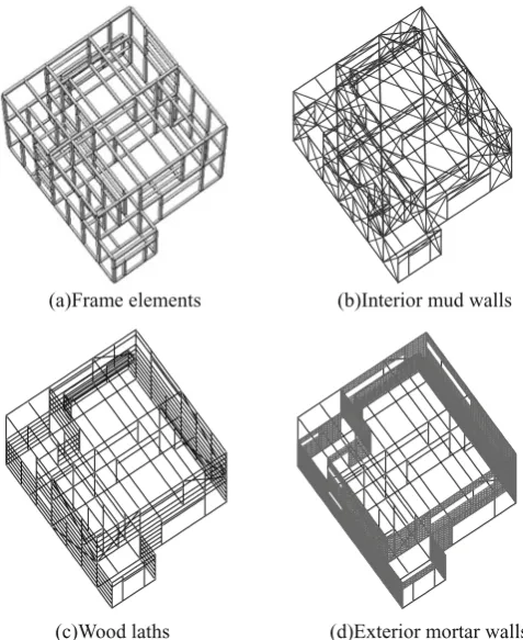
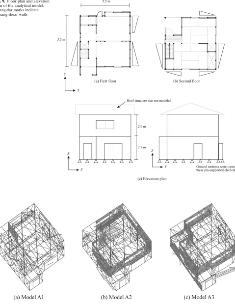
The analysis models used here are depicted in Fig. 8. The size of the analysis model is 5.5 m × 5.5 m. This model is a two-story, real-size wooden house. It has three living rooms and one dining and kitchen room. The total number of nodes for analysis models is 4 604, and the number of degrees of freedom is 27 624. The plan of this analysis model was based on the specimen used in the shaking table test. Figure 9 shows the fl oor plan and the elevation plan of the tested specimen and analytical model. This specimen is a conventional post-and-beam wooden two-story Japanese house that was built in 1974 in a Japanese city and trans-ported to be used as the shaking table test specimen. The shaking table test for this house was conducted at E-Defence (a full-scale shaking table in Miki City, Hyogo Prefecture, Japan) under the project “A Special Research Project for Earthquake Disaster Mitigation in Urban Areas” in Decem-ber 2005.10
The grade defi ned by the guideline for seismic diagnosis and retrofi tting in Japan11 is 0.5. This value means the rate to the demand level at the Japanese building stan-dard, so the risk of collapse is identifi ed as “high” according to the guidelines.
The parameters of the connections were defi ned accord-ing to the specifi cations of the target specimen, and the corresponding load–displacement relationships in Fig. 3 were selected for each connection, respectively. The cross
section of frame elements and the joint specifi cation of the analytical model are shown in Table 2. The mass of the analysis model was equalized with the actual weight of the target specimen measured by the load cell of the crane before the shaking table test. The weight of the fi rst fl oor was 119.1 kN, and the weight of the second fl oor was 91.4 kN. The weight was distributed to the element of each fl oor in the analysis model.
All lateral elements against the horizontal forces in the shaking table specimen were modeled in the analytical model. The roof structure was not modeled but was accounted for as seismic weight. The damping coeffi cients were defi ned to be 5.0%. The method of determination for damping coeffi cients of large deformation analysis such as our model requires ample studies, but we temporarily defi ned it by the experimental results at the vibration test12 of the target specimen. We used the instantaneous stiffness proportional damping. The damping coeffi cients were assumed to be zero, when the instantaneous stiffness became negative as a matter of analytical convenience.
Ground motion
Two earthquake waves were used as the input ground motion in the numerical simulations. One is the wave recorded at East Japan Railway Company’s Takatori station in the 1995 Kobe Earthquake and is called “JR Takatori.” The seismic intensity of JR Takatori is a 7 on the Japanese scale. The other wave is an artifi cial earthquake wave,13 called “BCJ level 2.” The latter wave is used for structural design in terms of the Japanese building code. JR Takatori was input to the frames at the bottom of the fi rst fl oor by changing the X–Y–Z displacement thereof. BCJ level 2 was input on the x-axis of the numerical element. The earth-quake ground motion was applied as the disturbance input of the displacement.
Simulation results
Figure 10 shows the appearance of the analysis model after BCJ level 2 input. The thick mesh line shows the surviving mortar elements of three different performance mortal walls. The three analytical models did not collapse, but many cracks occurred in the mortar, and almost all
(b)Interior mud walls
(c)Wood laths (d)Exterior mortar walls
(a)Frame elements
Fig. 8. Confi guration of the analytical models
Table 2. Basic information of analytical model
Cross section
Column 100 × 100 mm
Sill 85 × 85 mm
Beam 150 × 150 mm
Joints
Column-sill Nailed joint (N75 type nail) Beam-beam Metal fastener (5.1kN)
Staple nail 1210F type nail
r o o l f d n o c e S ) b ( r
o o l f t s r i F ) a (
5.5 m
X Y
X Z
5.5 m
Y Z
2.6 m
2.7 m
(c) Elevation plan
Roof structure was not modeled
Ground motions were input to these pin-supported elements.
Fig. 9. Floor plan and elevation plan of the analytical model. Triangular marks indicate bracing shear walls
(a) Model A1
(b) Model A2
(c) Model A3
the mortar elements fell down in model A1. The shear deformation of the most internal mud wall exceeded 1/50 rad. The restoring force of the model greatly decreased compared to the virgin condition, so this result suggests the occurrence of more heavy damage by the next aftershock. Because the seismic capacity of this model is about the half the level demanded by the Japanese building code, the simulation damage results are appropriate.
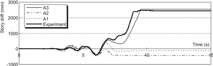
The shaking table specimen and all the analysis models collapsed in the JR Takatori input. Figure 11 shows a time series of the fi rst-story drift, defi ned as movement of the second-fl oor gravity center, of the analytical model houses with three different performance mortar walls (A1, A2, and A3) and the experimental result of a real house by JR Takatori input. The direction of the fracture differs among analysis models. The collapsing process of the analytical results of model A3 corresponds well to the experimental result. The collapsing process of model A1 and model A2 is similar to the experimental results in the small deforma-tion region (story drift, <500 mm), but the directions of collapse differed.
Figure 12 shows the load–displacement relationships of the experiment and analysis (A3). The maximum story shear of the experiment was larger than that of the analysis.
-1000 0 1000 2000 3000
15 10
5 0
Time (s)
Story drift (mm)
A3 A2 A1 Experiment
Fig. 11. First-story drift of the three analytical models and experimental results. A1, A2, and A3 indicate the model houses equipped with the mortar walls indexed in Table 2
-150 -100 -50 0 50 100 150
-0.6 -0.4 -0.2 0 0.2 0.4 0.6
Storey drift (m)
Storey shear (kN)
Analysis A3
Experiment
Fig. 12. Relationship between storey shear and fi rst-story drift of ana-lytical models and experiment
The total shape of the load–displacement relationship of the analysis was similar to the experimental result in the collapsing process.
By these numerical results, the load–displacement rela-tionships between the mortar walls were considered to be similar to those of model A3. It is important to estimate the restoring force of the exterior mortar wall, which is neglected in the building code as shear wall, to predict the detailed fracturing pattern via the difference of the fracture pattern among the analytical models.
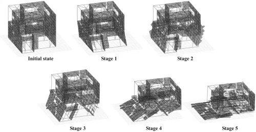
Figure 13 shows the results of the numerical simulation of model A3. The cracks occurred at the mortar wall at stage 1, and the mortar walls of the fi rst story started to fall down at stage 2. At stage 3, story drift exceeded 1/3 rad, and the descent of the second-fl oor level became larger by the P-Δ effect. Finally, the fi rst story collapsed, and the second story fell down at steps 4–5. Figure 14 shows a video still of the shaking table test. Similar fracturing patterns were observed in the shaking table test.
We also investigated the detailed fracture process of mortar wall in the JR Takatori input. Figure 15 shows an example of the stress distribution of the analysis model. Crack-developing behavior is observed around the window openings in this model.
Conclusion
Collapsing process simulations for real-size wooden houses were carried out using our newly developed calculation program based on the extended distinct element method. The collapsing process results from one of the analyses cor-respond well to the experimental results. We determined that the collapsing process simulation, including the fractur-ing behavior of the exterior wall, was possible by our analy-sis method.
Stage 1 Stage2 e
t a t s l a i t i n I
5 e g a t S 4
e g a t S Stage 3
Fig. 13. Simulation results of analytical model A3 during JR Takatori excitation. Thick lines show mortar walls.
Fig. 14. Collapsing process of specimen in the shaking table test (JR Takatori)
References
1. Japan Housing and Wood Technology Center (2007) Design guideline of limit seismic resistance calculation for wooden post and beam construction houses (in Japanese). Japan Housing and Wood Technology Center, Tokyo
2. Tsuchimoto T, Sugimoto K, Aoki K, Isoda H, Nakagawa T, Fuku-moto Y (2008) Study on shear strength and limit deformation to collapse of old wood houses (in Japanese). In: Summaries of Tech-nical Papers of Annual Meeting of the Architectural Institute of Japan C-1:103–104
3. Yoshioka K, Tuda C, Akiyama T, Miyazawa K (2007) Statically destructive loading test of existing wooden house. Part 6. 52 years old one-storey house in Sizuoka: results of loading test (in Japa-nese). In: Summaries of Technical Papers of Annual Meeting Architectural Institute of Japan C-1:467–468
4. Miyake T, Minowa C, Isoda H, Koshihara M, Tsuchimoto T, Saka-moto I (2008) Collapsing response analyses of existing wood houses corresponding to shaking table test. In: Proceedings, World Conference on Timber Engineering, 2008, p 286
5. Nakagawa T, Ohta M (2003) Collapsing process simulations of timber structures under dynamic loading. I: Simulations of two-story frame models. J Wood Sci 49:392–397
6. Nakagawa T, Ohta M (2003) Collapsing process simulations of timber structures under dynamic loading. II: Simplifi cation and qualifi cation of the calculating method. J Wood Sci 49:499–504 7. Japan Housing and Wood Technology Center (1996) Report of
works on development of technology for joint design of timber
post and beam construction houses: WG of test on column bottom joints (in Japanese). Japan Housing and Wood Technology Center, Tokyo
8. Miyamura M, Ohta M, Sato M (2006) Shear strength and fracture mechanism of lath-mortar wall. I. Analysis of shearing deformation of mortar wall with lath board (in Japanese). Mokuzai Gakkaishi 52:303–311
9. Nakagawa N, Kawai N, Tsuchimoto T, Okabe M (2006) Verifi cation for seismic performance of existing wood houses by shaking table tests. Part 15: Structural performance of wooden frame walls in the building by shaking table tests (in Japanese). In: Summaries of Technical Papers of Annual Meeting of the Architectural Institute of Japan C-1:395–396
10. Nakamura I, Shimizu H, Minowa C, Sakamoto I, Suzuki Y (2006) Full scale shaking table tests for post and beam wooden houses by E-Defence. In: Proceedings of First European Conference on Earthquake Engineering and Seismology, no.733
11. The Japan Building Disaster Prevention Association (2004) Seismic performance evaluation and strengthening method for timber houses (in Japanese). Japan Building Disaster Prevention Association, Tokyo
12. National Research Institute for Earth Science and Disaster Pre-vention (2006) A special project for earthquake disaster mitigation in urban areas. II: Working papers (in Japanese). National Research Institute for Earth Science and Disaster Prevention, pp 99–116