http://www.sciencepublishinggroup.com/j/ajpa doi: 10.11648/j.ajpa.20190706.11
ISSN: 2330-4286 (Print); ISSN: 2330-4308 (Online)
Study on the Single-Lens Telescope and Its Imaging
Parameters
Kaixin Pan
1, Yiran Liu
2, Zhimin Pan
31
Department of Biomedical Engineering, Case Western Reserve University, Cleveland, United States 2Department of Physics, Nanjing Foreign Language School, Nanjng, China
3
Department of Physics, Peking University, Peking, China
Email address:
To cite this article:
Kaixin Pan, Yiran Liu, Zhimin Pan. Study on the Single-Lens Telescope and Its Imaging Parameters. American Journal of Physics and Applications. Vol. 7, No. 6, 2019, pp. 136-143. doi: 10.11648/j.ajpa.20190706.11
Received: April 5, 2019; Accepted: June 24, 2019; Published: November 7, 2019
Abstract:
From Galileo telescope designed in 1609 to the recent advanced astronomical telescope, telescopes always help people in coping with different problem. The relation between the parameters of telescope and its performance has been a hot topic for a long time. In this paper, we have designed a simple single-lens telescope based on the Problem No. 3 in International Young Physicist Tournament (IYPT2017) and have done the research related to the performance of our telescope. Here, we mainly focus on the magnification, the contrast and the brightness To demonstrate the performance of our single-lens telescope, According to the theories of geometric optics and physical optics, we have systematically explored the influences of aperture and focal length on the magnification of the telescope, the contrast and brightness of the images and so on, we have experimentally conducted quantitative studies by varying these parameters and elaborate analysis of data with software including MATLAB and Toup View. According to the data and numerical simulation we get in our experiment, we found that our experimental results are consistent with our theory so that a generic conclusion has been drawn. Besides, possible origination of errors in the studies has been discussed and an outlook has been proposed.Keywords:
Pinhole Imaging, Single Lens Telescope, Magnification, Contrast, Sharpness, Brightness1. Introduction
Since the first telescope was developed by Netherlander Hans Lippershey in 1608, telescopes have been applied in ordinary observation and academic research. Hubble telescope, launched in 1990, provided us the opportunity to detect our universe. An ordinary telescope mainly consists of at least two lenses. In this paper we propose a simple optical model to design a single-lens telescope by replacing the ocular lens with the pin-hole imaging, and the performance of the new designed is systemically investigated.
2. Theoretical Study on Single-lens
Telescope
2.1. Kepler Telescope vs Single-lens Telescope
Kepler telescope represents the most frequently and
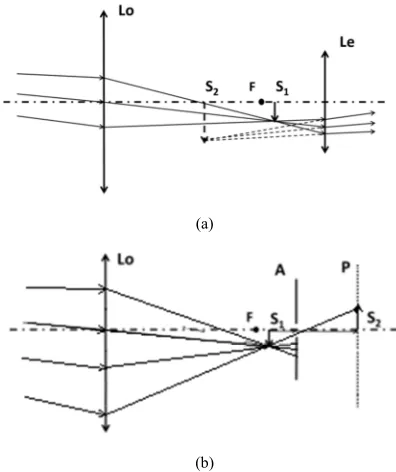
extensively used telescope. As shown in Figure 1 (a), it is composed of two pieces of convex lenses. A distant object forms an upside-down intermediate real image S1 behind the
objective lens Lo in a near point. Then the eyepiece Le acts as a
magnified inverted image. S2 is presented after its refraction of
intermediate image.
Contrarily, in the single-lens telescope, a pin-hole A is adopted to replace the eyepiece to magnify the intermediary image following the principle of pin-hole imaging, as shown in Figure 1 (b). In fact, no "image" arises in the pin-hole imaging process and only "magnification" function is realized according to the geometrical rules. In addition, the pin-hole's size defines the diameter of the light beam emitted from one point of the object plane, thus affecting the sharpness of imaging.
theories and experiments related to these parameters.
(a)
(b)
Figure 1. (a) Observe non-infinite objects by Kepler telescope. (b) Basic optical path of the single-lens telescope.
2.2. Apparent Angular Magnification
In general, there is a long distance from the observing object to the telescope. It can be assumed that the object is at an infinite distance and the intermediate image is presented on the focal plane of the objective lens. Observing an object at a remote distance, we use apparent angular magnification to represent the magnifying function of the telescope. The apparent angular magnification M is defined as the ratio between the field angle ω' of the image formed in the end against human eye (pupil) and that of the object at the actual position against human eye.
M= ω'/ ω (1)
Figure 2. Schematic show of the denotation in the optical path of the single-lens telescope. As shown in Figure 2, we assume that in this optical system the light beams are parallel and that the distance u from the object to the objective lens is much greater than the focal length f, move eyes closer to the screen for observation. The apparent angular magnification of the single-lens telescope can be deduced as:
, (2)
Where s and t refers to the "object distance" and "image distance" of pin-hole imaging and s0 represents the distance
from the optical screen P to the observer.
It can be seen that the apparent angular magnification of the
single-lens telescope and the position of the pin-hole is closely correlated to each other, and they are positively correlated with the objective lens' focal length.
2.3. Resolution Ratio
2.3.1. Theory of Geometrical Optics
The finite size of the pin-hole will cause the point on the object plane blurred while imaging. Based on our research of pinhole imaging5
, when the distance between two faculae on the image plane equal to their radius, it can be regarded as distinguishable. If two points at a distance of δ on the object plane are distinguished, δ can be deduced through geometrical optics (the process omitted):
δ , (3)
where d represents the pin-hole diameter, and the denotation of the other parameters are shown in Figure 2.
It can be obtained that the minimum distance δ distinguished by the single-lens telescope is directly proportional to the pin-hole diameter d and negatively correlated with the distance t between the pin-hole and the screen.
2.3.2. Diffraction Theory
When the pin-hole has a small size, the impact arising from light diffraction should be taken into consideration. Given the pin-hole diameter is d and lens diameter is D.
First, we consider the influence of objective lens (lens). Given ≫ , the incidence light can be approximated as parallel light. According to the relevant conclusions of Fraunhofer diffraction, the minimum resolution range is:
δ 1.22 ∙ 1.22 . (4)
Taking the experiment parameter that D=50mm and 5m it shows that, δ 0.1mmwhen wave length λ=550nm. Therefore, the influence of lens diffraction on resolution can be neglected.
Next, we will consider the influence of pin-hole diffraction. In our experiment, in order to ensure the telescope's magnifying power, s, t >> d in most cases. As a result, the actual diffraction effect has a little difference with Fraunhofer diffraction of parallel light. Hence, the approximate theoretical result of Airy disk can be used, i.e. ∆ 1.22 . The minimal resolution range arising from pin-hole diffraction is
δ 1.22 (5)
and the specific function relationship can be derived from Fresnel diffraction of pin-hole.
Figure 3. Schematic show of the resolution as a function of the pin-hole diameter.
Figure 4. Schematic shows derivation of Fresnel diffraction.
As shown in Figure 4, the complex amplitude of the spherical wave emitted from "point" on plane A where the pin-hole locates can be presented as
!
" # "$%&e() &
, (6)
Where u0 and r0 are constants;* +, s- AQ √1 2 #
and r represents the distance from a certain point in the pin-hole to the pin-hole center. According to Kirchhoff's diffraction formula, the complex amplitude of point P at the distance of ρ to the optic axis on the screen is
3
" 4 "5 #$6 6$+ $8 7 cos $2 cos ;<=>?5)@
& &AB
C& & # D#DE, (7)
where F- AP H4 2 # I 24# cos E 2 F , , $
represent the angle formed bylines AQ, AP and the pin-hole plane. Refer to Figure 4 for other parameters.
Under the paraxial approximation neglecting the small change in the inclination factor 7 cos $2 cos and
J3 4 " 4 ∙3 L 43∗ (8)
Given it is hard to present the analytical expression of this amplitude, it can be obtained
3
" 4 MLNOP QR*$ S
T
U 6 NOP QR* V$8 %T2%TWU⋅ 2YZ$V)S#W ⋅ #D#. (9)
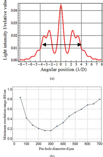
The light intensity of point P is integration, we adopt computer numerical simulation to draw the functional graph of light intensity distribution, as shown in Figure 5 (a). This figure presents the simulation result of a group of typical experiment data including S=50mm, t=250mm and d=500µm. Wherein, the wave length is taken as 550nm and the lens focal length as 200mm.
Conventionally, the distance on the corresponding object plane to the full width at half maximum of the peak is taken as the minimal resolution range. However, as for Fresnel diffraction, the beam spot center is dark space or has complicated light intensity fluctuation in some cases, thus leading to certain difficulties for defining "just discerned". For instance, as shown in Figure 5 (a), the position at half of the height of the external side is taken as the reference to calculate the minimal resolution range. Therefore, if s=50mm, t=250mm remains unchanged, the curve of the minimum resolution rangeδ as the pin-hole diameter d changes is as shown in Figure 5 (b). It is worthy to mention that such criteria may lead to certain deviation.
It can be found that the overall trend of the graphic line (approximately) verifies the above theoretical deduction. The curve reaches a minimal value at a specific position, which corresponds to the pin-hole diameter when the highest resolution occurs.
(a)
(b)
2.4. Contrast Ratio
While observing the nonopaque fence-like resolution panel with intervals (as shown in Figure 6), the shade difference between the black and white imaging areas is called contrast ratio or contrast. In the actual test, we adopt the following formula to represent the contrast ratio of graphics:
Figure 6. Schematic show of the object.
φ \]5^_ `\ a%)\]5^_ \ a%) (10)
where repre sents the light intensity value in the light permeable area of the resolution panel, while represents that in the lighttight area. In the ideal condition, the contrast ratio is 1. If the light and dark stripes are completely indistinguishable, the contrast ratio is 0. Generally speaking, a graph cannot be clearly distinguished by human eyes when its contrast ratio reaches 0.4.
Both the contrast ratio and resolution reflect the image sharpness of the single-lens telescope.
2.5. Brightness
The brightness usually refers to the brightness of light source, while brightness herein taken into account refers to light intensity of the image plane, i.e. the Illuminance. It is defined as the energy of visible light absorbed by a unit area and refer to describing the light intensity and sharpness of the object surface illuminated. When the luminous flux on the surface element dS is given as dФ, the illuminance E on this surface element is
E=dΦ/dS (11) It is obvious that the larger the pin-hole is, the greater light will run through. That is, the illuminance on the imaging plane positively correlates with the pin-hole size.
3. Experimental Study on the Single-lens
Telescope
3.1. Experimental Apparatus and Parameters
(1)Convex lenses with diameter of 25mm and focal length
of 100mm, 125mm, 150mm, 175mm and 200mm respectively. (2) Convex lenses with diameter of 50mm and focal length of 200mm.
(3) Fixed pin-holes with diameters of 50µm, 100µm, 200µm and 500µm.
(4) Variable pin-hole with diameters greater than 800µm. (5) CMOS photographic system (including CMOS camera and 0.6 telecentric lens).
(6) Objects under observation: incandescent lamp, black adhesive tape (cuttable), resolution panel (self-manufactured).
(7) Frosted glass (used as the optical screen).
(8) Other parts: optical table, element holder, experimental gloves and so on.
3.2. Experimental Procedures and Contents
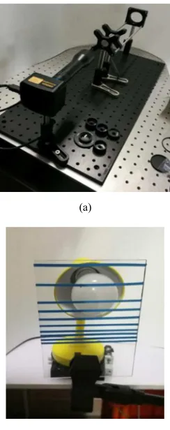
As shown in Figure 7 (a), the CMOS photographic system, the frosted glass screen, the pinhole and the lens are assembled in accordance with the theoretical optical path. Each element is adjusted to be coaxial and of equal altitude and in alignment with the resolution panel used as object (as shown in Figure 7 (b)). The distance between the pin-hole and the photographic system is carefully adjusted to enable the pictures on frosted glass screen observed clearly through the CMOS photographic system. The pictures are displayed on the computer screen as shown in Figure 7 (c). We change the position (related to the pin-hole) of the screen t, the pin-hole diameter d, the lens diameter D, the focal length f and other parameters successively, and make further analysis of each parameter of the picture by computer software, such as MATLAB and ToupView.
(a)
(b)
Light
I
(c)
Figure 7. The setup of the CMOS photographic system used in the experiment (a), the object (b) and the image (c).
For the telecentric lens in use, the ratio between the pixel distance and the actual distance is a certain constant value. We can measure the distance between any two random points on the picture through software and calculate the actual distance between stripes in the picture (the size of image being H2) by
the lens' magnification times and the pixel size of the CMOS camera chip. Then it can be compared with the resolution panel to calculate the actual magnifying power M of the telescope.
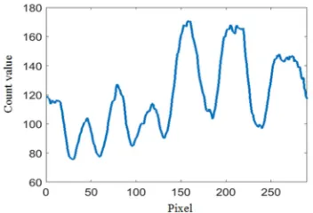
We then Input the picture into MATLAB, extract light intensity values of a column of pixels in the center of the picture and exhibit its light and shade trend as shown in Figure 8. Then we read the difference value between adjacent peak and valley in the Figure, divide it by the average value of the peak and valley data, and calculate the contrast ratio in accordance with the Formula (10).
Figure 8. Digitalization of the image mediated by MATLAB.
In each experiment, we select a small portion of the picture and maintain its gray level at a constant value by using exposure time and gain of the ToupView automatic adjusting camera. From this we can measure the relative brightness by using the reciprocal value of the product of exposure time and the gain.
3.3. Research and Analysis of Experimental Data
In the experiment, we fix the distance between the lens and the screen at 300mm and the distance between the object (the resolution panel) and telescope at about 4.8m.
3.3.1. Relations Between the Magnifying Power M and the Distance Between the Pin-hole, and the Screen t and Lens Focal Length f
In the experiment of studying the relation between
magnifying power M and the distance between the pin-hole and the screen t, we select the lens with 50mm diameter and 200mm focal length and the pin-hole with 100µm diameter. Based on the experimental data, the relation between magnifying power M and the distance between the pin-hole and the screen t is concluded as shown in Figure 9 (a).
In the experiment of studying the relation between magnifying power M and lens focal length f, we select respectively the lens with diameters of 100mm, 125mm, 150mm, 175mm and 200mm, and the pin-hole with 100µm diameter, and set the distance between the pin-hole and the screen as 67mm. Based on the experimental data, the relation between magnifying power M and the distance between the pin-hole and the screen t is concluded as shown in Figure 9 (b).
It is found through the experiment that the apparent angular magnification of the single-lens telescope correlates positively with the distance between the pin-hole and the screen and correlates negatively with the lens focal length. This is in conformity with the former theoretical expectations.
(a)
(b)
Figure 9. (a) Relation between magnifying power M and the distance between the pin-hole and the screen t. (b) Relation between magnifying power M and lens focal length f.
3.3.2. Relations Between the Sharpness and the Distance Between the Pin-hole and the Screen t and the Pin-hole Diameter d
ratio E and the distance between the pin-hole and the screen t, we apply the lens with 50mm diameter and 200mm focal length and the pin-hole with 100µm diameter. After measuring the light intensity values in both the light permeable area and the light proof area of the resolution panel and putting them into the formula (10) to calculate the contrast ratio E, the relation between the contrast ratio Eand the distance between the pin-hole and the screen is concluded as shown in Figure 10 (a).
In the experiment studying the relations between the contrast ratio E and the pin-hole diameter d, we apply the lens with 50mm diameter and 200mm focal length, set the distance between the pin-hole and the screen at 67mm, and select respectively the pin-holes with diameters of 50µm, 100µm, 200µm and 500µm. Based on the experimental data, the relation between contrast ratio E and pin-hole diameter d is concluded as shown in Figure 10 (b).
(a)
(b)
Figure 10. (a) Relation between the contrast ratio and the distance between the pin-hole and the screen t; (b) Relation between contrast ratio and the pin-hole diameter d.
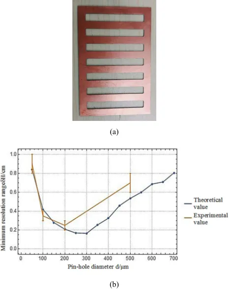
In the experiment studying the changing of the minimum resolution range δH with the pin-hole diameter, we apply the self-manufactured fence-like aluminum plate with different intervals as the simple resolution panel (as shown in Figure 11
(a)) and measure generally the resolving power of the single-lens telescope. The contrast between the experimental results and theoretical values is shown in Figure 11 (b). Due to the restrictions of manufacturing capabilities, we only apply the resolution panel with integer millimeter interval and cannot acquire more accurate values for the minimum resolution range δH. In the figure, the top end of the vertical line for each experimental value represents the discernable interval of the thinnest panel while the bottom end represents the indiscernible interval of the thickest panel, and the actual value falls between the two ends. The figure shows that the changing trends of the experimental and theoretical values take on a good consistency. When the pin-hole is too large, the actual resolving power of the telescope is lower than predicted. This may derive from the inaccuracy of the criteria for judging the "Just discerned" in theories.
Contrast ratio and resolution ratio (the minimum resolution range) both reflect the image sharpness of the single-lens telescope. It is found through experiment that: the image sharpness of the single-lens telescope correlates positively with the distance between the pin-hole and the screen; when the pin-hole diameter is too large or too small, the image from the single-lens telescope is not clear. This conclusion is important to guide significance in improving the performance of telescopes, such as the choice of the pin-hole.
(a)
(b)
Figure 11. (a) Self-manufactured resolution panel; (b) Relation between the minimum resolution range δH and the pin-hole diameter d.
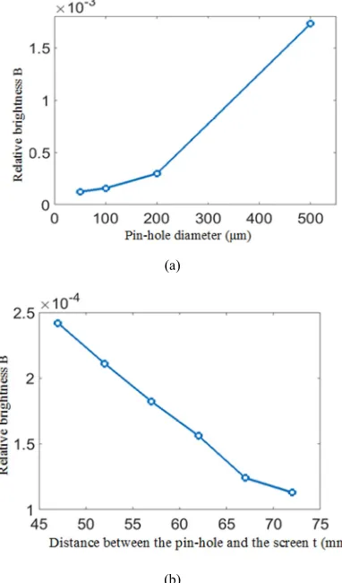
3.3.3. Relation Between the Brightness and Pin-hole Diameter d, and the Distance Between the Pin-hole and the Screen t
brightness and the pin-hole diameter d, we apply the lens with 50mm diameter and 200mm focal length, set the distance between the pin-hole and the screen at 67mm and the gray value at 200, select respectively the pin-holes with diameters of 50µm, 100µm, 200µm and 500µm, and conclude the relations between relative brightness B and the pin-hole diameter as shown in Figure 12 (a).
In the experiment studying the relation between the brightness and the distance between the pin-hole and the screen, we apply the lens with 50mm diameter and 200mm focal length, select the 100µm pin-hole, set the gray value at 150 and conclude the relation between the relative brightness B and the distance between the pin-hole and the screen t as shown in Figure 12 (b).
(a)
(b)
Figure 12. (a) Relation between relative brightness B and pin-hole diameter d; (b) Relation between relative brightness B and the distance between the pin-hole and the screen t
It is found through experiments that the image brightness of the single-lens telescope correlates negatively with the distance between the pin-hole and the screen, and correlates positively with the pin-hole diameter. This is in conformity with the theoretical expectation.
4. Error Analysis
4.1. Errors in the Theoretical Study
In the theory, the paraxial approximation of light can lead to
errors. Also, when we use simulation program to determine the minimum resolution range, errors can emerge due to both the inaccuracy of the calculation and that of judging just discerned.
4.2. Errors in the Experimental Study
The errors may derive from the adjustment of the optical path in the experiment and the measurements of each length (such as the distance between the pin-hole and the screen). Even though experiments are conducted in a dark environment, there are still errors deriving from the noisy signals from walls or stray light. In image analysis, due to the limited image sharpness, errors can emerge in the selection and measurement of pixel point. Even though the high-quality adhesive achromatic lens is applied in the experiment, the chromatic aberration and optical aberration of the lens are still in existence.
5. Conclusion and Outlooks
5.1. Conclusions
In this paper we present a solution to replace eyepiece with pin-hole imaging, and thus build a simple optical model to design the single-lens telescope. We discover the relations between imaging parameters of single-lens telescope, like magnification, sharpness and brightness, and its lens parameters, like pin-hole size and focal length through theoretical analysis and experimental research. The theory and the experiment in this paper have good self-consistency.
In terms of theoretical research, the apparent angular magnification formula is worked out from the apparent angular magnification definition, namely, M cc&
Resolution formula is worked out from the Gaussian imaging formula and the geometrical relationship: δ
. Considering the similarity with geometrical optics, the effects of diffraction should be put into account when the pin-hole size is quite small. By wave optics exploration, it is found that this can be viewed approximately as Fraunhofer diffraction, namely, Δθ 1.22 . The minimal resolution range arising from pin-hole diffraction is δ
1.22 . Further strict theoretical analysis and computer software simulation show that the resolving power of this telescope has a complex functional relationship with the pin-hole diameter. When the pin-hole diameter is set at an appropriate value, this telescope has a highest resolving power,
and the screen, and the telescope's image is not clear when the pore diameter is too large or too small. The image brightness of this telescope correlates negatively with the distance between the pin-hole and the screen, and correlates positively with the pin-hole diameter.
5.2. Outlooks
Multiple lens with different diameters and focal lengths, and pin-holes with different diameters can be applied in experimental research to break through the restrictions of experimental apparatus. More sophisticated measurement will be enacted elaborately through the professional resolution panel to lessen the restriction of the mechanical processing capacity. Numerous measurement experiments can be conducted to avoid unnecessary human operation errors and to increase the accuracy of experiments. Further theory and quantitative experimental research can be conducted to explore the relationships between sharpness, brightness and relevant parameters. Besides the magnification, resolution, brightness and contrast ratio, further researches should focus on the influences of more parameters on the telescope imaging capabilities.
6. Summary
In this paper, commencing from both the geometrical optics and the wave optics, we construct a single-lens telescope and quantitatively analyze each parameter's influence on the magnification, sharpness and brightness of the telescope. Through verification of experiments, we discover a self-consistency between the theory and the experiments. We hope that our research can offer some help and ideas for middle school students in their investigative studies and we
also expect for more criticism and corrections.
In the end thanks go to Metalab Innovative Laboratory for their providing of experimental apparatus and field, and to Doctor shangchi Jiang for his/her precious suggestions.
References
[1] Young M. Pinhole Optics [J]. Applied Optics, 1971, 10 (12): 2763-2767.
[2] Young M. The pinhole camera: Imaging without lenses or mirrors [J]. Physics Teacher, 1989, 27 (27): 648-655.
[3] Zhang Sanhui. University Physics. Thermotics, Optics and Quantum Physics [M]. Version 3 Beijing: Tsinghua University Press, 2009: 209-294.
[4] Zhong Xihua Modern Fundamentals of Optics [M]. Beijing: Beijing University Press, 2012: 61-76.
[5] Pan Zhimin, Jin Kaiwen, Pan Kaixin studies of the pinhole imaging [J]. physics and engineering, 2018, 28 (4).
[6] D. J. Lovell, "Optical Peregrinations in The Netherlands," Appl. Opt. 6, 785-791 (1967).
[7] Diffraction Theory of Electromagnetic Waves J. A. Stratton and L. J. Chu Phys. Rev. 56, 99 – Published 1 July 1939. [8] Reinhard W. Meier, "Magnification and Third-Order
Aberrations in Holography," J. Opt. Soc. Am. 55, 987-992 (1965).
[9] Wmo G E. Guide to meteorological instruments and methods of observation [J]. 1996.