Mech. Sci., 2, 17–26, 2011 www.mech-sci.net/2/17/2011/ doi:10.5194/ms-2-17-2011
©Author(s) 2011. CC Attribution 3.0 License.
Mechanical
Sciences
Open Access
A constrained optimization framework for compliant
underactuated grasping
M. Ciocarlie1and P. Allen2 1Willow Garage, Inc., Menlo Park, CA, USA
2Columbia University, New York, NY, USA
Received: 5 March 2010 – Revised: 16 June 2010 – Accepted: 19 August 2010 – Published: 8 February 2011
Abstract. This study focuses on the design and analysis of underactuated robotic hands that use tendons
and compliant joints to enable passive mechanical adaptation during grasping tasks. We use a quasistatic equilibrium formulation to predict the stability of a given grasp. This method is then used as the inner loop of an optimization algorithm that can find a set of actuation mechanism parameters that optimize the stability measure for an entire set of grasps. We discuss two possible approaches to design optimization using this framework, one using exhaustive search over the parameter space, and the other using a simplified gripper construction to cast the problem to a form that is directly solvable using well-established optimization methods. Computations are performed in 3-D, allow arbitrary geometry of the grasped objects and take into account frictional constraints.
This paper was presented at the IFToMM/ASME International Workshop on Underactuated Grasping (UG2010), 19 August 2010, Montr´eal, Canada.
1 Introduction
In this study, we present a framework for the analysis and optimization of a class of passively adaptive underactuated robotic hands. In a broad sense, this is the task of replacing elaborate run-time algorithms (often requiring extensive sen-sor arrays for input and complex actuation mechanisms for execution) with off-line analysis, performed before the hand is even built. We focus on highly underactuated hand mod-els, where the number of joints far exceeds the number of actuators, noting for example that recent studies have shown reliable grasping performance with even a single actuator for multiple fingers and up to 15 joints (Gosselin et al., 2008). In such cases, the only decision available at run-time is the placement of the hand relative to the target object, emphasiz-ing the importance of the design optimization step. As the fingers are closing, the only computation is performed at an implicit level, by the actuation mechanism itself.
Two important tools for achieving reliable performance when using passively adaptive hands are grasp analysis and
Correspondence to: M. Ciocarlie ([email protected])
design optimization. The former traditionally focuses on a single grasp, and attempts to compute a measure of its sta-bility under a given actuation mechanism. The latter aims to compute the parameters of the actuation mechanism itself, so that stability measures are maximized for a broad range of grasps. As the space of hand design parameters is extremely large, especially when taking into account kinematic consid-erations such as number of joints, number of fingers, finger link and palm shapes, we narrow the scope of this study as follows:
– we start from a given kinematic design, with a poten-tially large number of joints grouped into multiple fin-gers;
– assuming that each joint can be controlled indepen-dently, we create a set of stable grasps over a given group of objects. We refer to this set as the optimiza-tion pool;
18 M. Ciocarlie and P. Allen: A constrained optimization framework for compliant underactuated grasping There are multiple ways of achieving passive adaptation
with a robotic hand design. One of the earliest examples, the Soft Gripper introduced by Hirose and Umetani (1978), used tendons for both flexion and extension. Ulrich et al. (1988) pioneered the use of a breakaway transmission mech-anism which is now used in the Barrett hand (Barrett Tech-nologies, Cambridge, MA). Birglen et al. (2008) presented a detailed and encompassing optimization study for under-actuated hands, focusing mainly on four-bar linkages but with applications to other transmission mechanisms as well. Four-bar linkages were also used to construct the MARS hand (Gosselin et al., 1998), which later evolved into the SARAH family of hands (Laliberte et al., 2002). These stud-ies have led to the construction of remarkably efficient grip-pers and hands. In the process, they have highlighted the fact that optimization of a highly underactuated hand is a com-plex problem; in other words, simple is hard!
Our framework is based on the implementation of pas-sively adaptive underactuation using the mechanics of a tendon-actuated hand combined with compliant, spring-like joints. This is based on the work of Dollar and Howe (2006), who optimized the actuation and compliance forces of a sin-gle tendon design. This design was later implemented in the Harvard Hand (Dollar and Howe, 2007), which we also use here as one of our case studies. We found the relative ease of constructing a prototype using this actuation paradigm par-ticularly appealing, and believe it can lower the barriers for experimenting with new hand designs and disseminating re-search results. However, other actuation methods have their own merits, which must be considered in future iterations.
2 Problem formulation
The starting point for our optimization framework is the qua-sistatic equilibrium relationship that characterizes a stable grasp. We briefly review this formulation here; for more de-tails we refer the reader to the analysis by Prattichizzo and Trinkle (2008).
Consider a grasp with p contacts established between the hand and the target object. For any contact i, the total contact wrench cimust obey two constraints. First, the normal
com-ponent must be positive (contacts can only push, not pull). Second, friction constraints must be obeyed. A common method is to linearize these constraints, by expressing ci as
a linear combination of normal force and possible friction wrenches:
ci = Diβi (1)
βi, Fiβi ≥ 0 (2)
where the matrices Diand Fidepend only on the chosen
fric-tion model, such as linearized Coulomb fricfric-tion. The contact wrench is now completely determined by the vector of fric-tion and normal wrench amplitudesβi, which will be
com-puted as part of the grasp analysis algorithm.
In general, a grasp, as a collection of multiple contacts, is in quasistatic equilibrium if the following conditions are satisfied:
– contact forces are balanced by joint forces (hand equi-librium);
– resultant object wrench is null (object equilibrium); – contact constraints are met for all contacts in the grasp. We can assemble the complete grasp description as fol-lows:
JTcDβ = τ (3)
Gβ = 0 (4)
β, Fβ ≥ 0 (5)
whereτis the vector of joint forces, Jcis the Jacobian of the
contact locations and G is the grasp map matrix which relates individual contact wrenches to the resultant object wrench. The matrices D and F bring together the individual contact constraint matrices Diand Fifor i=1...p in block diagonal
form. The column vectorβcontains all contact amplitudes vectorsβiin block column form. In order to avoid the trivial
solution where all forces in the system are zero, a constraint can be added requiring total actuator forces to sum to a pre-specified level.
In our framework, we use the term “stable” to refer to grasps that are in quasistatic equilibrium (all of the above constraints are met). It is important to note that, in practice, this is not a sufficient condition for achieving form-closure using the given actuation mechanism. However, it is a nec-essary prerequisite and, as such, we believe that optimizing a hand to achieve equilibrium under many configurations is a valuable step towards enabling a wide range of grasps. A possible future extension would be to also include a direct measure of grasp quality, according to one of the metrics that have been proposed in the literature (Ferrari and Canny, 1992; Prattichizzo and Trinkle, 2008).
So far, this analysis applies to a hand design regardless of its actuation method. To adapt it to the case of underactuated hands, we must look in more detail at the joint force vector τ, which is a result of the actuation mechanism. We use the common tendon-pulley model, as used for example by Kwak et al. (2000), which assumes that a tendon travels through a number of routing points that it can slide through, but which force it to change direction as it follows the kinematic struc-ture. As a result of this change in direction, the routing points are the locations where the tendon applies force to the links of the finger. This model is illustrated in Fig. 1, with the rout-ing points marked with spheres. For clarity, the route shown is on the surface of the links, but in general the tendon can also be tunneled through the inside of the links.
M. Ciocarlie and P. Allen: A constrained optimization framework for compliant underactuated grasping 19
Figure 1.Illustration of tendon routing points (red spheres) as the tendon follows a revolute joint (wire frame cylinder).
We assume that the hand contains a total of d tendons, each with multiple routing points across different links. In this case, joint forces can be expressed as:
τ=JTdδ+θk (6)
where Jd is the Jacobian of the tendon routing points and
δ∈ Rdis the vector of applied tendon forces. θis a diagonal
matrix of joint angle values and k is the vector of joint spring stiffnesses (without loss of generality, we assume 0 is the rest position for all springs). We now have a complete description of the equilibrium state of the grasp, expressed in Eqs. (3) through (6).
In practice, one of the relationships comprised in this for-mulation is used as an optimization objective, rather than a hard constraint, with two important advantages. First, it provides more information for problems where all the con-straints are not feasible in their exact form. Second, prob-lems that have a solution in the exact form will often have an infinity of solutions; formulating an optimization objective allows us to choose an “optimal” one. Which of the above constraints is to be used as an optimization objective depends on the nature of the problem; as a result, this formulation is extremely versatile, and can be adapted to a number of prac-tical problems in underactuated grasp analysis:
– if the unknown variables include only the contact wrench magnitudesβ(and implicitly all the individual contact wrenches ci), we are computing whether a
par-ticular set of actuator forces results in a stable grasp;
– if we extend the set of unknowns to also include the vec-torδ, we are trying to compute the best actuator forces for a grasp characterized by a particular set of contacts;
– we can even extend the set of unknowns to include com-ponents of JTd or k, in which case we are computing the best hand design parameters for executing a given grasp (or set of grasps).
3 Grasp analysis
Using this framework, we can analyze the stability of a given grasp by using object equilibrium as an optimization objec-tive. We are interested in detecting finger slip on the object surface, as well as any unbalanced forces in the hand-object system; this analysis can be carried out both as the fingers are closing and after the grasp is complete. For a given hand posture and set of contacts, the goal is to determine the con-tact forcesβand actuation forcesδthat balance the system, or, if exact equilibrium is infeasible, result in the smallest magnitude wrench on the object:
minimize ||Gβ|| = βTGTGβ subject to : h
JTcD −JTdiβ δT = θk (7)
δ,β,Fβ ≥ 0 (8)
This is a standard Quadratic Program, with linear con-straints. The matrix that defines the quadratic component of the objective function is positive semidefinite by defini-tion, as it is the product of the matrix G and its transpose. Therefore, the optimization problem is convex, so whenever the conditions are feasible, a global minimum can be deter-mined. In this study, we use the Mosek (2010) package to solve all the optimization problems of this form. We can ob-tain one of three possible results:
– the problem is unfeasible; this indicates that contact forces that obey the constraints can not be supported by actuator forces. The fingers will slip on the surface of the object;
– the problem is feasible and a non-zero global optimum is found; the contacts are stable but some level of un-balanced force is applied to the object. If this force is not balanced externally (i.e. by interactions between the target object and another surface in the environment), the hand will have to reconfigure itself, also causing the object to move;
– the problem is feasible and the global optimum is zero; the contacts are stable and produce a null resulting wrench. The hand-object system is stable in its current configuration.
20 M. Ciocarlie and P. Allen: A constrained optimization framework for compliant underactuated grasping
4 Hand design optimization
Using our framework to tackle hand design optimization im-plies a different approach than the previous section. Grasp analysis focuses on a single grasp at one time, and aims to compute the optimal contact or actuator forces specific to that grasp. In contrast, the study of hand design parameters nor-mally implies solving an optimization problem over a set of grasps.
The first step of the hand optimization method is thus to create a batch of grasps that we expect the hand to be able to perform. We refer to this set as the optimization pool. The task of defining the grasp optimization pool, and execut-ing the optimization procedure, is performed in a simulated environment, which seems natural in the context of design analysis performed before the hand is constructed. We use our publicly available GraspIt! simulation engine (Miller and Allen, 2004); all the tools presented here have been inte-grated in, and are now available as part of GraspIt!.
The optimal contact and actuator forces specific to each grasp in the pool are still unknown; now they are joined by a set of unknowns representing actuation parameters which are shared by all the grasps in the pool. A key problem is the decision of which design parameters are the focus of the opti-mization. We have decided to focus on the parameters of the actuation mechanism, such as tendon route and joint spring stiffness. A second problem, intrinsically related to the first one, regards the method used to perform the optimization. The ideal scenario would intuitively be to assemble a global optimization problem, allowing the direct computation of the optimal design parameters over the entire grasp pool. How-ever, such a global approach is not always possible to imple-ment.
Consider for example the problem of optimizing the lo-cation of the tendon routing points on their respective links. The effects of the tendon route on the equilibrium condition are encapsulated in the Jacobian of the routing points, Jd.
Changing the location of a routing point on a link has a highly non-linear effect on Jd. Furthermore, even if we had a linear
relationship between tendon route parameters and the routing point Jacobian, the result must be multiplied by the unknown vector of actuation forcesδ. As a result, computing both ac-tuation forces and optimal tendon route parameters results in a higher order equality constraint which can not be handled by the same optimization tools.
The general case therefore enables us to quantify a given hand design (by separately computing the quality of each in-dividual grasp in the optimization pool), but not to directly compute a global optimum for the design parameters. We envision two possible solutions to this problem:
– a “numerical” approach, where, for each possible set of design parameter values, each grasp in the pool is an-alyzed independently. A global measure of grasp sta-bility is computed by summing (or averaging) the result
4 M. Ciocarlie and P. Allen: A Constrained Optimization Framework for Compliant Underactuated Grasping
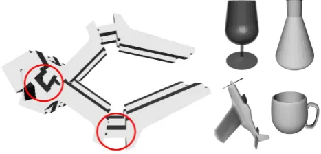
Fig. 2. MODEL OF THE HARVARD HAND AND OBJECT MODELS USED FOR GRASP POOL GENERATION.
The ideal scenario would intuitively be to assemble aglobal optimization problem, allowing the direct computation of the optimal design parameters over the entire grasp pool. How-ever, such a global approach is not always possible to imple-ment.
Consider for example the problem of optimizing the lo-cation of the tendon routing points on their respective links. The effects of the tendon route on the equilibrium condition are encapsulated in the Jacobian of the routing points,Jd. Changing the location of a routing point on a link has a highly non-linear effect onJd. Furthermore, even if we had a linear relationship between tendon route parameters and the routing point Jacobian, the result must be multiplied by the unknown vector of actuation forcesδ. As a result, computing both ac-tuation forcesandoptimal tendon route parameters results in a higher order equality constraint which can not be handled by the same optimization tools.
The general case therefore enables us to quantify a given hand design (by separately computing the quality of each in-dividual grasp in the optimization pool), but not to directly compute a global optimum for the design parameters. We envision two possible solutions to this problem:
• a “numerical” approach, where, for each possible set of design parameter values, each grasp in the pool is analyzed independently. A global measure of grasp stability is com-puted by summing (or averaging) the result for each grasp, and the parameter values that yield the best result are cho-sen.
• a “global optimization” approach, where new constraints are added to the global formulation (containing design pa-rameter values as explicit unknowns) in order to cast it as a solvable optimization problem, such as a Linear or Quadratic Program. Apart from computational efficiency, this method also has the advantage of producing a provable global opti-mum. Its drawback is that the introduction of additional con-straints limits its applicability to a subset of possible hand designs.
Torque ratio
Stiffness ratio
All objects
0.2 0.4 0.6 0.8 1
0.1 0.2 0.3 0.4 0.5 0.6 0.7 0.8 0.9 1
Torque ratio
Stiffness ratio
Glass
0.2 0.4 0.6 0.8 1 0.2
0.4 0.6 0.8 1
Torque ratio
Stiffness ratio
Plane
0.2 0.4 0.6 0.8 1 0.2
0.4 0.6 0.8 1
Torque ratio
Stiffness ratio
Phone
0.2 0.4 0.6 0.8 1 0.2
0.4 0.6 0.8 1
Torque ratio
Stiffness ratio
Mug
0.2 0.4 0.6 0.8 1 0.2
0.4 0.6 0.8 1
Torque ratio
Stiffness ratio
Flask
0.2 0.4 0.6 0.8 1 0.2
0.4 0.6 0.8 1
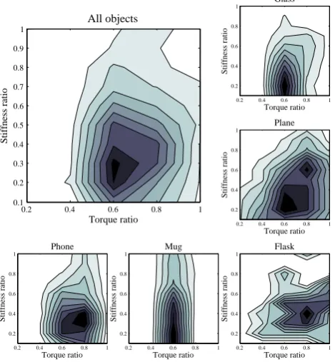
Fig. 3. THE EFFECT OF HAND DESIGN PARAMETERS ON THE LIKELIHOOD OF OBTAINING A STABLE GRASP. A DARKER COLOR MEANS A HIGHER NUMBER OF STABLE GRASPS.
Numerical Optimization
We used the numerical approach to investigate how grasping performance can be improved by changing design parame-ters for the Harvard Hand (Dollar and Howe, 2007). Figure 2 shows theGraspIt! model of this hand, which uses a single actuator to drive eight joints that articulate four fingers. We focused on two design parameters: theactuator torque ratio
between the proximal and distal joints of each finger (circled in the image), and thespring stiffness ratiobetween the same joints. These parameters are determinant for the behavior of the hand, as they affect both the posture of the hand before touching an object and the forces transmitted after contact is made. In particular, we investigated all possible combina-tions ranging from 0.2 to 1.0 (in steps of 0.2) for the torque ratio and from 0.1 to 1.0 (in steps of 0.1) for the stiffness ratio.
The optimization pool consisted of 2000 possible grasps distributed evenly across 5 object models (glass, flask, toy plane, mug and phone receiver). For each object, the set of grasps was created by sampling multiple approach directions on the faces of the object bounding box and aligning the hand with the axes of the box. For each torque and stiffness combi-nation, we used the analysis method presented in the previous section for all the candidate grasps and reported the number Figure 2. Model of the harvard hand and object models used for
grasp pool generation.
for each grasp, and the parameter values that yield the best result are chosen.
– a “global optimization” approach, where new con-straints are added to the global formulation (containing design parameter values as explicit unknowns) in order to cast it as a solvable optimization problem, such as a Linear or Quadratic Program. Apart from computa-tional efficiency, this method also has the advantage of producing a provable global optimum. Its drawback is that the introduction of additional constraints limits its applicability to a subset of possible hand designs.
4.1 Numerical optimization
We used the numerical approach to investigate how grasping performance can be improved by changing design parame-ters for the Harvard Hand (Dollar and Howe, 2007). Figure 2 shows the GraspIt! model of this hand, which uses a single actuator to drive eight joints that articulate four fingers. We focused on two design parameters: the actuator torque ratio between the proximal and distal joints of each finger (circled in the image), and the spring stiffness ratio between the same joints. These parameters are determinant for the behavior of the hand, as they affect both the posture of the hand before touching an object and the forces transmitted after contact is made. In particular, we investigated all possible combina-tions ranging from 0.2 to 1.0 (in steps of 0.2) for the torque ratio and from 0.1 to 1.0 (in steps of 0.1) for the stiffness ratio.
The optimization pool consisted of 2000 possible grasps distributed evenly across 5 object models (glass, flask, toy plane, mug and phone receiver). For each object, the set of grasps was created by sampling multiple approach directions on the faces of the object bounding box and aligning the hand with the axes of the box. For each torque and stiffness combi-nation, we used the analysis method presented in the previous section for all the candidate grasps and reported the number of them that are stable throughout their execution. To enable direct comparison across different objects, each set of results was normalized to a scale of 0 to 1 through division by the
M. Ciocarlie and P. Allen: A constrained optimization framework for compliant underactuated grasping 21 4 M. Ciocarlie and P. Allen: A Constrained Optimization Framework for Compliant Underactuated Grasping
Fig. 2. MODEL OF THE HARVARD HAND AND OBJECT MODELS USED FOR GRASP POOL GENERATION.
The ideal scenario would intuitively be to assemble aglobal optimization problem, allowing the direct computation of the optimal design parameters over the entire grasp pool. How-ever, such a global approach is not always possible to imple-ment.
Consider for example the problem of optimizing the lo-cation of the tendon routing points on their respective links. The effects of the tendon route on the equilibrium condition are encapsulated in the Jacobian of the routing points,Jd. Changing the location of a routing point on a link has a highly non-linear effect onJd. Furthermore, even if we had a linear relationship between tendon route parameters and the routing point Jacobian, the result must be multiplied by the unknown vector of actuation forcesδ. As a result, computing both ac-tuation forcesandoptimal tendon route parameters results in a higher order equality constraint which can not be handled by the same optimization tools.
The general case therefore enables us to quantify a given hand design (by separately computing the quality of each in-dividual grasp in the optimization pool), but not to directly compute a global optimum for the design parameters. We envision two possible solutions to this problem:
• a “numerical” approach, where, for each possible set of design parameter values, each grasp in the pool is analyzed independently. A global measure of grasp stability is com-puted by summing (or averaging) the result for each grasp, and the parameter values that yield the best result are cho-sen.
• a “global optimization” approach, where new constraints are added to the global formulation (containing design pa-rameter values as explicit unknowns) in order to cast it as a solvable optimization problem, such as a Linear or Quadratic Program. Apart from computational efficiency, this method also has the advantage of producing a provable global opti-mum. Its drawback is that the introduction of additional con-straints limits its applicability to a subset of possible hand designs.
Torque ratio
Stiffness ratio
All objects
0.2 0.4 0.6 0.8 1
0.1 0.2 0.3 0.4 0.5 0.6 0.7 0.8 0.9 1 Torque ratio Stiffness ratio Glass
0.2 0.4 0.6 0.8 1 0.2 0.4 0.6 0.8 1 Torque ratio Stiffness ratio Plane
0.2 0.4 0.6 0.8 1 0.2 0.4 0.6 0.8 1 Torque ratio Stiffness ratio Phone
0.2 0.4 0.6 0.8 1 0.2 0.4 0.6 0.8 1 Torque ratio Stiffness ratio Mug
0.2 0.4 0.6 0.8 1 0.2 0.4 0.6 0.8 1 Torque ratio Stiffness ratio Flask
0.2 0.4 0.6 0.8 1 0.2
0.4 0.6 0.8 1
Fig. 3. THE EFFECT OF HAND DESIGN PARAMETERS ON THE LIKELIHOOD OF OBTAINING A STABLE GRASP. A DARKER COLOR MEANS A HIGHER NUMBER OF STABLE GRASPS.
Numerical Optimization
We used the numerical approach to investigate how grasping performance can be improved by changing design parame-ters for the Harvard Hand (Dollar and Howe, 2007). Figure 2 shows theGraspIt!model of this hand, which uses a single actuator to drive eight joints that articulate four fingers. We focused on two design parameters: theactuator torque ratio
between the proximal and distal joints of each finger (circled in the image), and thespring stiffness ratiobetween the same joints. These parameters are determinant for the behavior of the hand, as they affect both the posture of the hand before touching an object and the forces transmitted after contact is made. In particular, we investigated all possible combina-tions ranging from 0.2 to 1.0 (in steps of 0.2) for the torque ratio and from 0.1 to 1.0 (in steps of 0.1) for the stiffness ratio.
The optimization pool consisted of 2000 possible grasps distributed evenly across 5 object models (glass, flask, toy plane, mug and phone receiver). For each object, the set of grasps was created by sampling multiple approach directions on the faces of the object bounding box and aligning the hand with the axes of the box. For each torque and stiffness combi-nation, we used the analysis method presented in the previous section for all the candidate grasps and reported the number Figure 3. The effect of hand design parameters on the likelihood of obtaining a stable grasp. a darker color means a higher number of stable grasps.
maximum number of grasps found for that object. Figure 3 shows the results for each of the objects, as well as their av-erage over the entire set.
The contour maps reveal which areas of the optimization range offer the best performance; in particular they suggest a torque ratio of 0.6 and a stiffness ratio of 0.3. The over-all resemblance between the patterns suggests that the global optimum of the average profile is a good compromise, likely to work well on all objects. However, the patterns exhibit enough variation to illustrate the importance of performing this analysis over a large set of models, spanning a wide range of shapes and grasping scenarios. We note that our torque ratio is in agreement with the value found in the op-timization study carried out before the construction of the Harvard Hand prototype (Dollar and Howe, 2006).
Our analysis consisted of a total of 20 000 grasps for each object (400 candidates for each of the 50 combinations of force and torque ratios); the typical time spent per object was 15 min. This performance suggests the possibility of scaling up to significantly larger test sets as, unlike run-time analysis, off-line optimization can benefit from a time budget of weeks or months, as well as massively parallel computing architec-tures. In addition, it is possible to extend the set of analyzed parameters, including for example link lengths, number of links, etc.
M. Ciocarlie and P. Allen: A Constrained Optimization Framework for Compliant Underactuated Grasping
5
of them that are stable throughout their execution. To enable
direct comparison across different objects, each set of results
was normalized to a scale of 0 to 1 through division by the
maximum number of grasps found for that object. Figure 3
shows the results for each of the objects, as well as their
av-erage over the entire set.
The contour maps reveal which areas of the optimization
range offer the best performance; in particular they suggest
a torque ratio of 0.6 and a stiffness ratio of 0.3. The
over-all resemblance between the patterns suggests that the global
optimum of the average profile is a good compromise, likely
to work well on all objects. However, the patterns exhibit
enough variation to illustrate the importance of performing
this analysis over a large set of models, spanning a wide
range of shapes and grasping scenarios. We note that our
torque ratio is in agreement with the value found in the
op-timization study carried out before the construction of the
Harvard Hand prototype (Dollar and Howe, 2006).
Our analysis consisted of a total of 20,000 grasps for each
object (400 candidates for each of the 50 combinations of
force and torque ratios); the typical time spent per object
was 15 minutes. This performance suggests the possibility of
scaling up to significantly larger test sets as, unlike run-time
analysis, off-line optimization can benefit from a time budget
of weeks or months, as well as massively parallel
comput-ing architectures. In addition, it is possible to extend the set
of analyzed parameters, including for example link lengths,
number of links, etc.
While our results show that this approach is feasible (at
least for a comparable optimization domain), more advanced
numerical optimization algorithms can also be used.
Exam-ples include simulated annealing or gradient ascent using
nu-merical computation of the gradient. While such algorithms
also present disadvantages (like the threat of stopping in local
optima), they are generally better equipped to handle larger
problems. Another option, discussed in detail in the next
sec-tion, avoids exhaustive search by using a different problem
formulation.
Global Optimization
In order to illustrate our global optimization approach to the
hand design problem, we will build up a concrete example,
using as a test bed a two-finger model (which we will refer
to as a gripper, rather than a hand). We will first describe
the starting model, then discuss the reasons for choosing this
particular design.
The basic gripper model is presented in Fig. 4. A single
tendon provides flexion forces for both fingers, which are
co-actuated using a pulley mechanism, similar to the one used
in the Harvard Hand. Note that the pulley allows one
fin-ger to continue flexing even if the other finfin-ger is blocked by
contact with the object. Extension forces are provided by
tendon elastic joints links pulley actuator r li
li li+1
linki
și r
d
jointi
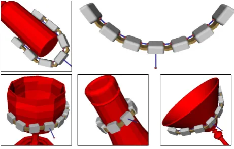
Fig. 4. OVERVIEW AND DETAILED JOINT DESCRIPTION FOR TWO-FINGERED GRIPPER USED AS OPTIMIZATION CASE STUDY.
distal joints to flex even when proximal joints are stopped.
We assume that the kinematic behavior is that of ideal
rev-olute joints, with the center of rotation placed halfway
be-tween the connected links. The tendon itself follows a route
in the flexion-extension plane of the gripper. The essentially
two-dimensional design prevents the links from leaving this
plane without the application of external forces. However,
the tendon route inside this plane is not specified, and is one
of the targets of the optimizations.
Figure 4 also shows in detail the design parameters of the
gripper. The tendon route is determined by the location of
the entry and exit points for each link; more specifically, the
parameter that we use is the distance between the tendon
en-try or exit point and the connection between the link and the
joint. We also make the simplifying assumption that, for a
joint
i
, the exit point from the proximal link and the entry
point in the distal link have the same value for this
parame-ter, which we call
l
i. The current value of the joint is
θ
i.
r
is
the joint radius (shared by all the joints), while the length of
the links is denoted by
d
.
The reason for using this design and formulation is that
they yield a compact and, more importantly, linear
relation-ship between the construction parameters and the joint forces
applied through the tendon. If we consider the parameter
vector
p
= [
l
0l
1l
2l
3l
4l
5r d
]
, we obtain a relationship of
the form:
τ
=
δ
(
Bp
+
a
) +
θk
(9)
where the matrix
B
∈ R
8x8and the vector
a
∈ R
8depend
only on the joint values
θ
0...θ
5. A sketch for the derivation
Figure 4.Overview and detailed joint description for two-fingered gripper used as optimization case study.
While our results show that this approach is feasible (at least for a comparable optimization domain), more advanced numerical optimization algorithms can also be used. Exam-ples include simulated annealing or gradient ascent using nu-merical computation of the gradient. While such algorithms also present disadvantages (like the threat of stopping in local optima), they are generally better equipped to handle larger problems. Another option, discussed in detail in the next sec-tion, avoids exhaustive search by using a different problem formulation.
4.2 Global optimization
In order to illustrate our global optimization approach to the hand design problem, we will build up a concrete example, using as a test bed a two-finger model (which we will refer to as a gripper, rather than a hand). We will first describe the starting model, then discuss the reasons for choosing this particular design.
The basic gripper model is presented in Fig. 4. A single tendon provides flexion forces for both fingers, which are co-actuated using a pulley mechanism, similar to the one used in the Harvard Hand. Note that the pulley allows one fin-ger to continue flexing even if the other finfin-ger is blocked by contact with the object. Extension forces are provided by spring-like joints. In practice, these joints can be constructed using a compliant, rubber-like material; this design enables distal joints to flex even when proximal joints are stopped. We assume that the kinematic behavior is that of ideal rev-olute joints, with the center of rotation placed halfway be-tween the connected links. The tendon itself follows a route in the flexion-extension plane of the gripper. The essentially
22 M. Ciocarlie and P. Allen: A constrained optimization framework for compliant underactuated grasping two-dimensional design prevents the links from leaving this
plane without the application of external forces. However, the tendon route inside this plane is not specified, and is one of the targets of the optimizations.
Figure 4 also shows in detail the design parameters of the gripper. The tendon route is determined by the location of the entry and exit points for each link; more specifically, the parameter that we use is the distance between the tendon en-try or exit point and the connection between the link and the joint. We also make the simplifying assumption that, for a joint i, the exit point from the proximal link and the entry point in the distal link have the same value for this parame-ter, which we call li. The current value of the joint isθi. r is
the joint radius (shared by all the joints), while the length of the links is denoted by d.
The reason for using this design and formulation is that they yield a compact and, more importantly, linear relation-ship between the construction parameters and the joint forces applied through the tendon. If we consider the parameter vector p=[l0l1l2l3l4l5r d], we obtain a relationship of the form:
τ=δ(B p+a)+θk (9)
where the matrix B∈ R8x8and the vector a∈ R8depend only on the joint valuesθ0...θ5. A sketch for the derivation of these matrices is presented in the Appendix. Furthermore, since we are using a single tendon, we can normalize its value without loss of generality toδ=1N. The joint force relation-ship, and by extension the grasp equilibrium conditions, are now linear in all of the unknowns.
Having established the general characteristics of the grip-per, the next step was to generate a pool of grasps over which to optimize its performance. We created a kinematic model of the gripper for the GraspIt! environment, assuming each joint could be controlled independently. Then, using the in-teraction tools in the simulator, we manually specified a num-ber of grasps over a set of 3-D models of common household objects. The set comprised 70 grasps distributed across 15 objects; the process is illustrated in Fig. 5. Each grasp was defined by the set of gripper joint angles, the location of the contacts on each link, and the contact surface normals, re-sulting in a purely “geometric” description of a grasp, with no reference to the actuation mechanism.
Most of the grasps in the pool used different postures for the two fingers of the gripper. We added to the set the “trans-pose” of each grasp, obtained by rotating the gripper by 180◦
around the wrist roll axis, reversing the roles of the left and right finger. The complete optimization pool thus comprised 140 grasps. The inclusion of the transposed grasps also en-sured that the final optimized parameters, presented in the next section, where symmetrical, with identical results for both fingers.
A key restriction during the creation of the optimization pool was that all the grasps therein were required to have form-closure. GraspIt! integrates a number of analysis tools
6 M. Ciocarlie and P. Allen: A Constrained Optimization Framework for Compliant Underactuated Grasping
Fig. 5. GRIPPER MODEL FOR GRASPIT! AND EXAMPLES OF GRASPS FROM THE OPTIMIZATION POOL.
without loss of generality toδ= 1N. The joint force relation-ship, and by extension the grasp equilibrium conditions, are now linear in all of the unknowns.
Having established the general characteristics of the grip-per, the next step was to generate a pool of grasps over which to optimize its performance. We created a kinematic model of the gripper for theGraspIt! environment,assuming each joint could be controlled independently. Then, using the in-teraction tools in the simulator, we manually specified a num-ber of grasps over a set of 3D models of common household objects. The set comprised 70 grasps distributed across 15 objects; the process is illustrated in Fig. 5. Each grasp was defined by the set of gripper joint angles, the location of the contacts on each link, and the contact surface normals, re-sulting in a purely ”geometric” description of a grasp, with no reference to the actuation mechanism.
Most of the grasps in the pool used different postures for the two fingers of the gripper. We added to the set the ”trans-pose” of each grasp, obtained by rotating the gripper by 180◦ around the wrist roll axis, reversing the roles of the left and right finger. The complete optimization pool thus comprised 140 grasps. The inclusion of the transposed grasps also en-sured that the final optimized parameters, presented in the next section, where symmetrical, with identical results for both fingers.
A key restriction during the creation of the optimization pool was that all the grasps therein were required to have form-closure.GraspIt!integrates a number of analysis tools for establishing the form-closure property by building the Grasp Wrench Space, as described by Ferrari and Canny (1992). This formulation is equivalent to the ability of a set of contacts to apply a null resulting wrench on the object while satisfying contact friction constraints, but disregarding any kinematic or actuation constraints.
For each grasp in our optimization pool, we can apply the equilibrium formulation using the actuation mechanism
model described earlier in this section:
JcjT
Djβj=Bjp+aj+θjk (10)
Gjβj= 0 (11)
βj, Fjβj≥0 (12)
where we use the superscriptj to denote the index number of the particular grasp from the optimization pool that we are referring to. The unknowns are the grasp contact forcesβj, the hand parameter vectorpand the vector of joint spring stiffnessesk. Note thatpandkdo not have a superscript as they are shared between all the grasps in the pool.
To obtain a global optimization problem, we assemble these relationships in block form over the entire pool of grasps. The matrices for individual grasps(Jj
c)TDj, Bj,
θj,GjandFjare assembled in block diagonal form in the matricesJ˜T
c D˜,B˜,θ˜,G˜andF˜, respectively. The vectorsβj andajare assembled in block columns in the vectorsβ˜and ˜
a. Finally, the joint equilibrium condition (10) assembled for all the grasps in the pool becomes the optimization objective:
minimize h ˜ JT
cD˜ −B˜ −θ˜
i ˜ β p k
−a˜ subject to: ˜
Gβ˜= 0 (13)
˜
β, F˜β˜≥0 (14)
pmin ≤ p≤pmax (15)
kmin ≤ k≤kmax (16)
The minimum and maximum values for the construction pa-rameterspandkcan be set to reflect constraints in the phys-ical construction of the gripper, as we will show in the next section.
We note that the result is again a convex Quadratic Pro-gram that, by construction, always accepts a solution: con-straints (13) and (14) are equivalent to each individual grasp having form-closure independently of the actuation mecha-nism, which we ensured by building our grasp pool accord-ingly. As a result, the problem can be solved and a global optimum can be computed.
Construction of an Optimized Gripper
The final step of using our framework was physical construc-tion of a gripper according to the results of the optimizaconstruc-tion. This required setting limits for the optimized parameters that could be implemented in practice. In particular, we used a limit of -5mm≤li≤5mm∀i to ensure that the tendon route was inside the physical volume of each link.
Using a fixed grasp pool affects the parameters that can be part of the analysis: if the values of r (joint radius) and d (link length) can change as part of the optimization, the result can be kinematically different than the model used for the generation of the grasp pool. Taking this aspect into account, Figure 5.Gripper model for graspit! and examples of grasps from
the optimization pool.
for establishing the form-closure property by building the Grasp Wrench Space, as described by Ferrari and Canny (1992). This formulation is equivalent to the ability of a set of contacts to apply a null resulting wrench on the object while satisfying contact friction constraints, but disregarding any kinematic or actuation constraints.
For each grasp in our optimization pool, we can apply the equilibrium formulation using the actuation mechanism model described earlier in this section:
Jcj
T
Djβj = Bjp+aj+θjk (10)
Gjβj = 0 (11)
βj, Fjβj ≥ 0 (12)
where we use the superscript j to denote the index number of the particular grasp from the optimization pool that we are referring to. The unknowns are the grasp contact forcesβj, the hand parameter vector p and the vector of joint spring stiffnesses k. Note that p and k do not have a superscript as they are shared between all the grasps in the pool.
To obtain a global optimization problem, we assemble these relationships in block form over the entire pool of grasps. The matrices for individual grasps (Jcj)TDj, Bj,θj,
Gjand Fjare assembled in block diagonal form in the
matri-ces ˜JT
cD, ˜˜ B, ˜θ, ˜G and ˜F, respectively. The vectorsβjand aj
are assembled in block columns in the vectors ˜βand ˜a. Fi-nally, the joint equilibrium condition (10) assembled for all the grasps in the pool becomes the optimization objective:
minimize h˜ JT
cD˜ −B˜ −θ˜
i ˜ β p k −˜a subject to: ˜
G ˜β = 0 (13)
˜
β, F ˜˜β ≥ 0 (14)
pmin ≤ p ≤ pmax (15)
kmin ≤ k ≤ kmax (16)
M. Ciocarlie and P. Allen: A constrained optimization framework for compliant underactuated grasping 23 The minimum and maximum values for the construction
pa-rameters p and k can be set to reflect constraints in the phys-ical construction of the gripper, as we will show in the next section.
We note that the result is again a convex Quadratic Pro-gram that, by construction, always accepts a solution: con-straints (13) and (14) are equivalent to each individual grasp having form-closure independently of the actuation mecha-nism, which we ensured by building our grasp pool accord-ingly. As a result, the problem can be solved and a global optimum can be computed.
4.3 Construction of an optimized gripper
The final step of using our framework was physical construc-tion of a gripper according to the results of the optimizaconstruc-tion. This required setting limits for the optimized parameters that could be implemented in practice. In particular, we used a limit of−5 mm≤li≤5 mm∀i to ensure that the tendon route
was inside the physical volume of each link.
Using a fixed grasp pool affects the parameters that can be part of the analysis: if the values of r (joint radius) and d (link length) can change as part of the optimization, the result can be kinematically different than the model used for the generation of the grasp pool. Taking this aspect into account, we performed two optimizations. For the first one (referred to as Optimization 1), we fixed the values to r=5 mm and d=20 mm. For the second one (Optimization 2) we set the limits 3 mm≤r≤10 mm and 15 mm≤d≤22 mm. We also added the constraint r+d=25 mm, to ensure that the overall length of the fingers would not change.
The joint stiffness levels require additional discussion, as there are two cases to consider. First, during the early stages of the grasp, spring forces and tendon forces play equal parts in the process. Once the fingers are closed however, tendon forces can be increased arbitrarily, while spring forces do not change if the grasp is stable and no joint movement occurs. In the limit, tendon forces dominate to the point that spring forces become negligible. An ideal grasp would be stable in both of these phases. For each of the two optimizations, we used the following convention. Tendon route values were derived by solving the optimization problem without joint springs, in an attempt to ensure grasp stability in the limit. The resulting values were then plugged back into the opti-mization, in order to compute spring stiffness values, using as limits 1.0 Nmmrad−1≤k
i≤2.0 Nmmrad−1.
The dual nature of joint stiffness vs. tendon force opti-mization presents interesting possibilities and requires more detailed exploration than presented here. In particular, we envision a case where joint springs are used to determine the postures that the hand achieves in “free motion”, thus aff ect-ing pre-grasp behavior, while tendon routes are optimized for stable grasps in the limit. The transition between these two phases will present additional challenges to address. We
be-M. Ciocarlie and P. Allen: A Constrained Optimization Framework for Compliant Underactuated Grasping 7
0 0.2 0.4 0.6 0.8 1
0 20 40 60 80 100 120
A
v
g.
j
o
in
t unb
al
an
ce
d
to
rq
ue (
N
m
m
)
Grasp number (ordered in increasing quality value) Ad-hoc Optim. 1 Optim. 2
Fig. 6. UNBALANCED JOINT FORCES OVER THE SET OF GRASPS IN THE OPTIMIZATION POOL.
Table 1.RESULTS OF GRIPPER DESIGN OPTIMIZATION.
lo l1 l2 ko k1 k2 r d
Ad-hoc 5.0 5.0 5.0 1.0 1.0 1.0 5.0 20.0 Optimization 1 5.0 5.0 1.72 1.0 1.0 2.0 5.0 20.0 Optimization 2 5.0 4.64 1.02 1.0 1.0 2.0 7.89 17.11
we performed two optimizations. For the first one (referred to as Optimization 1), we fixed the values to r=5mmand d=20mm. For the second one (Optimization 2) we set the limits 3mm≤r≤10mmand 15mm≤d≤22mm. We also added the constraint r+d=25mm, to ensure that the overall length of the fingers would not change.
The joint stiffness levels require additional discussion, as there are two cases to consider. First, during the early stages of the grasp, spring forces and tendon forces play equal parts in the process. Once the fingers are closed however, tendon forces can be increased arbitrarily, while spring forces do not change if the grasp is stable and no joint movement occurs. In the limit, tendon forces dominate to the point that spring forces become negligible. An ideal grasp would be stable in both of these phases. For each of the two optimizations, we used the following convention. Tendon route values were derived by solving the optimization problem without joint springs, in an attempt to ensure grasp stability in the limit. The resulting values were then plugged back into the opti-mization, in order to compute spring stiffness values, using as limits 1.0Nmmrad−1≤k
i≤2.0Nmmrad−1.
The dual nature of joint stiffness vs. tendon force opti-mization presents interesting possibilities and requires more detailed exploration than presented here. In particular, we envision a case where joint springs are used to determine the postures that the hand achieves in “free motion”, thus affect-ing pre-grasp behavior, while tendon routes are optimized for stable grasps in the limit. The transition between these two phases will present additional challenges to address. We be-lieve that the optimization framework presented here can be a first step in this direction.
Fig. 7. TWO GRASPS (CENTERED AND ASYMMETRICAL) EXECUTED WITH THE PROTOTYPE GRIPPER.
The results of the optimizations are shown in Table 1. We only show the values for one of the fingers, since, as men-tioned before, the results for the other finger are symmetrical. For a quantitative analysis of the computed optimal configu-rations, we compared them against an ad-hoc parameter set, withli=5mmandki=1Nmmrad−1∀i. The comparison cri-terion was the level of unbalanced joint forces for each grasp in the limit case. The results are shown in Fig. 6. We no-tice that the optimized configurations provide significantly more stable grasps across the optimization pool. In addition, allowing a change in the link length and joint radius pro-vides additional stability, but the gains are diminished com-pared to the case where these parameters are fixed. The total time spent formulating and solving each optimization prob-lem was less than a minute, using a commodity desktop com-puter. This suggests the future possibility of scaling to much larger grasp optimization pools.
We constructed a prototype gripper using the results of Optimization 1. The links were built using a Stratasys FDM rapid prototyping machine, and assembled using elas-tic joints cut from a sheet of hard rubber. Each link contained a tendon route with the entry and exit points set according to the optimization results. The width of the strip of rubber was varied for each joint to provide the desired stiffness ra-tios. As this prototype is intended as a proof-of-concept for the kinematic configuration and design parameters, no motor or sensors were installed; instead, actuation was performed manually.
We found that the prototype gripper is capable of a wide range of grasping tasks and does not require precise posi-tioning relative to the target object. Its passive adaptation ability is exemplified in Fig. 7, which shows the execution of two grasps. The first one starts from a centered position and leads to relatively similar joint values for both fingers. In contrast, the second grasp requires the joints to conform to an asymmetrical, irregular shape. Both grasps were executed successfully. Figure 8 attempts to provide an illustration of the spectrum of grasps that can be carried out with this grip-per. All of the presented grasps were executed successfully and the object was securely lifted off the table, with very lit-Figure 6. Unbalanced joint forces over the set of grasps in the
optimization pool.
Table 1.Results of gripper design optimization.
lo l1 l2 ko k1 k2 r d
Ad-hoc 5.0 5.0 5.0 1.0 1.0 1.0 5.0 20.0 Optimization 1 5.0 5.0 1.72 1.0 1.0 2.0 5.0 20.0 Optimization 2 5.0 4.64 1.02 1.0 1.0 2.0 7.89 17.11
lieve that the optimization framework presented here can be a first step in this direction.
The results of the optimizations are shown in Table 1. We only show the values for one of the fingers, since, as men-tioned before, the results for the other finger are symmetrical. For a quantitative analysis of the computed optimal configu-rations, we compared them against an ad-hoc parameter set, with li=5 mm and ki=1 Nmmrad−1∀i. The comparison
cri-terion was the level of unbalanced joint forces for each grasp in the limit case. The results are shown in Fig. 6. We no-tice that the optimized configurations provide significantly more stable grasps across the optimization pool. In addition, allowing a change in the link length and joint radius pro-vides additional stability, but the gains are diminished com-pared to the case where these parameters are fixed. The total time spent formulating and solving each optimization prob-lem was less than a minute, using a commodity desktop com-puter. This suggests the future possibility of scaling to much larger grasp optimization pools.
24 M. Ciocarlie and P. Allen: A constrained optimization framework for compliant underactuated grasping M. Ciocarlie and P. Allen: A Constrained Optimization Framework for Compliant Underactuated Grasping 7
0 0.2 0.4 0.6 0.8 1
0 20 40 60 80 100 120
A
v
g.
j
o
in
t unb
al
an
ce
d
to
rq
ue (
N
m
m
)
Grasp number (ordered in increasing quality value) Ad-hoc Optim. 1 Optim. 2
Fig. 6. UNBALANCED JOINT FORCES OVER THE SET OF GRASPS IN THE OPTIMIZATION POOL.
Table 1.RESULTS OF GRIPPER DESIGN OPTIMIZATION.
lo l1 l2 ko k1 k2 r d
Ad-hoc 5.0 5.0 5.0 1.0 1.0 1.0 5.0 20.0 Optimization 1 5.0 5.0 1.72 1.0 1.0 2.0 5.0 20.0 Optimization 2 5.0 4.64 1.02 1.0 1.0 2.0 7.89 17.11
we performed two optimizations. For the first one (referred to as Optimization 1), we fixed the values to r=5mm and d=20mm. For the second one (Optimization 2) we set the limits 3mm≤r≤10mmand 15mm≤d≤22mm. We also added the constraint r+d=25mm, to ensure that the overall length of the fingers would not change.
The joint stiffness levels require additional discussion, as there are two cases to consider. First, during the early stages of the grasp, spring forces and tendon forces play equal parts in the process. Once the fingers are closed however, tendon forces can be increased arbitrarily, while spring forces do not change if the grasp is stable and no joint movement occurs. In the limit, tendon forces dominate to the point that spring forces become negligible. An ideal grasp would be stable in both of these phases. For each of the two optimizations, we used the following convention. Tendon route values were derived by solving the optimization problem without joint springs, in an attempt to ensure grasp stability in the limit. The resulting values were then plugged back into the opti-mization, in order to compute spring stiffness values, using as limits 1.0Nmmrad−1≤ki≤2.0Nmmrad−1.
The dual nature of joint stiffness vs. tendon force opti-mization presents interesting possibilities and requires more detailed exploration than presented here. In particular, we envision a case where joint springs are used to determine the postures that the hand achieves in “free motion”, thus affect-ing pre-grasp behavior, while tendon routes are optimized for stable grasps in the limit. The transition between these two phases will present additional challenges to address. We be-lieve that the optimization framework presented here can be a first step in this direction.
Fig. 7. TWO GRASPS (CENTERED AND ASYMMETRICAL) EXECUTED WITH THE PROTOTYPE GRIPPER.
The results of the optimizations are shown in Table 1. We only show the values for one of the fingers, since, as men-tioned before, the results for the other finger are symmetrical. For a quantitative analysis of the computed optimal configu-rations, we compared them against an ad-hoc parameter set, withli=5mmandki=1Nmmrad−1∀i. The comparison cri-terion was the level of unbalanced joint forces for each grasp in the limit case. The results are shown in Fig. 6. We no-tice that the optimized configurations provide significantly more stable grasps across the optimization pool. In addition, allowing a change in the link length and joint radius pro-vides additional stability, but the gains are diminished com-pared to the case where these parameters are fixed. The total time spent formulating and solving each optimization prob-lem was less than a minute, using a commodity desktop com-puter. This suggests the future possibility of scaling to much larger grasp optimization pools.
We constructed a prototype gripper using the results of Optimization 1. The links were built using a Stratasys FDM rapid prototyping machine, and assembled using elas-tic joints cut from a sheet of hard rubber. Each link contained a tendon route with the entry and exit points set according to the optimization results. The width of the strip of rubber was varied for each joint to provide the desired stiffness ra-tios. As this prototype is intended as a proof-of-concept for the kinematic configuration and design parameters, no motor or sensors were installed; instead, actuation was performed manually.
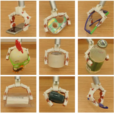
We found that the prototype gripper is capable of a wide range of grasping tasks and does not require precise posi-tioning relative to the target object. Its passive adaptation ability is exemplified in Fig. 7, which shows the execution of two grasps. The first one starts from a centered position and leads to relatively similar joint values for both fingers. In contrast, the second grasp requires the joints to conform to an asymmetrical, irregular shape. Both grasps were executed successfully. Figure 8 attempts to provide an illustration of the spectrum of grasps that can be carried out with this grip-per. All of the presented grasps were executed successfully and the object was securely lifted off the table, with very lit-Figure 7. Two grasps (centered and asymmetrical) executed with the prototype gripper.
We found that the prototype gripper is capable of a wide range of grasping tasks and does not require precise posi-tioning relative to the target object. Its passive adaptation ability is exemplified in Fig. 7, which shows the execution of two grasps. The first one starts from a centered position and leads to relatively similar joint values for both fingers. In contrast, the second grasp requires the joints to conform to an asymmetrical, irregular shape. Both grasps were executed successfully. Figure 8 attempts to provide an illustration of the spectrum of grasps that can be carried out with this grip-per. All of the presented grasps were executed successfully and the object was securely lifted offthe table, with very lit-tle time or effort spent positioning the gripper relative to the target.
5 Discussion and conclusions
A qualitative analysis of the optimization results can start from the observation that the prototype gripper is capable of executing both fingertip grasps (of varying finger spans) and enveloping grasps (of both regular and irregular shapes). Intuitively, fingertip grasps require relatively low torques on the distal joints, so that fingertip forces are in opposition, rather than oriented towards the palm. Conversely, larger torques on the distal joints benefit enveloping grasps; as a result, the optimization process was required to combine two somewhat opposing goals. The results indicate that the solu-tion indeed enables both kinds of grasps, but the distal joint is both stiffer and less powerful than the proximal ones. In fact, our optimization framework achieves this characteris-tic by “saturating” many of the hand parameters, which take either the minimum or maximum value allowed.
In this sense, the result of the optimization could be inter-preted as meaning that the addition of a third link to the grip-per provides little benefit. The resulting gripgrip-per comes close to a model with two links per finger, a design also confirmed in the optimization studies of Dollar and Howe (2006). We believe that this is the type of analysis that our framework is natively suited for: in future iterations, we can directly com-pare two- and three-link models, and compute a numerical
8 M. Ciocarlie and P. Allen: A Constrained Optimization Framework for Compliant Underactuated Grasping
tle time or effort spent positioning the gripper relative to the target.
5 Discussion and Conclusions
A qualitative analysis of the optimization results can start from the observation that the prototype gripper is capable of executing both fingertip grasps (of varying finger spans) and enveloping grasps (of both regular and irregular shapes). Intuitively, fingertip grasps require relatively low torques on the distal joints, so that fingertip forces are in opposition, rather than oriented towards the palm. Conversely, larger torques on the distal joints benefit enveloping grasps; as a result, the optimization process was required to combine two somewhat opposing goals. The results indicate that the solu-tion indeed enables both kinds of grasps, but the distal joint is both stiffer and less powerful than the proximal ones. In fact, our optimization framework achieves this characteris-tic by “saturating” many of the hand parameters, which take either the minimum or maximum value allowed.
In this sense, the result of the optimization could be inter-preted as meaning that the addition of a third link to the grip-per provides little benefit. The resulting gripgrip-per comes close to a model with two links per finger, a design also confirmed in the optimization studies of Dollar and Howe (2006). We believe that this is the type of analysis that our framework is natively suited for: in future iterations, we can directly com-pare two- and three-link models, and compute anumerical measureof the benefit provided by the additional link. The relatively simple two-fingered design that we used here al-lows an intuitive understanding of the design choices (which makes it well suited for initial testing and proof-of-concept implementations). However, for more complex models, em-pirical analysis becomes unfeasible, and quantitative tools, such as the one presented here, can prove more valuable.
We also believe that future hand design studies will consist of a combination of exhaustive search and optimization prob-lems for which more efficient algorithms are available. The space of possible hand designs, and implicitly the domain of parameters to be optimized, is practically limitless. Virtually any hand design ever proposed involves some compromise of ad-hoc decisions vs. informed, optimized parameter choices. In our case, we have discussed aspects such as tendon routes and joint stiffness. However, by moving up in the scale at which we are analyzing the hand, we can uncover many more design decisions, which we assumed as given: number and configuration of links, kinematic chains,etc. Some of these will likely prove impossible to encapsulate in a solvable op-timization problem, thus some contribution from numerical approaches will be unavoidable.
An interesting aspect concerns the on-line algorithms that are used to control the hand during grasping tasks. Tradition-ally, these algorithms have been designed after the hand was constructed, carefully tuned to extract the best performance
Fig. 8. GRASPS EXECUTED WITH THE PROTOTYPE GRIP-PER.
from a given mechanical design. Off-line hand optimization enables the opposite approach: the hand mechanism is de-signed to suit a particular algorithm. The same applies to sensor arrays: we can build a hand that is optimized for the types of grasps that we can expect to perform based on data from a certain sensor. In this way, the hand is intrinsically equipped to handle the shortcomings of the input data. Over-all, it seems natural to ask: what comes first, the hand or the algorithm?
As robots with the ability to operate in unstructured set-tings are constantly evolving, we believe that research on adaptive and underactuated designs has the potential to ul-timately provide us with inexpensive and easy-to-build, yet effective robotic hands for a variety of applications in human environments.
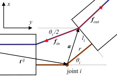
Appendix A Derivation of Gripper Joint Torque
In order to sketch the derivation for the relationship between the tendon route parameters and the resulting joint torques, we start by focusing on how tendon entry and exit points on linkiaffect the torque applied at jointj. Using the notation shown in Fig. A1, we use jointias our reference coordinate frame, and assume that the translation from jointjto jointi istij= [tij
x tijy]T.
In general, for any point where a tendon changes direction, such as the link entry point in the figure, the force applied to the link is the resultant of the total tendon force applied in both the initial and the changed direction, orf=fin+fout. We note that||fin||=||fout||=δ. However, since we nor-Figure 8.Grasps executed with the prototype gripper.
measure of the benefit provided by the additional link. The relatively simple two-fingered design that we used here al-lows an intuitive understanding of the design choices (which makes it well suited for initial testing and proof-of-concept implementations). However, for more complex models, em-pirical analysis becomes unfeasible, and quantitative tools, such as the one presented here, can prove more valuable.
We also believe that future hand design studies will consist of a combination of exhaustive search and optimization prob-lems for which more efficient algorithms are available. The space of possible hand designs, and implicitly the domain of parameters to be optimized, is practically limitless. Virtually any hand design ever proposed involves some compromise of ad-hoc decisions vs. informed, optimized parameter choices. In our case, we have discussed aspects such as tendon routes and joint stiffness. However, by moving up in the scale at which we are analyzing the hand, we can uncover many more design decisions, which we assumed as given: number and configuration of links, kinematic chains, etc. Some of these will likely prove impossible to encapsulate in a solvable op-timization problem, thus some contribution from numerical approaches will be unavoidable.
An interesting aspect concerns the on-line algorithms that are used to control the hand during grasping tasks. Tradition-ally, these algorithms have been designed after the hand was constructed, carefully tuned to extract the best performance from a given mechanical design. Off-line hand optimization enables the opposite approach: the hand mechanism is de-signed to suit a particular algorithm. The same applies to sensor arrays: we can build a hand that is optimized for the types of grasps that we can expect to perform based on data
M. Ciocarlie and P. Allen: A constrained optimization framework for compliant underactuated grasping 25
M. Ciocarlie and P. Allen: A Constrained Optimization Framework for Compliant Underactuated Grasping
9
ș
i/2
r
l
ijoint
i
ș
it
ijf
inf
outa
x
y
Fig. A1.
Torque computation for tendon entry point
malize tendon force to
δ
= 1
we can omit it from the
com-putations. We then obtain the torque applied around a given
joint by cross-product with the joint moment arm. Using this
notation, the torque around joint
j
applied at the tendon entry
point in link
i
is:
τ
entry
ij= (
t
ij+
a
)
×
(
f
in+
f
out)
(A1)
=
"
t
ijxt
ijy#
+
cosθ
isinθ
i−
sinθ
icosθ
il
ir
!
×
×
−
sin
(
θ
i/
2)
−
cos
(
θ
i/
2)
+
sinθ
icosθ
i(A2)
Through a similar computation, using the notation from
Figs. 4 and A1, we can compute the torque applied at the
tendon exit point from link
i
as:
τ
ijexit
=
"
t
ijxt
ijy#
+
cosθ
isinθ
i−
sinθ
icosθ
il
i+1r
+
d
!
×
×
sin
(
θ
i+
θ
i+1/
2)
cos
(
θ
i+
θ
i+1/
2)
+
−
sinθ
i−
cosθ
i(A3)
If
l
i6
=
l
i+1, the tendon must also change direction
some-where inside link
i
. The resulting torque is simply:
τ
ijchange
=
l
i+1−
l
i(A4)
All of these contributions are added to obtain the total
torque applied on joint
j
due to tendon routing points on link
i
. Finally, the computation above is repeated for all desired
combinations of
i
and
j
. By explicitly computing cross
prod-ucts as
u
×
v
= [
v
y−
v
x][
u
xu
y]
Twe obtain the respective
entries in the matrix
B
and the vector
a
, which are then
as-sembled in the linear relationship
τ
tendon
=
B
(
θ
)
p
+
a
(
θ
)
(A5)
which can then integrated in the complete grasp formulation
presented in the paper.
References
Birglen, L., Laliberte, T., and Gosselin, C.: Underactuated Robotic
Hands, Springer Tracts in Adv. Robotics, 2008.
Dollar, A. and Howe, R.: Joint Coupling Design of Underactuated
Grippers, in: 30th Mech. and Robotics Conf., 2006.
Dollar, A. and Howe, R.: Simple, Robust Autonomous Grasping
in Unstructured Environments, in: IEEE Intl. Conf. on Robotics
and Automation, 2007.
Ferrari, C. and Canny, J.: Planning optimal grasps, in: IEEE Intl.
Conf. on Robotics and Automation, 1992.
Gosselin, C., Laliberte, T., and Degoulange, T.: Underactuated
robotic hand, in: Video Proceedings of the IEEE Intl. Conf. on
Robotics and Automation, 1998.
Gosselin, C., Pelletier, F., and Laliberte, T.: An Anthropomorphic
Underactuated Robotic Hand with 15 Dofs and a Single Actuator,
in: IEEE Intl. Conf. on Robotics and Automation, 2008.
Hirose, S. and Umetani, Y.: The development of soft gripper for
the versatile robot hand, Mechanism and Machine Theory, 13,
351–358, 1978.
Kwak, S. D., Blankevoort, L., and Ateshian, G.: A mathematical
formulation for 3D quasi-static multibody models of diarthrodial
joints, Computer Meth. in Biomech. and Biomed. Eng., 3, 41–64,
2000.
Laliberte, T., Birglen, L., and Gosselin, C. M.: Underactuation in
robotic grasping hands, Machine Intelligence & Robotic Control,
4, 1–11, 2002.
Miller, A. and Allen, P. K.: GraspIt!: a versatile simulator for
robotic grasping, IEEE Robotics and Automation Magazine, 11,
110–122, 2004.
Mosek: Mosek ApS Denmark, http://www.mosek.com.
Prattichizzo, D. and Trinkle, J. C.: Grasping, in: Springer
Hand-book of Robotics, pp. 671–700, Springer, 2008.
Ulrich, N., Paul, R., and Bajcsy, R.: A medium-complexity
compli-ant end effector, in: IEEE Intl. Conf. on Robotics and
Automa-tion, 1