http://www.sciencepublishinggroup.com/j/ajma doi: 10.11648/j.ajma.20190702.12
ISSN: 2376-6115 (Print); ISSN: 2376-6131 (Online)
Strength Performance Analysis and Improvement of Engine
Mounting Bracket for a Commercial Vehicle
Lv Lin
*, Wang Jizhong, Chen Shuai
Qingdao University of Technology, College of Machinery and Automobile, Qingdao, China
Email address:
*Corresponding author
To cite this article:
Lv Lin, Wang Jizhong, Chen Shuai. Strength Performance Analysis and Improvement of Engine Mounting Bracket for a Commercial Vehicle. American Journal of Mechanics and Applications. Vol. 7, No. 2, 2019, pp. 21-29. doi: 10.11648/j.ajma.20190702.12
Received: May 11, 2019; Accepted: June 26, 2019; Published: July 17, 2019
Abstract:
With the rapid development of the automotive industry and the increasing demand of consumers for the quality of automotive products, improving the reliability of automotive products has become the "top priority" of enterprises. While improving the reliability level of engine mounting bracket for commercial vehicles, it can not reduce the mechanical strength performance of the structure. Therefore, it is of practical significance to optimize the structure and study the reliability of the mounting bracket. The engine mounting bracket mainly supports the weight of the engine. According to the design space and process requirements, the topology optimization design is carried out to find the most reasonable material distribution. Structural optimization of mounting bracket can be demonstrated by different schemes in conceptual design stage, and verified by finite element analysis and strength test. Among many complex factors affecting structural reliability, product design is the most fundamental one. The design determines the reliability of engine mounting bracket, and the defects left in the design can not be completely solved in production and use. During the design and development of a commercial vehicle, the engine mounting bracket broke during road test. Through macro-analysis of the fracture site, it is preliminarily determined that the suspension bracket system suffers from rapid fracture due to excessive load under driving conditions, resulting in stress concentration. The finite element model of powertrain mounting bracket is established, the strength of mounting bracket is analyzed, and the structure of engine bracket is improved according to its stress distribution and processing requirements. Comparing the performance of engine mounting bracket before and after improvement, it shows that the strength of engine mounting bracket has been improved obviously, and the weight has been reduced effectively. It provides an important reference for the strength performance design of engine mounting bracket.Keywords:
Engine Mounting Bracket, Finite Element Analysis, Structural Improvement, Strength1. Introduction
It is well known that the engine bracket, also known as the powertrain mounting bracket, is located in the chassis of the car responsible for connecting the engine and the body (or sub-frame) parts. In automobile driving, the mounting bracket can tighten and support the engine, and can buffer the reciprocating inertia force excitation when the engine works [1]. Its strength and stiffness are closely related to driving comfort and safety. The modal natural frequency of engine bracket has a great influence on the NVH performance of the vehicle, and its shape, size and material properties also have a great influence on the layout of the vehicle and fuel economy
[2]. Therefore, the engine bracket not only has enough strength and stiffness, but also its size should match the layout of the frame and engine, and on this basis, meet the requirements of vehicle lightweight as far as possible.
22 Lv Lin et al.: Strength Performance Analysis and Improvement of Engine Mounting Bracket for a Commercial Vehicle
There are many factors affecting fretting fatigue, such as stress distribution in contact area under alternating load, nominal contact pressure of contact surface, friction coefficient between contact surfaces, etc. Hu Rongrong analyzed the strength of the suspension bracket under six working conditions and compared it with the whole road test [4]. Bai Kunhai established the engine bracket model by finite element method, and analyzed the strength of the engine bracket under eight working conditions. The strength requirement of the engine bracket was obtained [5]. Zhao Lijie calculates and analyses the strength and mode of the mounting bracket by means of finite element analysis software, and carries out fatigue and failure tests on it [6].
Structural optimization design is an important part of CAE technology. It has natural advantages in product structure design and is widely used in product design [7]. In the conceptual design stage, 80% of the cost is usually determined. In this important stage, topology optimization finds the best material distribution within the given product space, guarantees the performance and provides design ideas. This new design process is also called ODDP (Optimal Driven Design Porcess) [8]. Its revolutionary solution speed can greatly improve the performance of products and the efficiency of putting them into the market, which greatly saves time and economic costs. At the same time, engineers of product design can design safer and more reliable products more effectively based on the process and tools, and also to some extent ensure the innovation of design [9].
The engine mounting bracket not only bears the weight of the engine itself, but also suffers from the torsion of the power system at low speed ratio [10]. Therefore, the engine mounting bracket needs to maintain enough stiffness and natural frequency to avoid the resonance of the bracket caused by the lower mode of the engine mounting bracket in order to avoid the development of the engine operating frequency range (20-200 HZ) [11].
In this paper, the engine bracket of a commercial vehicle is taken as the research object. Aiming at the problem that the suspension bracket breaks during the road test, the reason of the breakage is preliminarily judged to be that the load is too large [12]. Then, the bracket is modeled and the strength analysis under seven working conditions is carried out, and the optimization scheme is put forward based on the analysis results.
2. Establishment
2.1. Establishment of Finite Element Model
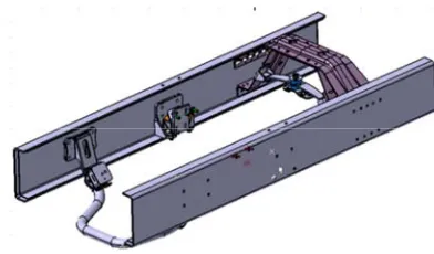
The model structure of this paper is shown in Figure 1. Component structure includes engine front and rear brackets, longitudinal beams, Yuanbao beams and upper and lower parts of three beams. The information of each power assembly is shown in Table 1 and the relevant parameters are shown in Table 2.
Figure 1. Model of powertrain mounting bracket.
Table 1. Material and Thickness of Parts.
Name Material Thickness/(mm)
Longitudinal beam 610L 7.0 Reinforcement plate 510L 4.0 Engine front bracket ZG230-450 Casting Engine rear bracket ZG230-450 Casting
Cross member Q235A 30
Upper part of cross member 09SiVL 6 Lower part of cross member B510L 4
Table 2.Relevant parameters of powertrain.
Name/Unit Amount
Quality of Powertrain/kg 740.05
Centroid coordinates of powertrain/mm (27.49, 4.85, 118.21) Forward maximum output torque/N*m 9672
Reverse maximum output torque/N*m 8736 Front mount rubber stiffness/mm (115, 115, 616) Stiffness of rear mount rubber/mm (680, 210, 590)
The material of engine mounting bracket is ZG230-450, modulus of elasticity is 210 GPa, Poisson's ratio is 0.3, material density is 7.86*103 kg/m3, yield strength is 230 MPa, and tensile strength is 450 MPa.
The CATIA model of powertrain mounting bracket is imported into HyperWorks for grid generation. The finite element model of mounting bracket as shown in Figure 2 is obtained. The total number of model elements is 473179 and the total number of nodes is 151189.
Figure 2. Finite element model of powertrain mounting bracket.
2.2. Strength Performance Analysis
(a)
(b)
24 Lv Lin et al.: Strength Performance Analysis and Improvement of Engine Mounting Bracket for a Commercial Vehicle
(d)
(e)
(g)
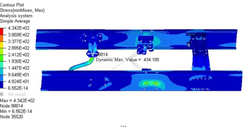
Figure 3. Stress distribution of powertrain mounting.(a)Jolt condition.(b)Braking condition.(c)Turning condition.(d) Forward maximum torsion condition.(e)Reverse maximum torsion condition.(f)Forward maximum torsion impact condition.(g)Reverse maximum torsion impact condition.
From the stress distribution maps of the above seven working conditions, it can be seen that:
(1) Under braking and turning conditions, the maximum stress values are 113.9 MPa and 167.7 MPa, which are far less than the yield strength of 230 MPa. Under reverse maximum torsional impact, the maximum stress value is 434.2 MPa, which is less than 450 MPa of material tensile strength. Therefore, it can be considered that under these three conditions, the strength of the mounting bracket will not appear.
(2) The maximum stress values shown in the diagrams are 257.6 MPa, 258.1 MPa and 238 MPa, respectively, under turbulent, forward and reverse maximum torsion conditions, which are larger than the yield strength of 230 MPa. Under the condition of maximum forward torsional impact, the maximum stress value is 472.8 MPa, which is greater than the tensile strength of the material 450 MPa. Under these four conditions, there is a risk of fracture of engine bracket.
In the stress distribution maps of the above conditions, high stress mostly appears in the front part of the right mounting bracket of the engine. On the basis of the same material technology, the engine mounting bracket is rigidly connected to the left and right frame, but the early cracking of the right mounting bracket is more serious than that of the left mounting bracket (the cracking ratio of the right mounting bracket to the left mounting bracket is 10:1 according to the actual vehicle) [13]. The reason is not only the working condition, but also the side pressure of the engine. Due to the clockwise rotation of engine crankshaft, the lateral pressure on the right mount is several times that on the left, so the right mount bracket is prone to early cracking [14].
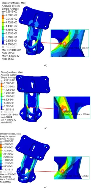
The stress nephogram of front bracket under bump condition, forward maximum torsion condition, reverse maximum torsion condition and forward maximum torsion impact condition is shown in Figure 4.
26 Lv Lin et al.: Strength Performance Analysis and Improvement of Engine Mounting Bracket for a Commercial Vehicle
(b)
(c)
(d)
According to the stress nephogram of Figure 4, the maximum stresses of the front suspension bracket under bump, forward maximum torsion, reverse maximum torsion and forward maximum torsion impact are 238.4 MPa, 238.1 MPa, 258.1 MPa and 472.8 MPa, respectively, which exceed the yield strength and tensile strength of the material. The maximum stress concentrates on the reinforcement step of the part, but the high stress concentrates only on a small part. This is mainly because the sheet metal stamping parts are hard and brittle. Under the alternating stress produced in the working condition, the excessive fillet position of the bracket is prone to stress concentration [15]. This vehicle is a commercial vehicle. Considering that the quality of the rear-loaded goods is larger, the engine loaded goods will move forward and backward due to the pull of the quality of the engine loaded goods. Under the condition of bump and torsion, the engine also moves up and down. The bracket receives the action of tension or pressure, and the stress concentration leads to the eventual breakage.
3. Structural Improvement Analysis
3.1. Structural Improvement Scheme
According to the stress nephogram of engine bracket, the initial design structure of bracket generally has high stress at the longitudinal and central joint of rigid body, which is the weak point of structural design. Especially on the upper and lower sides of the bracket, the maximum stress is easy to appear at the corner of the root of the side plate connected with the engine. Based on the results of simulation analysis, the structure of engine front mounting bracket is improved. On the basis of the initial design scheme, the specific improvement scheme is as follows:
(1)Change the size of weight-reducing hole of fixed plate from 60x25 mm to 70x60 mm;
(2)cancel the step of reinforcing bar to eliminate local stress concentration;
(3)Change the size of fillet on both sides of support from R20 to R39;
(4)Change the size of long round weight-reducing hole on support from 80x25 mm to 90x60 mm. The improvement scheme is shown in Figure 5.
Figure 5. Structure improvement.
3.2. Strength Contrast Analysis
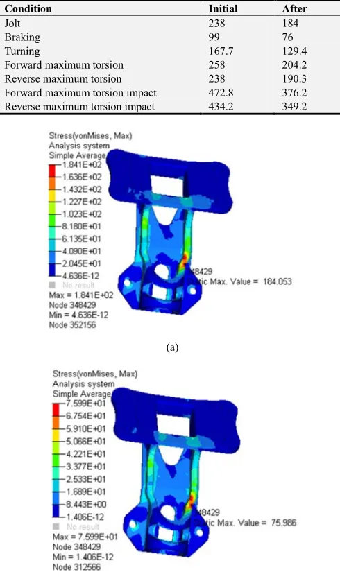
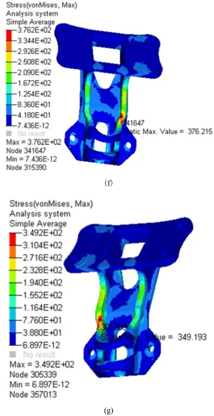
The stress distribution of the improved suspension bracket under the conditions of bump, braking, turning, forward maximum torsion, reverse maximum torsion, forward maximum Torsion Impact and reverse maximum torsion impact is shown in Figure 6. The comparison of maximum stress values before and after improvement is shown in Table 3.
Comparing the stress nephogram of the bracket before and after the improvement, it can be seen that the thermal power of the high stress value area under the improved conditions is more dispersed than that of the initial structure. The maximum stress value is centered on the minimum part before the improvement, which presents a diffusion phenomenon. To a certain extent, the stress concentration phenomenon is improved, and the maximum stress value under each condition is obviously reduced compared with that before the improvement, so as to meet the requirements of the material. Yield strength and tensile strength requirements of materials.
Table 3. Maximum stress before and after optimization/MPa.
Condition Initial After
Jolt 238 184
Braking 99 76
Turning 167.7 129.4
Forward maximum torsion 258 204.2 Reverse maximum torsion 238 190.3 Forward maximum torsion impact 472.8 376.2 Reverse maximum torsion impact 434.2 349.2
(a)
28 Lv Lin et al.: Strength Performance Analysis and Improvement of Engine Mounting Bracket for a Commercial Vehicle
(c)
(d)
(e)
(f)
(g)
Figure 6. Stress nephogram of improved engine bracket. (a) Jolt condition. (b) Braking condition. (c) Turning condition. (d) Forward maximum torsion condition. (e) Reverse maximum torsion condition. (f) Forward maximum torsion impact condition. (g) Reverse maximum torsion impact condition.
The maximum stress of the improved engine mounting bracket under various working conditions has been significantly improved, and the improvement ratio is about 20%, which effectively reduces the stress concentration phenomenon. The weight of the front bracket is 4.173 kg and the optimized weight is 3.842 kg. The quality of the engine bracket is reduced by 7.9%. It shows that the optimization scheme is feasible and can improve the fracture resistance of engine mounting bracket, meet the strength performance requirements, and achieve the goal of lightweight.
4. Conclusion
endlessly, but many reliability technologies can not be successfully applied in the process of engine design; many reliability theories and models are unfamiliar to engineers and are not easily accepted, and can not play a good effect, making the reliability work in design a "decoration". The existing design analysis usually adopts the safety factor method based on engineering experience for deterministic design, which may lead to its lack of reliability or too conservative. In order to obtain the reasonable distribution of engine mounting bracket materials, it is necessary to optimize the original structure. Reliability design needs to analyze the structural reliability. The actual design parameters are almost random variables. It is obviously unreasonable to use deterministic analysis method for structural analysis and design. Based on reliability theory and traditional safety factor method, how to improve the design level of engine mounting bracket, realize the optimization design of structure, reduce the weight of structure, and establish a reliable technology of structural optimization design is the main content of this paper. Through the research, the following conclusions are drawn:
(1) The finite element model of engine mount is established, and the strength analysis is carried out under seven typical working conditions of jolt, braking, turning, forward maximum torsion, reverse maximum torsion, forward maximum torsion impact and reverse maximum torsion impact. It is found that the weak part of the structure is the step of reinforcing bars, and reasonable structural improvement is made to the weak part of the mechanical properties of the bracket in order to eliminate the phenomenon of stress concentration.
(2) According to the requirements of process design, four structural design improvements have been made to the engine bracket. The strength of the improved engine bracket increases by about 20% under various working conditions, and the quality of the engine bracket decreases by 7.9%. At the same time, it achieves lightweight components and effectively improves its strength, which provides a basis for the design and development of engine mounting bracket. Strength optimization design of engine brackets for commercial vehicles.
Acknowledgements
This paper was completed under the kindly care and careful guidance of my instructor. From software learning to simulation analysis, Mr. Wang has always patiently guided me step by step. With the help of the teacher, I did not lose my direction in the design and successfully completed it. Professor Wang's rigorous attitude towards scientific research and his spirit of pursuing excellence are all what I need to learn. Thank you for your help.
Thank my roommates and classmates who fought with me, especially my classmates for their help, and my elders for their help and design parameters. I sincerely wish you all the best in your future work.
Thank you all for taking the time to guide my paper.
References
[1] Pang Jian, Jian Gang, He Hua. Automobile Noise and Vibration [M]. Beijing University of Technology Press, 2006.
[2] Lin Rui, Kuang Bing, Zhou Feng, Li Dexie, Shi Yunpeng. Performance Optimization of Engine Support Based on Variable Density Method [J]. Combination machine tools and automatic processing technology, 2018 (11): 123-126.
[3] Li Xin. Study on Fretting Fatigue Damage Mechanism of Fastener Surface under Characteristic Load of Internal Combustion Engine [D]. 2015.
[4] Murali M. R. A methodology of using topology optimization in finite element stress analysis to reduce weight of a structure [J]. SAE Paper, 2001-01-275 Hu Rongrong, Yang Chen, Yuan Shuang, etc. Finite Element Analysis for an Engine Mounting Bracket [J]. Modern manufacturing technology and equipment, 2015 (2): 1-2.
[5] Bai Kunhai. Strength Analysis of Engine Mounting Bracket [J]. Science and Technology and Engineering, 2012, 12 (32): 8793-8797.
[6] Zhao Lijie, Zhou Zheng, Huang Jianyun et al. Performance calculation and structure design for vehicle powertrain mounting bracket [J]. Journal of Shenyang University of Aeronautics and Astronautics, 2016, 33 (3): 38-46.
[7] H A Eschenauer, N Olhoff. Topology optimization of continuum structures: a review [J]. Applied Mechanics Review, 2001, 54(4): 331-389.
[8] J Park, J Hwang, J Kim. Engine Mounting System Stiffness Optimises Handling and NVH Performance [J]. Atz Worldwide, 2016, 118(1): 36-41.
[9] LE Ooi, ZM Ringin. Optimization of an engine mounting system with consideration of frequency-dependend stiffness and loss factor [J]. Journal of vibration and control, 9(2014): 162-168.
[10] Li Jiankang, Zheng Lihui, Song Xianglong. Modal analysis of dynamic stiffness of automotive engine mounting system [J]. Automotive Engineering, 2010, 31 (5): 457-461.
[11] Hu Jin-fang, Rajendra Singh. Improved torque roll axis decouping axiom for a powertrain mounting system in the presence of a compliant base [J]. Journal of sound and vibration, 331(2012):1498-1518.
[12] Guo Shaoliang, Li Jinchao, Xiong Fei et al. A Research on Structure Optimization of Engine Mount Bracket Based on Misuse Working Condition [J]. Automotive Engineering, 2016, 38 (10): 1220-1226.
[13] Zhu Hongjun, Cheng Rui. Development of Die Casting Parts for Engine Suspension Bracket [J]. Special Casting and Non-ferrous Alloys, 2019, 39(01): 35-37.
[14] Cao Huawei, Li Eryong, Wang Jian. Reasons for Fracture of Automotive Engine Bracket [J]. Automotive Technology and Materials, 2015 (07): 45-49.