Volume-7 Issue-1
International Journal of Intellectual Advancements
and Research in Engineering Computations
Measurement and control of level using load cell in de-inking process
Pratheep.D
1, Santhosh.R
1, Tamilarasan.R
1, Ganesh.RM
2 1UG Scholar, Department of Electronics and Instrumentation Engineering,
Nandha Engineering College, Erode
2
Associate Professor, Department of Electronics and Instrumentation Engineering,
Nandha Engineering College, Erode
ABSTRACT
De-inking process is the one in which the ink from the office waste and news -papers are removed in order to prevent it from dispersing into the pulp. Sodium soap is used for removing the ink. This sodium soap is processed in a container. The existing method has level controllers for controlling the level. But our proposed method has “load cell” for measuring and controlling the level. In this method the level is measured by measuring the weight of the sodium soap inside the container. Pulp is a cellular fiber which is made from wood/Bagasse. The Paper is being made with different kinds of Pulp. Bagasse is the main raw softwood, Hardwood, Chemical, Mechanical and Imported Pulp are mixed with some prop ortionate ratio to produce different varieties of Papers like Cream wove, Copier, Radiant, Maplitho and etc material for making Paper
INTRODUCTION
Recycling is an old tradition of the paper industry. The first papers were manufactured from old rags, and recovered papers have always been a source of fibres for the paper industry. Nowadays, out of the nearly 370 Millions tons paper and board produced worldwide, more or less half of them are but since 15-20 years there is a drastic increase of the use of recovered papers to produce, through deinking, white grades such as newsprint, tissue, market pulp and also more recently magazine papers (SC&LWC)…Deinking is indeed a sophisticated way of recycling, high grade papers can be produced by using this technique. By using the dinking technology, where grade papers can be produced from post-consumer or post-industrial recovered papers. This means that the components which cause a reduction of brightness- the inks- must be removed, but also that the additives are contaminants. They include various grades of adhesives (such as binding materials, labels, tapes), staples, plastic firms, links, varnishes, and
all the components of the pulp which cannot e used to produce paper. In some cases fillers must also be removed. Recycling means manufacturing using recovered papers as the raw materials; two main steps have to be performed: Production of a (recycled) pulp, from recovered papers Manufacturing a paper by using this pulp alone or mixed with other pulps (virgin or recycled).This second step is, in principle, not very different of the production of paper from virgin pulp but this is not the case for the first one. The production of deinked pulp is indeed carried out using techniques totally different than those used for the production of pulp from wood. The recycling technology is the combination of the various treatments carried out to produce a pulp from recovered papers and to clean it for its use on a paper machine to produce paper. The deinking technology includes all the main steps of the recycling technology, but special treatments are added I order to remove the ink.
STEPS OF DE-INKING PROCESS
Recycling
Pulping is always the first step. During pulping, fibres are separated and all the additives added to the paper during the printing and converting process are (or should be) separated from the fibers. Various kinds of devices can be used: low consistency pulp, medium consistency pulpers and dues are proposed by machinery suppliers. The choice of the type of pulper has to be made by considering various parameters including the efficiency of defibering and energy consumption ut mainly with respect to: Defibering kinetic Minimising the breaking up of contaminants in order to improve their removal efficiency. Due to these requirements deflakers are no longer in use in deinking plants. Efficient ink detachment(however this objective is sometime contradictory with the previous one).Chemicals (caustic soda, sodium delicate and soap) are most often used in the pulping stages in order to improve ink release from the fibers even if there is a recent trend to move to neutral
repulping conditions. Beaching chemicals (hydrogen peroxide) are also often used in this stage. Several studies dealing specifically with this unit operation have been done recently (Fabry el al.1999i, Fabry and carre 2002ii & 2004iii , Fabry et al. 2005iv, Bennington and Wang 1990v, Ben and Dorris 1990vi, detailed bibliography in Fabry 2007vii). [1-5]
REMOVAL OF CONTAMINANTS
The removal of contaminants is based on their different properties, compared with fibres, dines and fillers:
Differences in size: Particles smaller than fibres can be removed by washing and contaminants larger than fibres, if stiff enough, can be removed by screening.
Differences in density: If sufficiently large, particles having a density other than 1 can be removed by centrifugal cleaning. Some cleaners are designed to remove high density (>1) contaminants and other to remove lightweight contaminants (density<1).
Difference in surface properties: Floation can remove hydrophobic particles, additives (synthetic surfactants or soaps) are generally used to collect
Results presented by McCool in 1987viii (Figure 1) show that each technique is efficient for the removal of contaminants in a defined size range.
This figure can be considered as a good approach to washing and screening efficiency, and some machinery suppliers reger to it to characterize the improvement in efficiency of new devices (Backman et al.1993ix)
For cleaning efficiency, the combination of size and density must also be considered and floation efficiency depends mainly on surface properties.
Screening
Screening consists in removing contaminants by keeping them on a screen while fibres go through the openings (slots or holes) of the screen.
At the beginning, the screening devices were open vibrating screens, today the screens are closed and pressurized to increase capacity. Screening can remove large & stiff contaminants including plastic films, wet strength papers
Cleaning
Cleaning is based on particle separation in a centrifugal flow field. A swirling motion is created by the tangential inlet flow. The vortex motion creates centrifugal forces which causes the particles heavier than the stock to migrate to the outside of the cleaner, while lightweight particles migrate toward the vortex core.
Large size cleaners are generally used on high consistency (5%) pulp, while small cleaners can be designed to remove heavy or lightweight contaminants.
Cleaning (heavy contaminants) can remove metals, sand and some varnish particles. This technique has also been proposed to remove toner ink after agglomeration with appropriate chemicals (Olson et al 1992x).
s
Flotation
Flotation consists in removing hydrophobic particles (particularly ink particles), by flotation them up to the surface with air bubbles. Flotation aids are used to improve the attachment of ink particles to air bubbles.
The first deinking cells were similar to those used in the mining industry. Nowadays, various devices designed by machinery suppliers are proposed in order to improve air mixing and foam removal. Flotation can remove ink (oil based ink with hydrophobic characteristics), varnishes and some adhesive particles.
Washing
Washing consists in removing small particles with water through a screen, large particles including fibres being retained on the screen. The washing process always corresponds to that of a thickening stage and is derived from the same technology. Various types of devices, operating at
various consistencies, with different efficiencies, can be used.
Dissolved air flotation
A process water treatment by dissolved air flotation can be implemented in order to remove fillers and inks from washing waters and small colloidally dispersed contaminants in thickening waters.
EXISTING METHOD
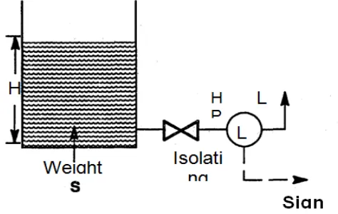
Level transmitter
The level in the tank affects not only the quantity delivered but also the pressure and rate of flow in and out of the container. The substance to be measured can be inside a container or can be in its natural form. The level measurement can be either continuous or point values. Continuous level sensors measure the level to determine the exact amount of substance in a continuous manner. Point-level sensors indicate whether the substance is above or below the sensing point. This is essential to avoid overflow or emptying of tanks and to protect pumps from dry run.
Level transmitter is used to measure the level of the tank, and convert into 4-20mA signal that is accepted by the PLC. The level transmitter is mounted in the bottom of tank as shown in the figure. The level in the tank is calculated by finding the differential pressure in the tank
P=P1-P2
P1=Total Pressure in the tank ,P2=Atmospheric Pressure
By knowing the density of the liquid, level (height) of the tank is found out
H=P/g
where, H - height of the liquid level in the tank.
p – Differential pressure and - Density of the liquid.
The most commonly used level transmitter in industries is the differential pressure (DP) based capacitive type. Capacitive level transducer is an example of indirect measurement of level. They are used for wide variety of solids, aqueous and organic liquids, and slurries.
Figure 5: Level transmitter
The principle of differential pressure (DP) based capacitive level measurement is based on change of capacitance present in the diaphragm of DP sensor. The capacitance depends on the fluid level. An empty tank has a lower capacitance which is the atmosphere pressure is 1bar.
The higher capacitance is calculated by adding the atmosphere pressure with the height of tank is then multiplied with density of liquid present in tank.
The dielectric medium present in the differential pressure sensor is silicon oil. The value of C depends on dielectric used, area of the plate and also distance between the plates.
where,
C = capacitance in picofarads (pF)
K = relative dielectric constant of the insulating material
A = effective area of the conductors
d = distance between the conductors
This change in capacitance can be measured using AC Bridge. The measurement is made by applying an RF signal between the conductive probe and the vessel wall. The RF signal results in a very low current flow through the dielectric process material in the tank from the probe to the
vessel wall. When the level in the tank drops. The dielectric constant drops causing a drop in the capacitance reading and a minute drop in current flow. This change is detected by the level switch's internal circuitry and translated into a change in the relay state of the level switch in case of point level detection. In the case of continuous level detectors, the output is not a relay state, but a scaled analog signal.
PROPOSED SYSTEM
Two inputs sodium soap and water are added in the ratio of 1:3. The soap is fed from the container and water is fuelled from the pump. The load is connected at the bottom of the tank which is interfaced with the microcontroller. Initially the load cell is calibrated to null. The process beings when the tank is empty and then the valvel connected to the soap container is opened. When one kg of soap is added to the tank, the load cell detects the changes in the tank and microcontroller automatically closes the valvel. The valve2 is opened 3kg of water is pumped into the tank when the valvel is closed. The tank weights total of 4 kg the pump is closed. The mixture gets heated by the element and the temperature inside the tank is maintained at 630C. The temperature inside the tank is continuously monitored by using RTD sensor. The mixture gets stirred by using the agitator which is connected to the stepper motor. The speed of the motor is maintained at 25RPM.
The agitator is stirred for the time delay of 15 minutes.
When the process is completed the valve2 is opened. The mixture in the tank is drained into the storage tank. The valve2 gets closed, the process is repeated. The power supply is given to the controller from the voltage regulator of 5V. The LCD which is interfaced with the controller displays the level of the mixture in the tank, the opening and the closing of valves and the temperature inside the tank.
CONTROL TECHNIQUE
NA – Soap preparation
Main Process (Soap mixing)
Controller checking
valve between mixer and storage tank is opened by the action of microcontroller .
Process
The process starts. The water flow starts. When the water flowing sequence is finished, the heating sequence starts and the stirring starts. When the heating is finished, the powder dosing process starts. When the powder dosing sequence is finished the stirring process starts at 25 rpm. When the level product is under the stirring level set point the stirring stops. When the stirring process is finished, the discharge process starts.
Filling Tank
Controller checking
The operator must check. The quantity of product in the tank.
Process
If the product level is under the low level. The operator first fills the water .The valve between the mixer tank and the water tank is opened. If the needed amount of water is added, the valve is closed by microcontroller action. The level of the water is weighed by load cell.
Powder dosing
Controller checking
The operator must check the tank contains product.
Process
The valve between the mixer and the soap tank is opened. If the certain amount of soap is added, the valve is closed by the controller action. When the soap dosing process is completed, the stirring process starts. The stirrer rotates at the speed of 25 rpm. When the actual level is under the stirring level .The motor stirring stops. When the stirring process is completed the discharge process starts.
Discharge to tank
Controller checking
The operator must check. The product level is under the set-point call level in the tank .The soap tank valve and the water tank valve is closed. The storage tank valve is opened
Process
The discharge process starts .The discharge valves open. The weight in the mixer tank is decreasing. When the low level is reached in the draining mixer tank. If the storage tank is fully filled, the discharge valve is closed by the controller action and the whole process is repeated continuously.
Advantages
Using non contact type load cell makes it free from abrasion
Corrosion resistant
Accurate in measurements
Coating of sodium soap over the sensor is eliminated
Density changes does not affect the measurements
Long lasting and requires no maintenance after installation
RESULT AND CONCLUSION
The mixture is prepared with the correct proportion as mentioned in the program .The main advantage is that the coating of soap over the sensor is eliminated completely. It is free from abrasion and corrosion resistant. According to that the correct proportions will be mixed at correct time by their timer functions. The weight ratio is maintained accurately by the load cell. The change in the density does not cause any changes in measurement. It requires no maintenance once it is installed. So, it is beneficial to use in paper industry.
REFERENCES
[1]. Jacob L. Johansen, ARC Centre of Excellence for Coral Reef Studies, and School of Marine and Tropical Biology, James Cook University, Townsville, Queensland, Australia.
[2]. Muller, R. M. de Brito and R. J. Bender "Instrumented Sphere for Compression Analysis", Proc. IEEE IIMTC 2008.
[3]. M. Niraimathi, S.Sivakumar, R.Vigneshwaran, R.Vinothkumar, P.Babu.[1]U G Students, Department of ECE, K. S. Rangasamy College of Technology, Tiruchengode, Tamilnadu, India. Associate Professor, Department of ECE, K. S. Rangasamy College of Technology, Tiruchengode, Tamilnadu, India. Published in "International Journal of Electronics and Computer Science Engineering".
[4]. J.G. Rocha, C. Couto, J.H. Correia. Department of Industrial Electronics, UniÍersity of Minho, Campus de Azurem, 4800 Guimaraes, Portugal Received 14 September 1999; received in revised form 8, 2000; accepted 9, 2000.