The Effect Of Thickness On Some Physical
Properties Of Cdse Thin Films
Sameer A . Maki, Bushra K . Hasson, Tahir H . Mahmoud
Physics department, collage of education for pure science, ibn Al-Haitham , university of Baghdad, Baghdad, Iraq .
Corresponding author, E-mail: [email protected] Abstract—In the present paper, cadmium
selenide (𝐜𝐝𝟎.𝟓𝐬𝐞𝟎.𝟓) Thin films were fabricated on
to well cleaned glass substrates by thermal evaporation under vacuum method with optimized deposition parameters at a various thickness, the as-deposited films
are subjected to various microscope studies such as SEM and AFM , and the results were reported in this research, the hall effect measurements show that CdSe films exhibit n-type semiconductor and its resistivity decreased by increasing thickness .
Keywords— Cadmium Selenide, Thermal Evaporation, AFM, SEM, Electrical Properties.
1. INTRODUCTION
Cadmium selenide matter is the one of II-VI group compound that which belonging to the chalcogenide glassy semiconductors , which has been attracting considerable attention during the last few decades due to his wide application in various optoe-lectronic technologies such as lasers [1] , sensors [2], photo electrodes[3], light emitting diodes[4], and solar cells [5].Cadmium selenide has played a prominent part in the modern material science and technology it is a good photovoltaic material because it has high absorption coefficient and has optimum band gap energy ( 1.74eV ) nearly to the efficient absorption of light and conversion in to electrical energy , it is one of the most promising n-type semiconductor materials and it has cubic zine blende and hexagonal wurtzite structures [6,7] .CdSe thin film can be deposited either by
physical or by chemical technique, in this research we are used thermal evaporation technique which based on evaporation the material by thermal energy and allowing the vapor steam to condense on the substrate to formation a continuous film.This procedure will done under high vacuum in order to grow uniform and homogeneous thin film and to avoid production oxide layers as well as impurities [8] , for all this, we chosen this technique as well as consider the most promising physical techniques . in the present paper, we report the fabrication of ( Cd0.5 Se0.5) thin film on glass substrates by physical vapor deposition Technique to study their morphological and electrical properties in order to reach the optimum condition to fabricating the best heterojunction in the future .
2. EXPERIMENTAL PROCEDURE
Alloy of (Cd0.5 Se0.5 ) were prepared by slow cooling of the molten technique , the exact proportions of high purity ( 99.99 % ) Cd
sealed in evacuated (10−5torr ) the quartz
ampoule ( length 25cm
And, the internal diameter 1cm). The ampule containing material was heated to 1200C° and was held at that temperature for 1hour, the temperature of the furnace was raised slowly at a rate of 5C° / minute, during heating the employee was constantly rocked by rotating a ceramic rod to which the employee was tucked away in the furnace, this was done to obtain homogeneous alloy .
After rocking for about 1hour, the obtained melt was slowly cooled in the furnace until the furnace temperature rose to the room temperature , after that , the sample was then
taken out by breaking the quartz ampoule.( Cd0.5 Se0.5 ) films were evaporated on to well cleaned glass substrates by thermal evaporation under vacuum technique using coating unit Edward type E(306A), the evaporation process was carried out at room substrate temperature ( 27C° ) and at a base pressure of ( 10−5torr ) using molybdenum boat . After CdSe films coated, some of these samples were subjected to a various microscopic studies such as SEM and AFM , and the other samples were coated by evaporating on aluminum to make front ohmic contact electrodes in order to prepare this film to hall measurement .
3. RESULTS AND DISCUSSION
3.1. XRD ANALYSIS
The shape and type of the lattice structure of thermally evaporated CdSe thin films were carried out by x-ray diffraction technique and the patterns of the films with a various thickness ( 300,500,700, and 900nm ) are shown in fig.1, this pattern revel that all prepared ( Cd0.5 Se0.5 ) films as a different thickness are polycrystalline in nature and have stable hexagonal type structure with atomic growth in three crystal orientation (002),(102) and (103) which belonging to the hexagonal phase at diffraction angle (20 = 25.3538 ),(20 = 35.1072 ) and (20 = 45.7884 ) respectively, and with preferred orientation along (002) plane for all prepared films. this result was found well agreed with the standard ASTM data file (08-0459) and
Figure.1: X-ray diffraction patterns of CdSe thin films at various thicknesses: (a)300 nm,(b)500nm,(c)700nm and (d)900nm
3.2. AFM ANALYSIS
The surface morphology of ( Cdo.5 Se0.5)
thin film that prepared as a different thickness was studies by atomic force microscopy, figure (2) (a)-(d) show the (3-D) images and the distribution chart of ( Cd0.5 Se0.5 ) Films as- deposited at a various thickness , AFM images prove that the grains are uniformly distributed within the scanning area ( 2500nm x 2500nm ) with individual columnar grains extending up words .It was observed from AFM studies that average grain size on the surface of ( Cd0.5
Se0.5 ) film increased when increasing thickness, it can be attributed to the increased agglomeration of particles on the surface of the
prepared thin film when increasing thickness , this indicates the improvement of crystallinity of the films during increasing thickness . Also from AFM images, it is clearly that the film is uniform and the surface of substrate is well covered by these particles. The roughness of the films were also measured by (AFM), we observed a strong dependence of the roughness on the film thickness and have a high value (7.54nm) at a large prepared thickness (900 nm). the estimated values of root mean square (RMS) of surface and average roughness and Average grain size are listed in Table (1).
Table.1: Grain Size, Roughness and Root mean square of CdSe films of various thickness
Thickness (nm)
Grain Size (nm)
Root mean square (nm)
Roughness density (nm)
300 78. 80 0.25 0.198
500 80.94 1.16 0.979
700 97.73 1.42 1.18
Figure.2: (3-D) AFM images and Distribution chart of CdSe thin films of various thickness
3.3.SEM ANALYSIS
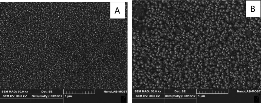
In our research we are studying the
thickness (300nm) consist of dense layers of small nanoparticles ( Cd0.5 Se0.5 ) Which are distributed in uniform and close substrate region and have spherical shape, while when increasing thickness of the film until two (900 nm) these nanoparticles had been converted in to bigger clusters (large grains) with a large diameter as shown in fig.2 (b) This is due to the fusion a large number of ( Cd0.5 Se0.5) Nanoparticles that which gathered and stacked when
increasing thickness. From that and when we are comparing between the two different sample's thickness, we deduced that the morphology uniformity of the sample (b) ( i.e. 900nm ) is better in the photovoltaic applications than that of the sample (a) (i.e. 300nm), The result of this study Corresponding to the increasing crystallinity when increasing thickness and compatible with the AFM and XRD results.
Figure.3: SEM of CdSe thin films of a various thickness: (a) 300 NM and (b) 900 NM
3.4. Hall Effect measurement
In the present work, the electrical parameters such as: carrier concentration, Hall coefficient Hall mobility, resistivity and conductivity of prepared Cd0.5 Se0.5 films were carried out at room temperature by using Ecopia Hall Effect Measurement System ( HMS-3000 ) and the results of this measurement are listed in table 2. The negative sign in front of hall coefficient value, shown that all prepared films
have a negative type conductivity and this is consistent with the previous research [11, 12] . The data also shown that the conductivity of prepared films was increased with increasing thickness, while in the same time, the resistivity has been decreased , so that we can benefit from the films of this matter at the largest thickness prepared in our current research in the photovoltaic application successfully.
Table 2: Electrical parameters and type conductivity of CdSe films as different thickness
Thickness (nm)
Carrier Concentration/ cmᶟ
Mobility (µ)
cm² / V.sec Resistivity (ρ) Ω.cm Conductivity (σ) 1/(Ω.cm)
300 3.907E+12 5.185E+0 30.85E+4 3.24125E-06 500 1.761E+12 1.494E+1 23.76E+4 4.20949E-06 700 2.319E+11 1.499E+2 17.98E+4 5.56189E-06 900 2.348E+10 1.713E+3 15.54E+4 6.4354E-06
CONCLUSION
1. The x-ray diffraction analysis showed that the nature of the crystal structure of pure cadmium selenide thin films which deposited by thermal evaporation technique and prepared as a different thickness was improved by increasing the thickness from poly crystalline as in the films ( 300nm ) to the single crystalline as in the films ( 500,700, and 900nm ) and with a clear increase in the intensity of preferred peak (002) with increasing thickness.
2. The result of atomic force microscopy (AFM ) showed that there are clearly increasing in the average grain size by increasing thickness, especially in thickness (900 nm ) with a maximum value (99.24NM) which indicates to get on a nanoscale structure.
3. The atomic force microscopy results have also been shown that the surface
roughness of prepared thin films increasing with thickness until to reach to the maximum value (7.54NM) at a thickness (900nm) which indicates improved in the crystalline structure and a reduction in the grain boundaries with thickness, this is well agreed with XRD results.
4. The results of the scanning electron microscope showed that the deposited nanoparticles were transformed by increasing thickness in to large grains and with a larger diameter indicating improved crystallization by increasing thickness.
5. The results of Hall effect measurement showed n-type semiconducting nature of prepared films, and the resistivity of the films was decreases by increases thickness.
References
[1]. J. g. Hernandez, J. H. Borja, R .R. Bon, M .C .Sanchez, Y. V. Vorbier, ʺ x-ray and optical properties of CdSe thin films,ʺ Mater.Chem.Phys.113(2009) 824-828 .
[2]. S. J. Chang, F. S. Juang, H. P. Liu, I. J. Chen, A.K.Bhatnagar, ʺCharacterization of cu-doped CdSe thin films grown by vacuum evaporation ,ʺ J.Cryst.Growth 224 (2001) 74-82.
[3]. R. N. Donald, B. E. Arthur, J. W. Edmund, F.G.John, ʺ Detection of ammonia and phosphine gases by reversible modulation of cadmium selenide photo luminescence intensity,ʺ J.Cryst.Growth 148(199) 63-69 . [4]. K. M. Garadkar, P. R. Bhagat, V. M. Bhuse,
P.P.Hankare, S.D.Delekar, ʺ CdHgSe thin films: preparation, characterization and
optoelectronic studies, ʺ
Semicond.Sci.Tech.19(2004) 277-284.
[5]. B.Holmstrom, T.Gruszecki, ʺPreparation of
energy conversion,ʺ Sol.Energy Mater.Sol.Cells 31(1993) 227-234.
[6]. D. C. Trivedi, K. R. Murali, and V. Swaminathan , ʺ Characteristics of monocrystalline CdSe films ,ʺ Sol.Energy Mater.Sol.Cells 81(1), (2004) 113-118.
[7]. K. Tanaka, ʺ Structural Phase Transitions in Chalcogenide Glasses ʺ Phys. Rev. B, 39 (1989)1270-1279.
[8]. M. S. Dhaka, S. P. Nehra, A. Purohit and S. Chander, ʺ Thickness Dependent Physical properties of thermally evaporated nanocrystalline CdSe thin films, ʺ acta Metallurgica Sinica (English letters), 28(10), (2015) 1299-1304.
CdSe Thin Films Deposited by Spray Pyrolysis, ʺ Mater.Ghem.Phys.121(2010)53-57.
[11]. W. Ching and Y. N. Xu, ʺ Electronic, Optical and Structural properties of some wurtzite crystals ʺ, Physical Review B, 48(7)(1993)4335-4351.
[12]. V. S. Kumar and C. C. Bijumon , ʺ Raman, PL and Hall effect Studies of CdSe Thin Film Deposited by Chemical Bath Deposition ʺ, International Journal of Scientific and Technology Research ,5(5)2016.