Abstract—A tracking system that has redundant
sensors can accommodate a faulty sensor. The main purpose of a tracking system is to lock in the target. Having redundant sensors give a chance to the system to lock in when one of the sensors is faulty. Mathematical relations between the signals lead to identification of the faulty sensor and automatic reconfiguration of the system.
Index Terms—Algorithm, detection and diagnostic, fault-tolerant control, fault detection and identification.
I. INTRODUCTION
The sensors could be light sensors as shown in Fig. 1. The system is a platform fitted with four sensors. When a sensor becomes faulty, the position of the frame and of the light source may differ and a searching process must be initiated.
If the frame is rotated 90 degrees to the right, the source of light would be in S1, and then rotate to the left until is 90 degrees from the horizontal and the source of light is in S7. During this process the source of light would be passing in order all sectors S1 to S7. If no sensor is faulty the signals LL, LH, H, L, RHand RLsuffer only one transaction from 1 to 0 at different time intervals. When one sensor is faulty three signals are wrong and three are correct.
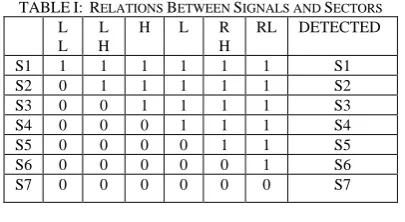
Four no fault the signals should exhibit the transitions shown in Table I.
There are a lot of proposals to design solar tracking systems [1], [2].
The orientation requires a spatial tracking system having two perpendicular directions. A practical approach is described in [3].
TABLE I: RELATIONS BETWEEN SIGNALS AND SECTORS
L L
L H
H L R H
RL DETECTED
S1 1 1 1 1 1 1 S1 S2 0 1 1 1 1 1 S2 S3 0 0 1 1 1 1 S3 S4 0 0 0 1 1 1 S4 S5 0 0 0 0 1 1 S5 S6 0 0 0 0 0 1 S6 S7 0 0 0 0 0 0 S7
A faulty signals creates one of the following behaviors Transition from 1 to 0 doesn’t follow the sequence LL,
LH, H, L, RH, RL.
Manuscript received Novemer 2, 2012; revised December 25, 2012. This work was supported in part by the Australian College of Kuwait
The authors are with Royal Melbourne Institute of Technology, Melbourne, Australia (e-mail: [email protected], [email protected], [email protected]).
No transactions occur.
A transition from 0 to 1 is detected.
The control system tries to keep the frame inS4 (000111). The two signals used to keep the target in S4 are X and Y. When is no fault X=Hand Y=L. In equilibriumX=0 and Y=1.
Fig. 1. The sensors location
II. FAULT DETECTION
The target moves from S4 either in S3 or inS5. Either way, there is only one signal that changes its value when target moves in S3 or S5. If the change is 1 to 0, then the target moves to higher sectors and to the lower sectors if the changes are from 0 to 1.
All signals are monitored in order to detect the fault. All signals to the left of Xare 0 and all signals to the right ofY are 1. When X=0 and Y=1 and any signal to the left is 1 or a signal to the right is 0, a fault is detected.
III. FAULT IDENTIFICATION
A reasonable assumption is that when the target moves from left to right, the only signals having only one transition from 1 to 0 are the signals not distorted by a faulty sensor, when the target moves from left to right. The fault identification is given by a fault matrix F.
Consider that there are kconsecutive readings. A reading matrixRis created as follows:
1 1 1 1 1 1
2 2 2 2 2 2
k
k k k k k
ll lh h l rh rl
ll lh h l rh rl
R =
ll lh h l rh rl
(1)
A column represents the readings of one signal. The above matrix is assumed that only one reading is taken for each sector or it may happen that for practical considerations more readings are taken for the same sectors.
Fault Tolerant Traking Control System
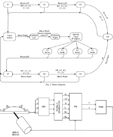
Fig. 2. States diagram
Fig. 3. System control block diagram
An R matrix for 9 readings could look like the following example:
1 1 1 1 1 1
0 1 1 1 1 1 0 0 1 1 1 1 0 0 0 1 1 1
0 0 0 0 1 1 0 0 0 0 0 1
0 0 0 0 0 0 0 0 0 0 0 0
0 0 0 0 0 0 0 0 0 0 0 0
R =
(2)
It can be proven that the matrix F=RTR is size 66, independent of the number of readings.
The elements of the first raw must be all ones and the elements of last rows must be zeros.
A faulty signal will have a 0 to 1 transition, looking at the column from top to bottom.
Create matrixF=RTR.
The fault matrixFis
2
1 1 1 1 1
2
1 1 1 1 1
2
1 1 1 1 1
1
k k k k k
i i i i i i i i i
i i i i i
k k k k k
i i i i i i i i i
i i i i i
k k k k k
i i i i i i i i i
i i i i i
k i i i
F =
ll lh ll h ll h ll rh ll
ll lh lh h lh l lh rh lh
ll h lh h h l h rh lh
ll l
1
2
1 1 1 1
2
1 1 i=1 1 1
1 1 1 1 1
i
k i i i
k k k k
i i i i i i i
i i i i
k k k k k
i i i i i i i i i
i i i i
k k k k k
i i i i i i i i
i i i i i
rl ll
lh l h l l rh rl
ll rl lh rl h rl l rl rh
ll rh lh rh h rh rlh rh rh
1
1
1
1 2 1 k
i i i k
i i i k
i i i k
i i i k
i i
rl lh
rl lh
rl l
rl rh
rl
(3)
The matrix is symmetric. The elements are the result of scalar product of two vectors.
For example:
H
h h h h h h
12 3 4 5 6
When signals are not corrupted:
1) Columns start with 1s followed by 0s after threshold. 2) Any column on the left has at least one extra 1.
1 1 1 1 1 1
2 2 2 2 2 2
3 3 3 3 3 3
1 2 3 4
1 2 3 4 5 6
1 2 3 4 5 6
n n n n n n
n
n n
n
n
n
n n n n n n
F
n n n n
n n
n n n n
n n
n n n n
n n
(4)As the result if the 1s in LL are
n
1, in LH aren
2, in Hare3
n
, inLaren
4, in RLaren
5 and in RHaren
6 the matrix F becomes:where:
n
1<n
2<n
3<n
4<n
5<n
6.In this example when no fault is present:
n
1=1,n
2=2,3
n
=3,n
4=4,n
5=5 andn
6=6.A very important observation that matrix Fhas the same value, independent of the direction the target is moving. It is assumed that only one sensor could be faulty.
There are four possible cases:
1) A1 faulty. The vectors H, RHand RLare not corrupted. 2) C1 faulty. The vectors LL, LHand Hare not corrupted. 3) A2 faulty. The vectors LH, Land RLare not corrupted. 4) C2 faulty. The vectors LL, Land RHare not corrupted.
IV. ALGORITHM
Because F matrix is symmetric, the elements above the diagonal can be ignored.
LL LL
LL LH LH LH
LL H LH H H H
F
LL L LH L H L L L
LL RH LH RH H RH L RH RH RH
LL RL LH RL H RL L RL RH RL RL RL
(5)
The matrix Ffor the four possible faults is: A1 faulty. Vectors H, RHand RLare not corrupted.
3
3 5
3 5 6
LL LL
LL LH LH LH
LL H LH H n
F
LL L LH L H L L L
LL RH LH RH n L RH n
LL RL LH RL n L RL n n
(6)
C1 faulty. Vectors LL, LHand Hare not corrupted.
1
1 2
2 3 1 n n n
LL H n n
F
LL L LH L H L L L
LL RH LH RH H RH L RH RH RH
n LH RL H RH L RL RH RL RL RL
(7)
A2 faulty. VectorsLH, Land RLare not corrupted.
2
2 4
2 4 6
LL LL
LL LH n
LL H LH H H H
F
LL L n H L n
LL RH LH RH H RH L RH RH RH
LL RL n H RL n RH RL n
(8)
C2 faulty. Vectors LL, LHand RH are not corrupted. Fault identification is done by pattern recognition.
A1 faulty
f33=f53=f63=n3
f55=f56=n5 and n3< n5
C1 faulty
f11=f21=f61=n1
f22=f32=n2 and n1< n2
A2 faulty
f22=f42=f62=n2
f44=f64=n4 andn2<n4
C2 faulty
f11=f41=f51=n1
f44=f54=n4 and n1<n4
It can be proven than two sets of conditions are satisfied at the same time. The number of samples is irrelevant from the point of view of the outcome, but is important to capture all sectors during the frame swing from left to right. If a reading is taking every 5 degrees, a distribution could be:2 readings forS3, S4andS5, 9 readings for S2 and S6and S4readings for S1and S7.
1
1 4
1 4 5
n
LL LH LH LH
LL H LH H H H
F
n LH L H L n
n LH RH H RH n n
LL RL LH RL H RL L RL RH RL RL RL
(9)
During the calibration the semi sectors are associated with the main sectors.
The book Diagnosis and Fault-Tolerant [4] describes a lot of methods to achieve this goal. Model-based algorithms are described and the observers of the system variables have a critical role. The objective is to move the frame in such a way that the light source is always in S4. When one sensor is faulty this is not possible and the frame will be moved either in S3 or S5. S3 and S5 are also reasonable choices as shown in Fig. 1. The decision block provides two signals X and Y that are used to control the frame movement. The frame will stop when X=0 and Y=1.
The signal distribution is: 1) No fault(NF)
X=H Y=L
2) A1 faulty
X=H Y=RH
And target is in S4 or S5 3) C1 faulty
X=LH Y=H
And target is in S3 4) A2 faulty
X=LH Y=L
And target is in S3 orS4 5) C2 faulty
X=L Y=RH
And target is in S5
V. EXPERIMENT
A platform fitted with four light sensors OPT101 was used to prove the algorithm. A servo motor orientates the platform towards the target. The microcontroller is PIC16F690. Figure 3 shows the block diagram of the system control.
A platform fitted with four light sensors OPT101 was used to prove the algorithm. A servo motor orientates the platform towards the target. The microcontroller is PIC16F690. Figure 3 shows the block diagram of the system control.
VI. SIMULATION
A simulation was carried out using MatLab. More likely the fault will occur when the target is in sectors S3, S4, S5. The microcontroller will store the readings in every mini sector.
According to the algorithm, when a fault is detected, the matrix is used to find out which sensor is faulty, and the system is re-configured.
It is not necessary to have 36 readings but is a must to have readings from sectorsS3, S4, andS5.
To make it short consider the following scenario:
1) Target moves from sector S3 in S4 trying to lock in Two mini sector readings.
2) After a while the target is in sectorS4. Another two mini sector readings.
3) Target moves in sector S5. Another two readings. 4) The systems trying to lock in, the target is back in S4.
Another two readings.
5) Sensor A1 is faulty and the mechanism continues to move in the same direction until reaches S3. Two readings are recorded.
6) The system lost the target and moves in S2. Nine readings are recorded. A fault is detected.
7) The fault matrix Fis calculated using the last 19 readings. Theoretically the last 36 readings should be used, but it can be proven that less number of readings can be used if the mechanism has been in S3, S4 andS5 at least once. When A1 is faulty, the vectors H, RH and RL are not corrupted.
The target moves as follows: S3 (2 readings), S4 (2 readings),S5 (2 readings),S4 (2 readings), S3 (2 readings), S2 (9 readings).
If A1 is faulty:
LL=[0;1;0;0;1;1;0;0;0;1;0;0;0;1;0;0;0;1;1]; % corrupted LH=[1;1;1;0;0;0;1;0;0;0;1;1;0;1;0;1;1;1;1]; % corrupted
H=[1;1;0;0;0;0;0;0;1;1;1;1;1;1;1;1;1;1;1]; L=[1;0;1;1;0;1;1;1;0;1;1;1;0;1;0;1;1;1;0]; %corrupted
RH=[1;1;1;1;1;1;1;1;1;1;1;1;1;1;1;1;1;1;1]; RL=[1;1;1;1;1;1;1;1;1;1;1;1;1;1;1;1;1;1;1];
R=[LL,LH,H,L,RH,RL]; F=(R')R The answer is:
>> A1Faulty F =
7 4 5 4 7 7 4 11 9 9 11 11 5 9 13 8 13 13 4 9 8 13 13 13 7 11 13 13 19 19 7 11 13 13 19 19
It can be observed the only condition met is that A1 is faulty.
IfC1is faulty LL, LH and RLare not corrupted. LL=[0;0;0;0;0;0;0;0;0;0;0;0;0;0;0;0;0;0;0]; LH=[0;0;0;0;0;0;0;0;0;0;1;1;1;1;1;1;1;1;1]; H=[1;1;0;0;0;0;0;0;1;1;1;1;1;1;1;1;1;1;1]; L=[1;0;1;1;1;0;1;0;1;0;1;0;0;1;1;1;1;1;1]; % corrupted RH=[1;1;1;0;1;0;1;0;1;1;0;1;0;1;1;0;1;1;1]; % corrupted
RL=[1;0;0;0;0;0;1;1;1;1;1;1;0;1;0;1;1;1;1]; %corrupted R=[LL,LH,H,L,RH,RL];
F=(R')R >>C1Faulty
F=
0 0 0 0 0 0 0 9 9 7 6 7 0 9 13 9 9 9 0 7 9 13 9 8 0 6 9 9 12 8 0 7 9 8 8 11
It can be observed the only condition met is that C1 is faulty.
IfA2is faulty LH, Land RLare not corrupted.
LL=[0;1;1;0;0;0;0;0;1;0;0;0;1;1;0;0;0;1;0]; % corrupted LH=[0;0;0;0;0;0;0;0;0;0;1;1;1;1;1;1;1;1;1]; H=[1;0;0;0;0;1;0;0;1;1;0;1;1;0;1;1;1;0;1]; % corrupted
L=[1;1;1;1;0;0;1;1;1;1;1;1;1;1;1;1;1;1;1]; RH=[1;0;0;1;1;1;1;1;0;1;1;1;1;1;0;1;1;0;1]; % corrupted
RL=[1;1;1;1;1;1;1;1;1;1;1;1;1;1;1;1;1;1;1]; R=[LL,LH,H,L,RH,RL];
F=(R')R >>A2Faulty
F=
Only the condition for A2 to be faulty is fulfilled. C2is faulty. LL, LHandRHare not corrupted.
LL=[0;0;0;0;0;0;0;0;0;0;0;0;0;0;0;0;0;0;0]; LH=[0;0;0;0;0;0;0;0;0;0;1;1;1;1;1;1;1;1;1]; H=[1;1;0;1;0;1;0;0;1;1;0;1;1;0;0;1;0;1;1]; %corrupted L=[0;1;1;1;0;0;1;1;0;1;0;1;0;1;1;0;1;1;0]; % corrupted
RH=[1;1;1;1;1;1;1;1;1;1;1;1;1;1;1;1;1;1;1]; RL=[1;1;0;1;1;1;0;1;1;0;1;1;0;0;1;1;1;10;1]; %corrupted
R=[LL,LH,H,L,RH,RL]; F=(R')R >> C2Faulty
F=
0 0 0 0 0 0 0 9 5 5 9 16 0 5 11 5 11 18 0 5 5 11 11 16 0 9 11 11 19 23 0 16 18 16 23 113
Only the conditions for C2 to be faulty are fulfilled. The first column may suggest that C1 can be faulty but the condition in column 2 for C1 to be faulty is not fulfilled.
VII. CONCLUSION
Fault diagnosis can be achieved by certain discrete events. Such events are described is this paper. A similar method is described in [5].
The paper proposes a simple fault detection and identification (FDI) mechanism.
The simplicity of the mechanism makes it practical and easy to be implemented. The sensors are strategically placed to generate signals that can be easily monitored. When the target moves from one sector to another only one bit changes is value, similar to Gray code [6]. Gray codes is a list of
binary n-tuplets. Any two successive n-tuplets differ on exactly one position. The signal arrangement in this paper has a similar configuration.
The sensor redundancy should provide a way of designing a FTC control system. In the proposed mechanism the reconfiguration is happened automatically.
An interesting future research is that in the case of redundant number of sensors to identify logical relations to identify the faulty component. It is similar of reverse engineering of Hamming code. A message is modified by adding extra bits that are calculated using the original message bits. At the destination the original message is recovered using some formulas to find out the location of the corrupted bit if exists.
In the case of redundant sensors we have more signals than needed to control the system. In addition two consecutive signals are related as shown in the tables. The redundant signals should be translated in the equivalent of encoded message, which can be decoded at the receiving end.
REFERENCES
[1] M. M. Arturo and G. P. Alejandro, “High–Precision Solar Tracking System,” in Proceedings of the World Congress on Engineering, vol. II, London, U. K , 2010.
[2] H. Mousazadehet al., "A review of principle and sun-tracking methods for maximizing solar systems output," Renewable and Sustainable Energy Reviews, vol. 13, pp. 1800-1818, 2009.
[3] P. Rothet al., "Design and construction of a system for suntracking,"
Renewable Energy, vol. 29, pp. 393-402, 2004.
[4] M. Blanke, M. Kinnaert, J. Lunze, and M. Staroswiecki, “Diagnosis and Fault-Tolerant Control,” Springer-Verlag Berlin Heidelberg New York.
[5] M. Daigle, X. Koutsoukos, and G. Biswas, “Fault Diagnosis of \Continuous Systems Using Discrete-Event Methods,” in Proceedings of the 46thIEEE Conference on Decision and Control, New Orleans, LA, USA, Dec. 12-14, 2007.