© August 2017| IJIRT | Volume 4 Issue 3 | ISSN: 2349-6002
IJIRT 144783
INTERNATIONAL JOURNAL OF INNOVATIVE RESEARCH IN TECHNOLOGY216
Static Voltage Regulator Using Thyristor with Transient
Protection Implementation
S. S. Khalkar
1K.K. Wagh Institute of Engineering Education and Research, Nashik , India
Abstract- before, choosing for various power quality solutions, it is important to understand the characteristics of power quality disturbances, their frequency of occurrence & their impact on facility operation in order to choose the most effective mitigation device. The S tatic Voltage Regulator (S VR) is one of the newest high capacity solutions which address the most frequent type of power disturbance and the voltage sag. S VR is the latest generation of power quality management solutions. Using the sophisticated, maintenance free power electronics & micro-controller based systems the S VR maintains the load voltage between 90% & 110% of the nominal voltage for most voltage anomalies from the power source. The S VR performs this voltage boost within quarter to half of a cycle. This paper enlightens the technology behind the “SVR along with the transient protection system” and summarizes expected and realized performance results.
Index Terms- Transients, S urge Protection Device, S tatic voltage regulator etc.
I INTRODUCTION
As the modern static voltage regulator is the voltage regulator with fast response time to the voltage changes but the limitation of transient availability in the load voltage reduces the quality of power thus there is a scope for providing the transient protection to the static voltage regulator.
The existing protection to the voltage regulators includes MCB or MCCB, which has greater tripping time and not able to protect the equipment from the transients or surges in the power supply. Thus, there is a need to develop a protection circuitry for transient or surge protection for better power quality.
II. SYSTEM DESIGN
Due, to the limitations of MCB or MCCB for transient protection in static voltage regulators it necessitates the usage of surge protection devices for
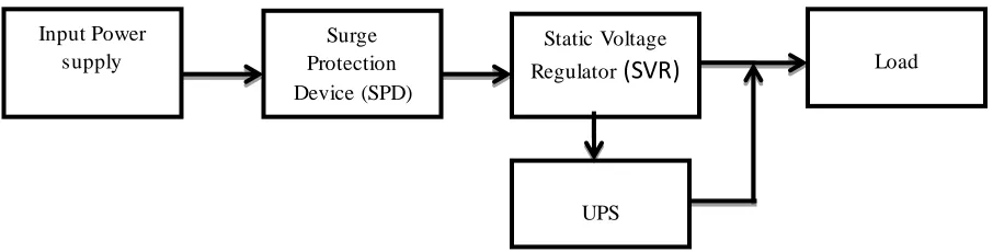
Figure 1: System Model
Static voltage regulators. The figure 1 shows the implementation of system model. The input power supply to the static voltage regulators is provided through the surge protection device. The input power supply may contain transient or surges in it. The function of the surge protection devices is to protect the load from these types of transient or surges. Thus, when any type of transient or surges arises in the input power supply the surge protection devices automatically shut down (trip) the static voltage
regulator which ultimately cuts the power supply to reach to the load. As soon as, the static voltage regulator switched off, the uninterruptible power supplies (UPS) supplies power to the load. The UPS charges through the static voltage regulator in the normal conditions. After particular interval of time when the surges or transients are completely removed from the input power supply the SPD turns on the static voltage regulator. Thus, static voltage regulator again supplies power to load. UPS stops supplying
UPS
Surge Protection Device (SPD)
Static Voltage
Regulator
(SVR)
Load Input Power
IJIRT 144783
INTERNATIONAL JOURNAL OF INNOVATIVE RESEARCH IN TECHNOLOGY217
power to load and starts charging through static voltage regulator.
Due to the emerging technologies in the field of Power Electronics, the Load Tap Changer Voltage Regulator provides steady static voltage Regulator (SVR). The SVR has emerged as a new technology to provide ride through support for facilities in the event of transients under voltage / Over- voltage conditions like sags and surges. The SVR through the use of Static Tap Changers simply regulate the output voltage to 220/230 +/- 5% for an input voltage changes from 140VAC to 290 VAC. The SVR tap changers are designed to respond instantaneously by selecting the appropriate voltage tap on a sub cycle basis.
The Main Components of SVR are:
1) Booster Transformer with its secondary winding
connected in series with the Distribution line.
2) A Regulator transformer with tapped secondary
winding which is connected through taps SCR Switches to the booster transformer primary and the crowbar switch.[1]
The static voltage regulator, though the use of static taps changers, simply regulates the voltage to equipment operational levels. Unlike conventional load tap changes, static tap changes are design to respond instantaneous by selecting the accurate voltage tap on a sub cycle basis, without the necessity to progress through a series of lower voltage taps. The SVR consists of three phase cells and a control
Figure 2: Static voltage Regulator and bypass and isolation switches one-line [1]
and communication cabinet as seen in figure1 each phase cell of SVR is comprised of booster transformer (2) with its secondary winding connected in series with the distribution line, regulator transformer (1) with a tapped secondary winding which is connected through tap SCR switches (3) to the booster transformer primary and the crowbar switch (4).
The SVR is operated in its feed through or no boost mode until the source voltage is above 90% of its nominal value. In this mode, the crowbar SCR switch is closed and all the tap switches are open. The SVR
microprocessor based logic will sense the
instantaneous under voltage level, when the source
© August 2017 | IJIRT | Volume 4 Issue 3 | ISSN: 2349-6002
IJIRT 144769
INTERNATIONAL JO URNAL OF INNOVATIVE RESEARCH IN TECHNOLOGY218
turns off the tap switch when the source voltage returns to the normal range, verifies the tap switch is in fact open and then turns on the crowbar switch, all within the quarter of cycle. The hard wire logic ensures the allowance for SCR recovery time in order to properly respond to specific system conditions, each single phase static tap changer operates independently to give the required boost to each phase.
III COMPARATIVE RESULTS
A. Change in Static voltage regulator output voltage
with respect to input or source voltage for resistive load
Table 1: Output and input voltage of SVR for resistive load
Resistive Load
Input / Source Voltage(Volt)
Output / Load Voltage(Volt)
Average 230.0 222.8
Minimum 195.0 210.0
Maximum 265.0 237.0
Lower
Limit 195Volt (-15%) 218.5Volt (-5%)
Upper
Limit 265Volt (+15%) 241.5Volt (+5%)
Graph 1: Input and output voltage variations with
resistive load
B. Change in Static voltage regulator output voltage
with respect to input or source voltage for inductive load.
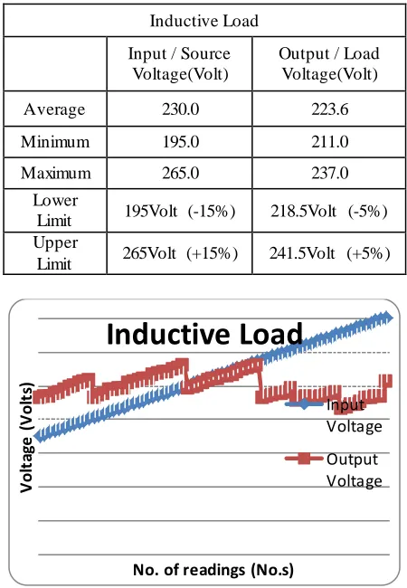
Table 1: Output and input voltage of SVR for inductive load
Inductive Load
Input / Source Voltage(Volt)
Output / Load Voltage(Volt)
Average 230.0 223.6
Minimum 195.0 211.0
Maximum 265.0 237.0
Lower
Limit 195Volt (-15%) 218.5Volt (-5%)
Upper
Limit 265Volt (+15%) 241.5Volt (+5%)
Graph 2: Input and output voltage variations with
Inductive load
C. Change in Static voltage regulator output voltage
with respect to input or source voltage for capacitive load
Table 3: Output and input voltage of SVR for capacitive load
Capacitive Load
Input / Source Voltage(Volt)
Output / Load Voltage(Volt)
Average 230.0 223.6
Minimum 195.0 212.0
Maximum 265.0 237.0
Lower
Limit 195Volt (-15%) 218.5Volt (-5%)
Upper
Limit 265Volt (+15%) 241.5Volt (+5%)
V
ol
ta
ge
(
V
ol
ts
)
No. of readings (No.s)
Resistive Load
phase cell of SVR is comprised of booster transformer (2) with its secondary winding connected in series with t he distribution line, regulator
phase cell of SVR is comprised of booster transformer (2) with its secondary winding connected in series with t he distribution line, regulator
V
ol
ta
ge
(
V
ol
ts
)
No. of readings (No.s)
Inductive Load
Input Voltage
IJIRT 144769
INTERNATIONAL JO URNAL OF INNOVATIVE RESEARCH IN TECHNOLOGY219
Graph 3: Input and output voltage variations with
capacitive load
D. Behavior of Static Voltage Regulator for
Transients / Surge Voltages
1) Acceptance Criteria (Pass/Fail): The Static
Voltage Regulator should supply the transientor surge voltage to load i.e. Load voltage shall be free from “Transient / Surge Voltage”.
2) Sample No. 09 and 10 failure analysis: The surge
applied for serial no. 09 and 10 was not protected by SVR because the particular SVR is designed for 10KV and less then 10KV surge or transient voltage protection.
Table 4: SVR performance for various transient voltages
Sr. No. Transient (KV) Result (Pass/Fail)
1 1.0 Pass
2 2.5 Pass
3 3.5 Pass
4 4.0 Pass
5 4.5 Pass
6 5.0 Pass
7 7.0 Pass
8 8.5 Pass
9 10.5 Fail
10 11.0 Fail
IV CONCLUSION
The results obtained as output voltage of SVR are within a band of +/- 5% which is acceptable voltage
band for various precise electronic devices various types of surge voltages can occurred in electrical and electronics systems. They differs mainly w.r.t. there duration and amplitude depending upon the cause, surge voltage can last for a few 100 microseconds, hours or even days. The amplitude ranges from a few millivolts to some ten thousand volts. Lightning strikes are a special cause of surge voltages. Direct and indirect strikes can result not only in high surge voltage amplitudes but also particularly high and sometimes large current flows, which then have very serious effects. Thus, for the protection of such transient voltage a “surge voltage device” circuit is implemented at the output of SVR.
The device connected to the SVR is protected from the over and under voltage from the power supply in the range of +/- 15 % band along with transient voltage protection which may appear in power supply voltage.
V FUTURE SCOPE
The existing setup of a “Static Voltage Regulator with transient protection” is designed for transient voltage protection up to a 10KV transient voltage. The particular circuit will protect the system from the input voltage variations with +/-15% and maintained the voltage to system within +/-5% tolerance band. And protect the system from a transient of a magnitude up to a 10KV. If the trans ient magnitude exceeds above a 10KV the particular circuit will not detect the same and it will pass to or through the system which may results in a system failure or damage to the particular system.
Thus, a system or a circuit can be designed which will be able to protect the voltage variations to the load along with the transient voltage protection of a magnitude greater than the 10KV. Also the surge protection device can be designed which can protect the consumer appliances from the transient voltages or the surge voltage due to the lightning direct stroke or indirect stroke. As mainly the consumer appliances are protected through the ELCB (Earth leakage circuit breaker) and MCB (i.e. the single phase, 230V AC, 50Hz supply is provided to the domestic consumers) thus the surge voltage which will appear in a supply system for a very short duration will not be detected and protected by the existing ELCB and MCB thus need to add a surge protection device.
V
ol
ta
ge
(
V
ol
ts
)
No. of Readings (Nos.)
Capacitive Load
Input Voltage
© August 2017 | IJIRT | Volume 4 Issue 3 | ISSN: 2349-6002
IJIRT 144769
INTERNATIONAL JO URNAL OF INNOVATIVE RESEARCH IN TECHNOLOGY220
REFERENCES
[1] Eduardo Alegria, Afroz Khan, Janos Rajda and
ShashiDewan,”Static Voltage Regulator (SVR) Ride Through Support For Semiconductor Facilities", POWER WORLD’98 Power Quality Conference, Santa Clara, CA, Nov 1998.
[2] S.M. Bashi,”Micro-controller based Fast
On-Load Semiconductor Tap Changer for Small Power Transformer", International Journal of Applied Sciences, Pg.999 - 1003, Volume 5, Issue 6, 2005.
[3] Li Xiao-ming, Yin Xiang-gen, Wang Wan-qing,
Zhang Shui-Chang,” A Novel Model of Arc less On-Load Tap Changing Transformer & its Simulation", Asian Journal of Information Technology, Pg. 164 - 168, Volume 5, Issue 2, 2006.
[4] H.H. Britten, D.L. Plette,”The Development of a
Static Voltage Regulator for Aircraft A-C Generators", January 1956.
[5] E.L. Harder, C.E. Valentine, “Static Voltage
Regulator for RototrolExciter", AIEE
Transactions, Pg. 601 - 606, Volume 64, August 1945.
[6] Hamid R. Karshenas, Akbar Abdolahi, “Analysis
of Voltage Regulator for Self-Excited Induction
Generator Employing Current-Type Static
Compensator".
[7] P.B. Steciuk and J.R. Redmon, “Voltage Sag
Analysis Peak Customer Service", IEEE
Computer Applications in Power, October 1996.
[8] C.M. summers and T.T. Short, “A Static Voltage
Regulator Insensitive to Load Power Factor ", AIEE Transactions, Vol. 61, Feb 1942.
[9] www.rspowerindia.com
[10] Dr.Rajendra Sawant, Kshitija Sawant, Laxmi
Kanojia, Priyanka Samgiskar, Vishakha
Nevarekar, “Study of Solid State Static Voltage
Stabilizer Using Buck-Boost Converter",
International Journal of Innovative Research in Science, Engineering andTechnology, Vol. 5, Issue 12, December 2016.
[11] www.electricaltechnology.org
[12] M. RabiulAlam, RajibBaran Roy, S.M. Jahangir
Alam, DewanJuel Rahman, “Single phase
automatic voltage regulator design for
synchronous generator”, International Journal of
Electrical & Computer Sciences IJECS-IJENS Vol: 11 No: 05, October 2011.
[13]Jessica Cabiles-Magsino, Rowena Cristina
Guevara, Miguel Escoto Jr., “Implementation of Sliding Mode Control for Current Sharing in Fixed Frequency Voltage Regulator Modules ”.
[14]Matthew E. Oboh, JafaruBraimah, “Single Phase
Automatic Voltage Regulator Design for
Synchronous Generator”, International Journal of Scientific & Engineering Research, Volume 5, Issue 12, December-2014.
[15]Said, Ebrahim A. Badran, M. A. Abd-Allah,
“Mitigation of Very Fast Transient Over voltages at the More Sensitive Points in Gas-Insulated Substation”, International Journal on Electrical
Engineering and Informatics ‐ Volume 4,
![Figure 2: Static voltage Regulator and bypass and isolation switches one-line [1]](https://thumb-us.123doks.com/thumbv2/123dok_us/1395813.1651199/2.612.83.538.281.496/figure-static-voltage-regulator-bypass-isolation-switches-line.webp)