Effect of Plasma Sprayed Metal Matrix Composite
Coatings on Performance of IC Engine
1
N.Poyyamozhi,
2K.Logesh,
3M.Shri harish,
4D.Surryaprakash
1,2,3,4Assistant Professor, Department of Mechanical Engineering, Vel Tech University, Chennai, Tamil Nadu, India
1[email protected], 2[email protected],3[email protected],4[email protected]
Abstract-- The quest for increasing the efficiency of an internal combustion engine has been going on ever since the invention of this reliable workhouse of the automotive world. To achieve this cool giving more attention focused recently by reducing energy cost to the coolant during the power stroke of the cycle. Ceramic creating also has application as thermal barriers to improve the efficiency of the engines by reducing energy loss and cooling requirement. The main aim of the study is to evaluate the effect of ceramic coating on petrol engines effective efficiency at different engine loads and speeds. Experiments were conducted with the three cylinders multipoint fuel injection (MPFI) engine, before to know the coating conditions of the Piston, need to test the Engine at different type of Load and Speed conditions. By using the plasma coating method Ceramic layers are made of Al2O3 based on the NiCrAl bond coat by using base of the plasma coating method the same condition was tested in the ceramic coated research engine as the standard (without coating) engines. The results should be reduction in emission characteristic and an increase in effective efficiency.
Index Term-- Ceramic, Ceramic Coating, Multipoint Fuel Injection engine and Plasma Coating Method.
1. INTRODUCTION
The process of conversion of chemical energy of the fuel into the mechanical energy is done in the internal combustion engines. In internal combustion engine combustion takes place inside a closed combustion chamber. For an engine to work successfully it has to follow a cycle of operation in a sequential manner. This sequence is quite rigid and cannot be changed. Depending on the cycle of operation internal combustion engines are classified into two stroke engines and four stroke engines. Further on the basis of the fuels used they are classified as spark ignition engine and compression ignition engine.
Internal combustion engines are not only competing with other heat engines but in many instances are dominating the field. The class of service is the principal factor in several cases[1].The most outstanding application of internal combustion engine is for all type of transportation, automobiles, trucks and aero planes. In all these cases simplicity of operation and lightweight are the deciding factors. A better utilization of heat energy of fuel is an important feature of internal combustion engine.
Here the work was planning to given energy input is only 25 to 35% used as useful work and the remaining work consists
of the fuel energy is lost in the form of heat of cooling water, exhaust gases and also as unaccounted heat losses are mainly due to the inefficiency of the engine to convert the fuel energy into useful work [2]. The unaccounted loss can be due to some serious errors of measurement, but it almost arises mainly because the fuel has been incompletely burned. Due to this factor emissions as well as low performance of the engine are resulted.
2. ENGINE EMISSIONS
Engine emissions can be classified in to two categories 1. Exhaust emissions, 2. Non-Exhaust emissions
2.1. ExhaustEmissions
1. Unburnt hydrocarbons 2. Oxides of carbon 3. Oxides of nitrogen 4. Oxides of sulphur 5. Particulates 6. Soot and smoke
3. ALUMINUM MATRIX COMPOSITES
Aluminum Matrix composites (AMC) refer to the class of light weight high performance aluminum centric material system. The reinforcement in AMC could be in the form of continuous or discontinuous fibers and whiskers or particulates in volume fractions vary from a few percent values to 70%. Properties of AMC’s can be tailored to the demand of different industrial applications by suitable combination of matrix, reinforcement and processing route. Presently several grades of AMC’s are manufactured by different route.
3.1. Type of AMC’s
AMC’s can be calcified into four types depending on the type of reinforcement, (a) Particle reinforced AMC’s(PAMC), (b) Short fibred reinforced AMC (SFAMC’s) (c) Continuous fiber reinforced AMC(s) (CFAMC) (as Mono-filament reinforced AMC CMFAMC).
3.2. Particle Reinforced Aluminium Matrix Composite
(PAMCs)
5.Ceramics reinforcements are generally oxides or carbides or borides (Al2O3 on Sic) and present in volume fraction less then 30% when used for structural and wear resistance application.
3.3. Impact Test Short Fibered Reinforcement Aluminium
Matrix Composite(SFAMCs)
These composites contain reinforcements with an aspect ratio of greater than 5, but are not continues. Short aluminum fiber reinforced aluminum matrix composites is one of the first and most popular AMC to be developed and used in pistons. This was produced by save age infiltrations process.
3.4. Other AMCs
In continuous fiber-reinforced aluminum matrix composites the reinforcements are in the form of continuous fibers with a diameter less than the given value. The fibers can either be parallel or pre woven.
3.5. Application of AMCs
AMCs now have a proven track record as successful ‘’ high-tech’’ material in a range of applications. AMCs utilization provides significant benefits including performance, economic and environmental benefits. The more number of engineering viability of AMCs have been well documented.AMC having different type of reinforcement found their way too many practical applications.
4. METAL MATRIX COMPOSITES 4.1. Introduction
In recent years, modern technology has created unprecedented demands on materials. There is increasing demand for better materials in the area of dynamic structures which demand high strength and light weight. The efficiency og dynamic structures could be affected by an enhanced structural efficiency of the materials. The dynamic structures include power generation, aerospace accessories, automotive equipment etc.
4.2. Metal Matrix Composites
Metal matrix composites generally comprise high strength and high modulus. They possess high toughness and have high impact properties. They do not yield to changes in temperature or thermal shock. The paramount characteristics range varies from High surface durability effects and low sensitivity to surface defects. They can easily fabricate, shaped, joined and given a smooth finish. The high elastic
properties of alloys which is superior to that found in ceramics is a very useful property that can be used in composites.
4.3. Reinforcement
In the metal matrix system filamentary reinforcement enables very strong reinforcement. The reinforcement filaments combine with three classes of structural engineering metals.
(1) High temperature alloys. (2) Intermediate temperature alloys. (3) Low temperature alloys.
4.4. Reinforcement Selection
The points to be noted in selecting the reinforcements include compatibility with matrix material, thermal stability, density, melting temperature etc. The efficiency of discontinuously reinforced MMCs is dependent on tensile strength and density of reinforcing phases. Chemical and thermal stability of the reinforcement with matrix material is important for material fabrication as well as end application. The thermal discord strain between the matrix and reinforcement is an important parameter for composites used in thermal cycling application. It is a function of difference between the coefficients of thermal expansion of the matrix and reinforcement. The manufacturing process selected and the reinforcement affects the crystal structure.
4.5. Matrix Selection
Thermodynamically stable dispersions are essential for the use of metal matrix composites for high temperature applications .This can be done by using an alloy dispersion system minimize the solid state diffusion, interfacial energies and elemental solubility. Aluminum and magnesium alloys are regarded as widely used matrices due to low density and high thermal conductivity.
4.6. Matrix-Reinforcement Interface
The interface between the matrix and the reinforcement is important as the properties of this region dictate load transfer and crack resistance of MMCs during deformation. it is necessary to control chemical interactions and reduce oxide formation and improve wetting to enhance the interfacial bond strength in metal matrix composites .
4.7. Interaction Zone
initiation of interfacial reactions wetting to certain extend is desired. The thermodynamic potential of the elements involved will determine the extent and products of these interfacial reactions.
4.8. Interface Bond Strength
A detailed analysis of the interfacial bond strength in MMCs is not available due to the lack of basic knowledge of the interfacial properties of these systems and the various ceramic matrix combinations. To Measuring the values of interfacial shear strength directly has been restricted to punch and fiber pun out tests.
4.9. Fabrication Method
In 1970 new fabrication methods of metal matrix composites were developed. Improved processing leading to a near net shape composite component in a economic manner is the call of the hour. Although numerous technique depend on choice of materials choice of reinforcements
4.10. Solid State Fabrication Technique
Among the various methods available to fabricate metal matrix composites using this technique power metallurgy and diffusion bonding are extensively used. Others include hot trolling, explosive welding, extrusion, drawing, pneumatic impaction etc.
4.10.1. Powder Metallurgy Technique
This is the most perform method used for the manufacture of MNCs with discontinuous reinforcement, using either whiskers or particulates as the reinforcements. In this method; the mixture of powdered matrix material and reinforcement are fed into a mould of required amount shape and it’s then compacted under pressure. This is called cold pressing[3]&[4]. After this the compact is then heated to sufficiently high temperature to develop considerable solid state diffusion to facilitate bonding between the powdered particles .The blended mixture is directly pressed by hot pressing. After few secondary operations; the consolidated product is used as a MMC material.
4.10.2. Diffusion Bonding
Generally MMCs with sheet or foils of matrix material are fabricated using this method. This method involves the chemical surfaces treatment of the metal in the form of sheets and reinforcing material in the form of fiber for efficient inter diffusion. The fibers are later oriented in a predetermined fashion on a metal foil and pressed to ensure
bonding. Supplementary machining is carried out after bonding [4].
5. PLASMA SPRAY MACHINES
In normal plasma spray process an electric arc is struck between a rod type cathode and a nozzle anode. Whenever the plasma gas flows through the arc and it gets ignited. When electrons are accelerated the plasma also gets ignited from the cathode to the anode. As the electrons speed varies towards from the anode and they colloid with excite and ionize the atoms or molecules in the gas.
The molten powders on hitting the substrate cool and anchors together form a strong adherent Coating and its mainly used for making a protective coating of metals. Applications of ceramic alloys are
Corrosion, erosion and abrasion resistant coatings Rebuilding the salvaging of mismachined jobs Thermal barriers coatings, high temperature
electrically insulating and conducting coatings. Preparation of special coatings like superconducting
coatings etc.
5.1. Types of Plasma Spray Technique
Atmospheric Plasma Spraying(APS) Vacuum Plasma Spraying(VPS)
Shrouded Plasma Spraying /Reactive Plasma Spraying (RPS)
Controlled Atmosphere Plasma Spraying –Low
Pressure/High Pressure (CAPS) Under Water Plasma Spraying (UPS) Solution Precursor Plasma Spraying (SPS)
High Energy Water Stabilized Plasma Spraying (HEPS)
5.2. Principles of Atmospheric Plasma Spraying
The Plasma generator consists of a circular anode and usually it’s made up of copper and cathode of theoriated tungsten. The Electric arc discharge supported by a generator through connectors heats up the working gasses. Which expand to the atmosphere forming a jet. The powder suspended in a carrier gas and it is injected in the flame. The particles of the powder after being melted and accelerated in the plasma impact the substrate and form the coating [5].
5.3. Process Parameters
Arc Plasma,
+ , typically flow rate is about 40+50lpm, in some installations up to 80 lpm. Temperature of the plasma typically is in a range between 14,000 K – 30,000 K and its velocity at the nozzle exit can reach 800m/s or even more. Electric Power is typically up to 60kW in some installations however more than 100kW.
5.3. Coating Properties
The bond strength of plasma sprayed ceramic materials is typically in the range 15-25Mpa. The plasma Sprayed bonding alloys (as NiAl,NiCrAl, NiCrAlY, mo etc.,) may reach strength in excess of 70Mpa.
5.4. Application
APS chromium oxide coatings are widely applied on drilling components which considerably lengthens their service life and Plasma sprayed stainless steel 316L powder is widely used as Chemical Barrier anti corrosive coating on vessels in chemical refineries. Diamond like carbon coatings can be made over semi conductor microelectronic circuits using plasma spray technique [7] & [8].
6. ALUMINUM OXIDE
Aluminum oxide (Al203) is referred to as the combinations of
Alumina, Corundum, Sapphire ruby or aloxite in the mining and also that includes ceramic and materials science communities [6] and also it’s mentioned that amphoteric oxide of aluminum.
6.1. Natural Occurrence
Corundum is the most common naturally occurring crystalline form of aluminum oxide. Much less common rubies and sapphires are gem-quality forms of corundum with their characteristic colors due to trace impurities in the corundum structure. Aluminum oxide is an electrical insulator but has a relatively high thermal conductivity (40 W/mK). In its most commonly occurring crystalline form called corundum or a-aluminum oxide, its hardness makes it suitable for use as an abrasive and as a component in cutting tools.
6.2. Procedures for Gasoline as Fuel
Before starting the process check the fuel level in fuel tank and water flow and whether the engine is on no-load conditions.
Fig. 1. Experimental setup
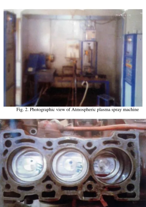
Fig. 2. Photographic view of Atmospheric plasma spray machine
Fig. 4. Photographic view of coated piston
The engine is started by switching the hand electric switch. Then it’s allowed to run for 5 to 10 min to attain steady state. Then the gear is loading device and run 5 min. The time take of 30cc of fuel consumption. The temperature of water inlet & outlet temperature were taken. Both the inlet and outlet temperature also measured .load & speed is applied and the fuel consumption is noted [7], [9].
7. RESULT AND DISCUSSION
In given below the results of the experimental investigations are presented and discussed
Carbon Dioxide
Fig.5 Speed test the level is slightly increased for coated piston but speed of 2600 rpm a nominal will be reduced.Fig load test the level is inially slightly increased but after 60% of load will be reduced.
Hydrocarbon
Fig.6 speed test the HC level decreased at 3000 rpm compared to the sole piston. Fig load test the HC level is almost decreased for all load conditions of the coated piston compared to the sole piston.
Carbon Monoxide
Fig.7 speed test the CO level is almost decreased for coated piston compared to the sole piston and load test the CO level is considerably decreased for coated piston compare to the sole piston.
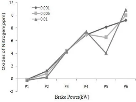
Oxide of Nitrogen
Speed test the Nox level is increased for coated piston compared to the sole piston because of having a good thermal insulation.
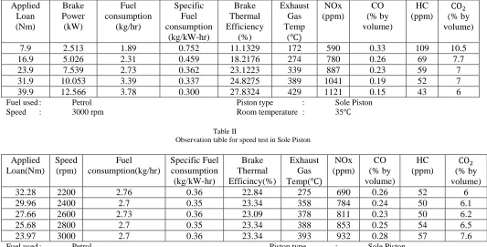
Table 1
Observation table for Load test in Sole Piston
Fuel used : Petrol Piston type : Sole Piston Speed : 3000 rpm Room temperature : 35
Table II
Observation table for speed test in Sole Piston
Fuel used : Petrol Piston type : Sole Piston Laod : 7.53 B.P Room temperature : 35
Applied Loan (Nm) Brake Power (kW) Fuel consumption (kg/hr) Specific Fuel consumption (kg/kW-hr) Brake Thermal Efficiency (%) Exhaust Gas Temp ( NOx (ppm) CO (% by volume) HC (ppm) (% by volume)
7.9 2.513 1.89 0.752 11.1329 172 590 0.33 109 10.5
16.9 5.026 2.31 0.459 18.2176 274 780 0.26 69 7.7
23.9 7.539 2.73 0.362 23.1223 339 887 0.23 59 7
31.9 10.053 3.39 0.337 24.8275 389 1041 0.19 52 7
39.9 12.566 3.78 0.300 27.8324 429 1121 0.15 43 6
Applied Loan(Nm) Speed (rpm) Fuel consumption(kg/hr) Specific Fuel consumption (kg/kW-hr) Brake Thermal Efficincy(%) Exhaust Gas Temp( NOx (ppm) CO (% by volume) HC (ppm) (% by volume)
32.28 2200 2.76 0.36 22.84 275 690 0.26 52 6
29.96 2400 2.7 0.35 23.34 358 784 0.24 50 6.1
27.66 2600 2.73 0.36 23.09 378 811 0.23 50 6.2
25.68 2800 2.7 0.35 23.34 388 853 0.25 54 6.5
Fig.8 load test the NOx level is always increased for coated piston compared to the sole piston. Good thermal insulation surrounding the combustion chamber.
Brake Thermal Efficiency
Fig.9 Speed test the brake thermal efficiency for coated piston is almost increased compare to the sole piston.
Fig. 5. Brake Power vs Carbon Dioxide
Fig. 6. Brake Power vs Hydrocarbon
Fig. 7. Brake Power vs Carbon Monoxide
Fig. 8. Brake Power vs Oxide of Nitrogen
Fig. 10. Speed vs Oxides of Nitrogen
8. CONCLUSION
The following items were defined from this investigation of three cylinders, MPFI, Water cooled, Metal matrix composite petrol engine.
During the combustion to prevent the excessive heat loss, the entire coating material has been applied successfully to the combustion chamber as the thermal barrier coating of a petrol engine. During the insulation the entire heat loss has
been reduced to the cooling system and an engine made some effects on the cylinder walls to become hotter and increase the effective efficiency rapidly.
During the combustion chamber insulation that heat rejection value has been reduced as well as effective efficiency also not improved to the same extends.
REFERENCE
[1] R. Gonzalez, A. McDonald, P. Mertiny, 2013, Effect of flame-sprayed Al–12Si coatings on the failure behaviour of pressurized fibre-reinforced composite tubes, Polymer Testing, Volume 32, Issue 8, December 2013, Pages 1522-1528.
[2] Jing MA, Dong-qing YAN, Jian-wen HU, Xin ZHANG, Yang LI, 2013, Reactive HVOF sprayed TiN-matrix composite coating and its corrosion and wear resistance properties, Transactions of Nonferrous Metals Society of China, Volume 23, Issue 4, April 2013, Pages 1011-1018.
[3] X. Zhou, Raj Siman, Lin Lu, Pravansu Mohanty, 2012, Argon atmospheric plasma sprayed hydroxyapatite / Ti composite coating for biomedical applications, Surface and Coatings Technology, Volume 207, 25 August 2012, Pages 343-349. [4] S. Yugeswaran, A. Kobayashi, K. Suresh, K.P. Rao, B.
Subramanian, 2012, Wear behavior of gas tunnel type plasma sprayed Zr-based metallic glass composite coatings, Applied Surface Science, Volume 258, Issue 22, 1 September 2012, Pages 8460-8468.
[5] Chaiwut Gamonpilas, Esteban P. Busso.2009, A mechanistic approach to extract the mechanical properties of individual constituents in plasma-sprayed metal matrix composite coatings, Surface and Coatings Technology, Volume 204, Issue 4, 15 November 2009, Pages 440-447.
[6] Hyun-Ki Kang, Suk Bong Kang, 2006, Thermal decomposition of silicon carbide in a plasma-sprayed Cu/SiC composite deposit, Materials Science and Engineering: A, Volume 428, Issues 1–2, 25 July 2006, Pages 336-345.
[7] Y.W Gu, K.A Khor, P Cheang,2003.In vitro studies of plasma-sprayed hydroxyapatite/Ti-6Al- 4V Composite coatings in simulated body fluid (SBF), Biomaterials, Volume 24, Issue 9, April 2003, Pages 1603-1611.
[8] Bang-Yen Chou, Edward Chang,1999,Microstructural characterization of plasma-sprayed hydroxyapatite–10 wt% ZrO2 composite coating on titanium, Biomaterials, Volume 20, Issue 19, October 1999, Pages 1823-1832.
[9] R.A. Pike, V.M. Patarini, R. Zatorski, F.P. Lamm,1992, Plasma-sprayed coatings as adherend surface pretreatments, International Journal of Adhesion and Adhesives, Volume 12, Issue 4, October 1992, Pages 227-231.