Sidelobe Reduction using Frequency
Modulated Pulse Compression Techniques in
Radar
Raghupatruni Jeevanmai1 and Dr. N. Deepika Rani2
I.INTRODUCTION
In Pulsed Radar system design, the emphasis is on resolving closely spaced multiple targets i.e. "range resolution" and to cover larger range area with "less transmitted peak power". These Radar metrics depends on the waveform attributes such as pulse duration and bandwidth. A narrow pulse is required to achieve high range resolution and long duration pulse is required to improve the detection performance of radar. Thus, there exists a trade-off between range resolution and detection performance. To mitigate this limitation, pulse compression techniques are adapted. These techniques transmit longer duration pulse that will have bandwidth corresponding to a shorter pulse to achieve high range resolution. Pulse Compression techniques are used to enhance the performance metrics of the radar.
The rest of the paper is organized as follows. Matched Filter is introduced in section II. Need for pulse compression techniques are discussed in section III. Frequency modulated pulse compression techniques are explained with simulated results in section IV. Concluding remarks are given in section V.
1Department of Electronics and Communication Engineering Gayatri vidya Parishad(A),
Visakhapatnam, Andhra Pradesh, India
2Department of Electronics and Communication Engineering Gayatri vidya Parishad(A),
Visakhapatnam, Andhra Pradesh, India
DOI: http://dx.doi.org/10.21172/1.73.524
e‐ISSN:2278‐621X
Abstract- The main objective in a pulsed radar system design is to improve range resolution and
detection performance of radar. Pulse Compression is a signal processing technique that utilizes the benefits of high range resolution ability of short duration pulse and large range detection ability of long duration pulse. However, the pulse compression filter output in the radar receiver results in higher peak side lobe levels which are not acceptable in many systems when weaker targets are encountered. Thus, higher peak sidelobe levels affect the detection performance of the radar. In this paper, focus is given on which frequency modulated pulse compression technique achieve lower peak side lobe levels.
Keywords – Pulse Compression, Peak Sidelobe Level(PSL), Linear Frequency Modulation(LFM),
II.MATCHED FILTER
Good receiver design is based on maximizing peak signal to mean noise ratio. In order to maximize the signal to noise ratio at receiving stage of radar set, matched filter is the optimum solution. The impulse response of matched filter in time domain is expressed as
where δ is the gain constant often set equal to unity, Tn is the instant at which maximum peak signal to mean noise ratio occurs. For filter to be causal, Tn is considered as . The complex envelope of a transmitted waveform which is given as input to the matched filter is given by
For this input signal x(t), the output of the matched filter is attained by convoluting the received signal(x(t))with its impulse response h(t).
III.NEED FOR PULSE COMPRESSION TECHNIQUES
Resolution and Maximum range detection of targets are the two important parameters to be considered while designing the radar waveform because, these metrics depend on waveform attributes such as pulse width, bandwidth, modulation.
A. Range Resolution –
Resolution is the ability of radar to resolve two or more targets at different ranges but on same bearing . For a simple constant-frequency pulse, the resolution in range dimension is
In case of Simple pulse, range resolution depends on pulse width. Thus, a shorter pulse width is required for better range resolution
B. Long Range Detection of targets –
A simple pulse have only two attributes, its amplitude(A) and pulse width. The energy in the pulse is product of peak power and its pulse width, which is given as
Detection performance of radar can be improved by maximizing the pulse energy. The amount of energy in the pulse is proportional to the peak power and pulse duration. The higher peak power is required to accommodate enough energy for transmission of the pulse. Due to the constraints on the radar components to withstand high peak power, design of high power transmitter and receiver is a hectic task. Thus, another alternative to maximize pulse energy is to increase the width of the pulse.
C. Pulse Compression –
For improving range resolution a shorter pulse is required, whereas for improving long range detection performance of radar a longer pulse width is required. Thus, there exists a trade-off between range resolution and large detection of targets. To mitigate this limitation, Pulse Compression techniques are adapted.
Figure 1. Pulses having same energy with different durations.
(b) High range resolution can be obtained by using Linear Frequency modulation(LFM) to widen the signal bandwidth.
IV.FREQUENCY MODULATED PULSE COMPRESSION TECHNIQUES
The time bandwidth product of simple pulse waveform is unity whereas in the pulse compression waveform the bandwidth β is much greater than the pulse width, which can be obtained by adding frequency modulation to a simple pulse.
A. Linear Frequency Modulation(LFM)
Linear Frequency Modulation is used in radar systems to attain wide-operating bandwidths. In this case, the frequency of the transmitted wave either increases (up-chirp) or decreases (down-chirp) with time. The instantaneous frequency of linear frequency modulated waveform is stated as[1]
Using eq.(5), instantaneous frequency of LFM is plotted in Fig 2.
Figure 2. Instantaneous frequency of LFM with and
From Fig.2, it is clear that frequency is linearly swept through the entire duration. The matched filter output for LFM signal is given by [1]
The first null occurs when numerator is simplified[1], leading to Rayleigh resolution of 1/β seconds and correspondingly the range resolution is given by
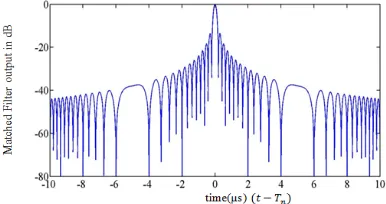
Eq.(7) shows that the range resolution of LFM is inversely proportional to swept bandwidth, unlike the simple pulse. The bandwidth and pulse duration in LFM can now be used to separately control pulse energy and range resolution. However, the LFM matched filter output exhibits sidelobe behavior as shown in Fig. 3.
From the Fig.3, it is observed that the peak side lobe level is obtained at-13.9dB which results in target masking effect, when multiple targets are available in the radar field of view. Therefore, in order to reduce the side lobes, the techniques such as piece wise linear frequency modulation are adapted.
B. Two-stage Piece Wise Linear Frequency Modulation(PLFM)
PLFM is a class of frequency modulated pulse compression technique in which sweep rate is not restricted to constant as compared to the LFM. PLFM comprises of concatenated LFM signals with distinct sweep rates. The frequency of each stage is swept linearly through the given time frame. Piece wise linear frequency modulation is carried out in two and three stages. The instantaneous frequency of two-stage PLFM is given by
The phase of the two-stage PLFM is obtained by integrating eq.(8 )
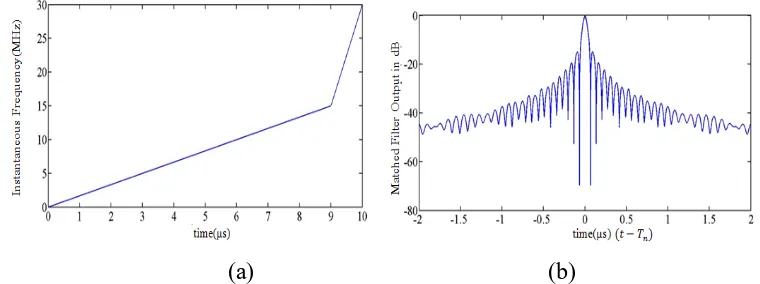
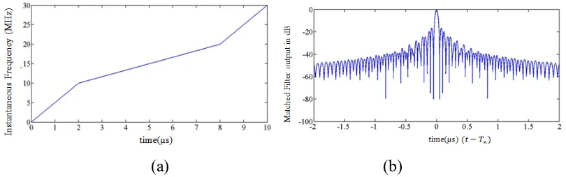
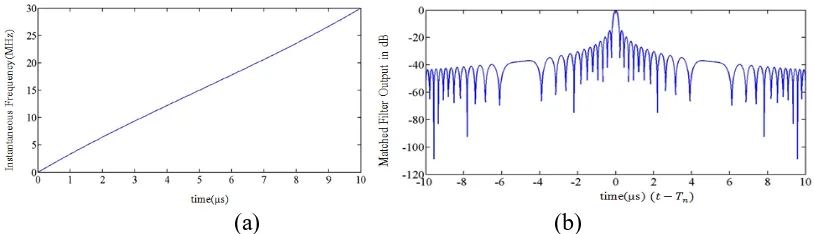
T1 denotes the instant at which the sweep rate changes. By substituting eq.(9) in eq.(2), the complex envelope of PLFM is obtained. Figure 4 to Figure 7 shows instantaneous frequency of two-stage PLFM of duration , β1=15MHz, β=30MHz and its corresponding matched filter output with different T1.
(a) (b)
(a) (b)
Figure 5. (a)The instantaneous frequencyof two-stage PLFM with T1=1µs(b)corresponding matched filter output
(a) (b)
Figure 6. (a)The instantaneous frequencyof two-stage PLFM with T1=8µs(b)corresponding matched filter output
(a) (b)
Figure 7. (a)The instantaneous frequencyof two-stage PLFM with T1=2µs(b)corresponding matched filter output
Table -1 Peak Side lobe level of two-stage PLFM for different values of T1
T1 Peak Side
Lobe Level(PSL)
9 -14.87
1 -15.92
8 -16.46
2 -16.78
From the Fig.4 to Fig.7 and from Table 1, it is observed that the peak side lobe level is reduced only when the sweep rate is altered at the pulse edges. PSL of two-stage PLFM is reduced by 2dB when compared to the LFM signal. Besides the two-stage PLFM, tri-stage PLFM is another frequency modulation pulse compression technique to reduce the sidelobes without degrading the resolving capability of Radar
B. Tri-stage Piece Wise Linear Frequency Modulation –
The phase of the tri-stage PLFM is obtained by integrating eq.(10)
By substituting eq. (11) in eq.(2) complex envelope of Tangent-based NLFM is obtained and this is given as input to the matched filter. Fig.8(a) and Fig.8(b) shows instantaneous frequency of tri-stage PLFM of duration ,β=30MHz and its corresponding matched filter output.
(a) (b)
Figure 8. (a)The instantaneous frequencyof tri-stage PLFM with β=30MHz ,T1=2µs, T2=8µs, β1=10MHz , β2=20MHz (b)corresponding matched filter output
From the Fig.8(a) it is clear that tri-stage PLFM consists of three LFM stages that increases the sweep rate at the leading and trailing edges of the waveform. From Fig.8(b) it is observed that the peak side lobe level is -17.5dB which is lowered when compared to the conventional LFM signal and two-stage PLFM signal. Instead of piece wise linear frequency modulation, the sweep rate is varied at every instant to observe the improvement in performance metrics
B. Tangent-based Non Linear Frequency Modulation(NLFM) –
The instantaneous frequency modulation function of this class NLFM is based on the tangent function[4]
where , α≥0 is sidelobe control factor, β is the bandwidth of tangent-based NLFM. The phase function of tangent based NLFM is obtained by integrating eq.(12)
(a) (b)
Figure 9. (a)The instantaneous frequencyof tangent-based NLFM with α=0.5(b)corresponding matched filter output
(a) (b)
Figure 10. (a)The instantaneous frequencyof tangent-based NLFM with α=1(b)corresponding matched filter output
(a) (b)
Figure 11. (a)The instantaneous frequencyof tangent-based NLFM with α=2(b)corresponding matched filter output
Figure 12. (a)The instantaneous frequencyof tangent-based NLFM with α=3(b)corresponding matched filter output
Table -2 Peak Side lobe level of tangent-based NLFM for different values of α
Peak Side Lobe Level(PSL)
0.5 -15.13
1 -19.22
2 -24.03
3 -34.96
From the Fig. 9 to 12 and Table 2 it is observed that by varying α , there is reduction in PSL from -15.13dB to -34.96dB improving detection performance of radar despite of main lobe width broadening. Hence, to further reduce the sidelobe levels without increasing the main lobe width, hybrid-NLFM is implemented.
B. Hybrid Non Linear Frequency Modulation(NLFM) –
Hybrid NLFM is a result of an empirical research work done by Price[2]. In this technique, instead of piece wise change in sweep rates continuous non-linearity in frequency modulation can be implemented by using eq.(4.8). This design gives the instantaneous frequency of NLFM as
The parameter represents Linear Frequency Modulation term, while the parameter βc is designed to approximate a chebyshev-shaped spectrum i.e. constant side lobe level. The phase of NLFM is obtained by integrating the instantaneous frequency given in eq.(4.8)
(a) (b)
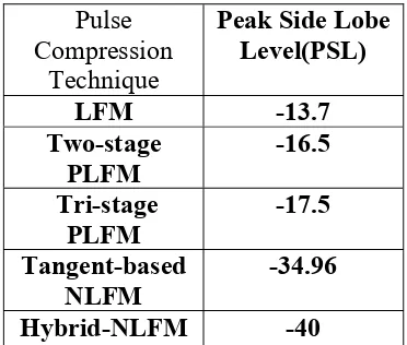
Table -3 Comparison of Frequency modulated Pulse Compression Techniques with
Pulse Compression
Technique
Peak Side Lobe Level(PSL)
LFM -13.7
Two-stage PLFM -16.5 Tri-stage PLFM -17.5 Tangent-based NLFM -34.96
Hybrid-NLFM -40
From the Table 3 it is observed that LFM has higher peak side lobe level, by employing piece wise linear frequency modulation and non linear frequency modulation, the side lobe levels have been reduced to greater extent
V.CONCLUSION
Linear Frequency Modulated pulse compression technique results in higher peak side lobe level in the matched filter output which leads to target masking. Subsequently, piece wise linear frequency modulated pulse compression technique is analyzed in both two and three stages. Using this technique, it is concluded that peak side lobe levels has been reduced by almost 2dB compared to the LFM without compromising the resolving capability of radar. In order to further reduce the peak sidelobe levels, Non linear Frequency Modulated Pulse Compression techniques are analyzed. One of its type is Tangent based NLFM. This technique results in lower peak sidelobe levels compared to the LFM and PLFM despite main lobe broadening. To mitigate this, Hybrid NLFM is analyzed in this paper. This technique reduced the peak sidelobe level to the greater extent without compromising the range resolving capability of radar.
REFERENCES
[1] M.A. Richards, "Fundamentals of Radar Signal Processing", McGraw-Hill, New York, NY,USA,2005.
[2] M. I. Skolnik, "Introduction to Radar Systems",3rd Edition,McGraw-Hill, New York,2008.
[3] C.D. Rawat and Anuja D. Sarate, "High Resoultion LowPower Radar Pulse Compression Techniques", International Journal of Advanced Research in Electrical, Electronics and Instrumentation Engineering, Vol. 3, Issue 4,pp. 8928-8935,2014.
[4] Y.K. Chan, M.Y.Chua and V.C. koo, "Sidelobes reduction using simple two and tristages nonlinear frequency modulation", Journal of progress In Electromagnetic Research, vol. 98, pp.33-52,2009.
[5] Chandan kumar, "Development of EfficientRadar Pulse Compression Techniques for frequency modulated pulses", thesis for degree of masters with National Institute of Technology Rourkela available at http://ethesis.nitrkl.ac.in/3027/1/Thesis.pdf, 2014.
[6] S. Boukeffa, Y. Jiang and T. Jiang, "sidelobe reduction with nonlinear frequency modulated waveforms", in Signal Processing and its Applications(CSPA), IEEE 7th International colloquium,