Mechatronics Engineering Implementation of
multilevel control of a complex hybrid robot
Farah Salem, Alsaba Michel, Aldayoub Ziad
Higher Institute for Applied Sciences and TechnologyDamascus, Syria
[email protected] [email protected]@hiast.edu.sy
Abstract— Multifunction robots are distributed systems
need to interface to highly heterogeneous hardware. Robotics researchers have focused on developing new methods and techniques for solving many difficult functional problems, but remained independent of the mechanical design, and performed algorithms test usually just after realization of the physical prototypes. However, realization of physical prototypes is, usually, a complex and expensive process.
This paper presents a practical way to build a general model of multilevel control of a complex robot in MATLAB-Simulink®, as well as the implementation of asked tasks and missions. Our most important focus point is the communication between the control structure and the mechanical model in ADAMS® environment, which permits the so true whole system modeling, and testing the mechanical response to orders come from the control levels and supervisor command. It also aims to create a structure within MATLAB-Simulink® environment similar to the way of constructing software components and build a library of control and supervisory components that allows mechatronics programmers to easily construct robot program. Finally, this structure will be applied to simulate a complex practical system, which is the Wheeled Hybrid Mobile Robot.
Index Term— robot, hybrid, co-simulation, component, multilevel, supervisor, mechatronics
I. INTRODUCTION
The co-simulation modeling technology is based on ADAMS® and MATLAB-Simulink® software [1]. This technique is a useful tool for improving and developing engineering design, allows the study of designs of mechanical systems with mechanical structure and complex dynamics and their control system. Where the mechanical system is built in the ADAMS® environment and used instead of a simplified system as in traditional studies, then define the input and output system control and send to MATLAB-Simulink®, where we build the control system. This method simplifies simulation and makes its results more accurate and reliable, leading to highly efficient designs. In participatory modeling, the control of the lower and higher levels is modeled and the use of the supervisory control is not addressed because of the difficulty of modeling it, especially with complex systems that perform complex tasks.
Multifunction robots are distributed systems where there are a number of sensors, controls, and motors. Moreover, its services are becoming more sophisticated. Allowing them
to operate independently while providing complex services in an unknown or partially known environment, it also requires the operation of a number of algorithms at the same time, these algorithms cooperate to perform specific tasks. But its services are unusable even if a slightly different is required. As well as increased demand for modularity, productivity, and reusability.
This great complexity in the structure and control of robots leads to complex software. The programs are divided into small independent components, each component consisting of the interface and the context. Its components can be developed independently of other components. It is responsible for solving a specific problem. The components interact with each other, allowing the building of complex systems and facilitating complexity handling at the design stage.
This method allows designers to focus on the work of each component separately from other components, so any component can be developed or replaced without affecting the rest of components and allows the addition of new components easily. This method is used to build the supervisory control and control system in many systems such as ITER RH (International Thermonuclear Experimental Reactor)[2] where the security and fail tolerance is essential criteria, a subsystem of ITER which contains the programs responsible for planning maintenance operations, a set of tasks required and each task consists of a set of sub-tasks which consist of a set of procedures. The control system of ITER is divided into two layers (Fig .1):
1. Supervisory control layer: This layer contains subsystems responsible for the equipment management, processes, and plant safety.
2. Equipment control system: This sub-system contains software modules for planning and control of equipment required for carrying out maintenance activities. For each such device, there is one control system consisting of a high-level control and a low-level control.
In social service robots provided with a mobile base, arm and sensor systems, ROS (Robot Operating System) was used to integrate sensor, planning, coordination, and control techniques[3]. The ROS system has been very popular and has seen significant growth over the past years. It is based on the principle of components. Each component performs repetitive calculations and allows it to communicate with other components through interaction patterns as shown in Fig.2.
Fig. 2. Architectural Diagram [3]
Component technology seems to be an attractive approach to meet the demands in the robotic software field [4]. Widely used component technologies such as EJB [4], .NET [5], and the CORBA component model [6], recently some research has actively been conducted on component-based robot software platforms [7]-[8]. Many software platforms have also been developed to deal with components such as MSRDS [9], MARIE [10], OROCOS [11], RT-Middleware [12], ROS [13], and OPRoS [14], GenoM [15] aim at providing interfaces for accessing robot sensors and actuators over the network. ERSP [16], Urbi [17], Mobile Robots [18], and iRobot Aware [19] are robot software architecture platforms that provide layered software architecture. The following points can be observed [25]:
They have the same type of component interfaces.
Most component models lack an explicit concept of connectors.
They have similar finite state machine categories for life cycle management.
There is no systematic approach to reuse software across the systems.
There is no connection with the mechanical system, to study the ability of this system to implement the orders come from the control levels, supervisor command.
In [24] proposes a hybrid and dynamic architecture, called ORCA: Architecture for an Optimized and Reactive Control. ORCA is generically thought to be applicable to many case studies. It is divided into three main layers: the System Layer, the Local control layer and Global Control layer (Fig.3).
Fig. 3. Organic Robot Control Architecture ORCA [24]
By comparing several studies [2-3-24] we note the following points:
There is a similarity between them in terms layers distribution and distinguished in splitting some layers and components.
The first layer represents the physical model and the second layer contains the control could be divided into low level and high level control layers. The last one is the supervisory layer and it is responsible for decision-making [2].
In addition, many safety factors have been taken into account because of the seriousness of the work [2].
Building components in MATLAB-SIMULINK® environment is characterized by the following:
Taking advantage of already builded blokes and units within MATLAB®.
The graphical method makes the implementation process more visible and thus facilitates the detection, identification and errors resolution.
The MATLAB® is the most widely used program in the field of control and is therefore familiar to the control engineers, mechatronics and even communications and IT engineers, enabling them to work directly without the need to learn new software.
The possibility of connecting with the ADAMS® allows dealing with a real model of the mechanical system without the need of a manufactured prototype, which saves a lot of money, effort and time.
II. METHODOLOGY OF CONTROL SYSTEM DESIGN
a new forth level, that will be responsible for performing the basic tasks; it also contains components to protect the robot in order to reduce the work of the last level, which represents the brain of the robot.
The distribution is based on an easy methodology that can be easily used by mechatronics engineers and does not require much knowledge in the informatics. It also makes it easier for IT engineers to build a supervisory control and control program.
Robot control is a motor controller and each motor needs a low level of control receives commands from its high-level control and in turn provides feedback about its progress. The high-level control system is either the driver component of operator part like the base or arm, which controls one or more motors to perform the required movement from this part. The previous sections represent the first three levels. The fourth level carries out a specific task that may require controlling more than one part of the robot, leaving the task of planning and tracking the execution of user commands, monitoring task and robot safety to the last level. This structure allows the addition of new components or the development or replacement of any component easily without the need to modify other components. It also allows focusing on component building independently of other components. The component is built, tested, and then added to the component library. This approach originates in the structure of graphical components that form a direct link between design and implementation and allow the construction of the structure easily, clearly and comprehensively by mechatronics Engineers.
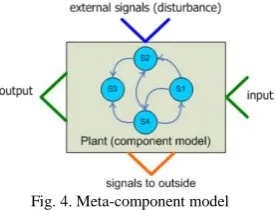
In a similar way, we could use components to build control programs. To build control programs as in [25] they introduce a generic description for the component "meta-component model", which specifies generic input and output signals as well as general internal dynamics of a component. We assume that this meta-component has four kinds of I/O signals (Fig.4):
1. Two for input/output or data flow (green arrows)
2. Two for ingoing/outgoing commands or execution flow (blue and orange arrows).
Fig. 4. Meta-component model
This assumption draws from the control theory domain and based on the common denominator of I/O signals for a physical plant. In most of the contemporary software systems, the internal dynamical model is represented by a finite state machine, In case of the internal dynamical model of the component, it is often free form and could be represented in Petri nets, which includes building method that guarantees
certain correctness properties (i.e. behavioural properties like deadlock-free or liveness, reachability, etc.). This structure is
compatible with MATLAB-Simulink® programming
capabilities. The final step is to be built a virtual prototype in ADAMS® environment, which provides the dynamic model of the robot in a consistent manner with the accuracy of the virtual prototype, thus high accuracy can be obtained. Then connect the structure with the virtual prototype in ADAMS®. Modeling of the system, both the control and mechanical, which allows validation of the algorithms of supervisor and control and the ability of the system to respond to orders and give us a clear picture of the necessary sensors during design.
STRUCTURE
III. SECTIONS STRUCTURE
As we have above already mentioned, this structure consists of five levels
A. Hardware Level
Each hardware device like the joystick, the platform, the arm, the camera etc. must have a driver component. A driver component reads data from the device and publishes them on one or more topics. The devices are divided into two types:
Passive device: like cameras, sensors and joysticks. Then Hardware Level only reads data from the device and publishes them (Fig.5).
Active device: actuators (platform or arms). Then Hardware Level subscribes to one or more topics that broadcast command messages, and reads data from the device and publishes them (Fig.5).
Fig. 5. Active and Passive device
B. Low -Level Control
Actuated devices require a dedicated controller component to control their movements based on the last received goal. For this purpose, the use of feedback-based control algorithms, like the Proportional-Integral-Derivative (PID). It get feedback through the Hardware Level components and the desired goal of High-Level Control. Whenever a goal specifying the desired state of the actuated device is received, it is compared against the current. If the desired and actual state of the device are not equal then a sequence of commands are published to the corresponding driver component, such that the actuated device converges on its goal as soon as possible.
C. High-Level Control
This level controls the work of robot parts (platform, arm, and grip). It consists of the following components:
component is run by a target sent from the robot management level, as well as information about the current state of the robot part. It moves this part of its current location to reach the desired goalby sending commands to the Low-level control components of its associated and received information about and send it to the higher levels.
Auto-Manual Switch component: This level contains a switch for each of the robot parts management component; the switch determines its mode of operation (manual or automatic).
Kinematic transformer component (KT): contains the direct and inverse model of the robot. It stores the current configuration of the robot andCoordinates of the center of gravity of the robot; the kinematic is kept up-to-date by subscribing to data being published by driver and localization components and makes it available to the of the higher control levels components.
D. The robot management level
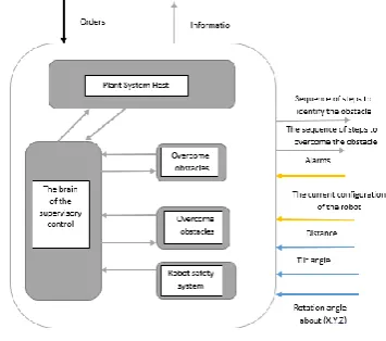
Fig. 6. Robot management level
This level contains a number of components that manage the implementation of tasks and control the sensors of the robot and contains the following main components (Fig.6):
Main mission implementation component: Contains the main functions of the robot parts and implements them based on a specific sequence sent from level of supervisor, it control the High-Level Control components to perform these tasks.
Monitoring of external sensors component: Its task is to detect obstacles in front of the robot. When the robot reaches a specific distance from the obstacle, it alerts the Level of supervisor to stop the robot and take the necessary actions to protect the robot.
Robot stability control component: information is obtained from the kinematic transformer component, tilt sensors and compass. It monitors the stability of the robot and the probability of its flip and alerts the Level of supervisor to take the necessary actions to protect the robot.
E. Supervisor Level
The last level of control is the brain of the robot. It is the only level that communicates its components with each other. The task is to identify the steps necessary to carry out a complete task. It communicates with the investor and sends commands to the robot management components (Fig.7).
Fig. 7. Level of supervisor
It consists of the following components:
Identify obstacles component: After the discovery of an obstacle and its type identification by the operator. This component determines the sequence of operations necessary to identify the dimensions of the obstacle, sends them respectively to the main mission implementation component. Identify obstacles component sends the result to the brain of the supervisory control.
Overcome obstacles component: When obtaining the shape and dimensions of the obstacle, this element identifies the sequence of the main tasks required to overcome the obstacle and sends then sequentially to the main mission implementation component.
Robot safety system component: Its function is to protect the robot from the collision with obstacles and a flipping if the arm is outside the mobile platform.
Plant system host component: responsible for communication with the user, where the component sends information, a request to identify the type of obstacle, and sends warnings, it receives orders from the user and sends them to the brain of the supervisory control.
The brain of the supervisory control component: its task to lead the other components of supervisory and coordinate them, Communicates with the user by plant system host component by inquiring about the orders and messages and answers to the questions, if it is possible to overcome the obstacle. It also receives information from robot safety system component and makes decisions about it, such as stopping the robot or pleating the arm.
IV. WHEELED HYBRID MOBILE ROBOT
A. Mechanical Design Architecture
The proposed design is a systematic and practical one; it deals with the robotic system overall operation. Mechanical structure, is designed using CATIA® software, and it is characterized by the following points:
modules. The mobile platform is a part of the manipulator arm, and the arm is a part of the platform. This hybrid approach may result in a simpler but more robust design, significant weight reduction, higher end-effector payload capability and lower production cost.
The design architecture with the arm integrated in the platform eliminates the exposure to the surroundings, when the arms is folded during motion of the mobile platform toward a target. As soon as the target is reached, the arm is deployed in order to execute desired tasks (Fig.8)
B A
Fig.8: Mechanical Design Architecture: a: open configuration, b: closed configuration
The platform is fully symmetric even with the integrated manipulator arm, thus it keeps moving toward the target from any situation with no need of additional active means for self-righting when it falls or flips over.
The robot is able to overcome obstacles to reach a height of up to 15 cm without need to use the arm.
The robot consists of three main sub-systems (Fig.9): 1. The platform: It consists of two identical mirrored parts, right part and left part, each one consisting of three wheels, the body that contains the electronic components, and the arms moving mechanisms. These two parts are linked with the rotational axis of the joint 1.
2. The arm: It is a two-part linked by rotational joint 2; the first part is linked to the platform with a rotational joint 1. The second part ends with a rotational joint 3 with the grip. It is provided with passive wheels on pivot joints 2 and 3, which helps the robot to move when relying on the arm.
3. The grip: It comprises the mechanism to rotate the grip around the axis of rotation, and a mechanism to open and close the jaws of the grip.
Fig. 9. Key links of the robot
V. APPLICATION STRUCTURE APPLIED ON THE WHEELED HYBRID MOBILE ROBOT
A. Hardware Level
The robot has 8 motors, six motors used to move the platform, one for each arm, one for the rotation of the grip and one for opening and closing. The motors are active devices and require driver components. For the platform motors, the motors of each part were connected to each other and with the wheels in the belt, so they needed one component for each side. Other engines need four driver components. Fig.10 shows the driver component of the motors, which reads commands from the Low-level control components and sends the angular and the angular velocity values to the higher level.
Fig. 10. driver components
The robot has a set of sensors, such as distance sensors, where there are four distance sensors and their component appears in Fig.11.
Fig. 11. distance sensors component
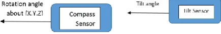
The robot also has two tilt sensors, one around the longitudinal axis of the robot and the other around the transversal axis and its component is shown in Fig.12.
The compass gives the angular deviation around the axes of three coordinates and their component is shown in Fig.12.
Fig. 12. compass and Tilt sensors component
The robot needs four joysticks to drive its parts, and the joystick is a passive device. Fig.13 shows the component of the joystick.
Fig. 13. joystick and camera components
The robot has two cameras, which are also inefficient devices. Fig.14 shows their component.
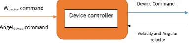
B. Low level control system
Fig. 15. device controller component
C. High Level Control system
This level has the following components:
• Management part of the robot component: There are three components to manage the robot parts, which control the movement of the platform, arm and grip, which are three components shown in Fig.16.
Fig. 16. Management part of the robot component
Auto-Manual switch component: This level contains three switches. It specifies the mode of operation (manual or automatic) based on Robot management level order and the fig.17 shows the Auto-Manual Switch component.
Fig. 17. Auto-Manual Switch component
Kinematic transformer component (KT): There is one KT and this component is shown in fig.18.
Fig. 18. Kinematic transformer component
D. Robot management level
This level has the following components:
Main tasks implementation component: contains the main tasks of the robot parts are:
1. Rotate the first arm. 2. Rotate the second arm. 3. .
4. Move the arm upwards according to the Y-axis. 5. Rotate the grip.
6. Open, close the grip.
7. Move the right part of the platform. 8. Move the left part of the platform.
It perform tasks based on a specific sequence sent from the Level of supervisor and can perform more than one task at a time. Fig.19 shows the robot management component.
Fig. 19. Main tasks implementation component
Monitoring of external sensors component: monitors the sensors of the distance on the base and the grip and warns the top level in case of approaching the obstacle to take the necessary actions to protect the robot. Fig.20 shows the monitoring of external sensors component.
Fig. 20. Monitoring of external sensors component
Robot stability control component: monitors the stability of the robot and alerts the Level of supervisor in taking the necessary actions to protect the robot. It receives information from KT and tilt sensors. As show in Fig.21.
Fig. 21. Robot stability control component
E. Supervisor Level
Composed of the following components:
Identify obstacles component: This component generates a sequence of processes that are executed on sequence or parallel, and is intended to determine the height of the obstacle or the hole width, send it to the main mission
implementation component and monitor the
information to the brain of the supervisory control component. Fig.22 shows the identify obstacles component.
Fig. 22. Identify obstacles component
Overcome obstacles component: After identifying the form, dimensions, and way to overcome the obstacle, this component generates a series of serial or parallel operations that are sent to the Main mission implementation component. Fig.23 shows the overcome obstacles component.
Fig. 23. Overcome obstacles component
Robot safety system component: receives
information from the monitoring of external sensors component, the robot stability control component and KT. It also receives the information from the monitoring of external sensors component and sends warnings to the brain of the supervisory control component with recommendations for robot protection. Fig.24 shows this component.
Fig. 24. Robot safety system component
Plant system host component: He communicates with the user, and asks him to determine the type of obstacle, sends him the necessary information about the state of the robot and alerts, and receives orders from him; it sends them to the brain of the supervisory control component. Fig.25 shows this component.
Fig. 25. Plant system host component
The brain of the supervisory control Component: Responsible for leading the other components of supervisor and coordination between them. It also receives orders from the user and sends requests, information and warnings through the plant system host component. It also coordinates between the identify obstacles component and overcome obstacles component to determine the possibility of overcoming the obstacle and the best way to overcome it. Information on the robot and the external environment is obtained from Low level control system and sensors. It also receives warnings from the robot safety system component and takes the necessary steps. Fig.26 shows this component.
Fig. 26. The brain of the supervisory control Component
F. Architectural Model
61 VI. MECHANICAL SYSTEM MODELLING
The 3D mechanical design assembly is developed with CATIA® software, and is exported to MSC ADAMS® to analyse the mechanical design to perform motion simulations to study the robot’s enhanced mobility characteristics through animations of different possible tasks that require various locomotion and manipulation capabilities [20]. Then, an ADAMS®-based mechanical system model can be obtained, using the following procedure:
1. Setting parameters: such as the gravitational acceleration, material properties, etc.
2. Adding constraints, driving moments and loading. Through constraints, the components are associated with each other and the relative motion is limited [21].
3. For each task, finding the sequence of movements necessary to complete the task.
4. Determine the torque required to implement the motion with the fixed speed angle, and determine the transfer gears and chains ratios.
5. Creation of state variables in model ADAMS® and export state variables of dynamic model to MATLAB-Simulink®, where the state variables are the key links of the internal information inflow and outflow in the ADAMS® model.
6. Establishing interfaces: The principle connection of the co-simulation is the digital signals, which are produced in one step in ADAMS® and SIMULINK®, are respectively transferred through interfaces. This process continues until the simulation ends [22].
7.
Simulation modelling of virtual prototype. The control scheme in SIMULINK® uses The ADAMS® model.A. ADAMS® –Based Mechanical System Modelling and
the results
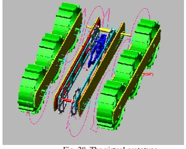
By following the steps described in the last section, we get in ADAMS® a virtual prototype (Fig.28).
Fig. 28. The virtual prototype.
B. Building the interface between ADAMS® and
MATLAB-SIMULINK®
The model built in ADAMS®, as a sub-system; need to be imported into MATLAB-Simulink® , where
interface. Second, define 15 system variables which are needed in co-simulation, there are 6 inputs systems variables: the angular velocity of the motors, and 18 output variables (Fig.29).
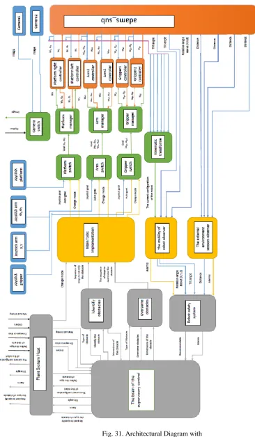
Fig. 29. The input/output of model in ADAMS®
Then connect the structure (Fig(27)) with the virtual prototype in ADAMS®, We get the following structure (Fig(31)).
VII.CONCLUSION
The development of enterprise distributed systems increasingly involves more integration of existing software. This paper presented a practical way to build a general model of multilevel control of a complex robot in MATLAB-Simulink®, it splits the structure into five levels so that each level contains components. It also shows the communication between the control structure and the mechanical model in ADAMS® environment, while permits the so true whole system modeling, and testing the mechanical response to orders come from the control levels, supervisor command. This technique made the simulation results more accurate and increases the design reliability. Debugging of virtual prototype model instead of physical mechanical model is more cost and time effective which improves efficiency of electromechanical system. Finally, this structure was applied to simulate a complex practical system, which is the Wheeled Hybrid Mobile Robot. In future, we will use petri net to implement correctly the multilevel control structure on the prototype showed in Fig(30).
REFERENCES
[1] Xiangyang Zhou, Beilei Zhao and Guohao Gong. Control Parameters Optimization Based on Co-Simulation of a Mechatronic System for an UA-Based Two-Axis Inertially Stabilized Platform. Sensors 2015. [2] David ThomasHamilton and Alessandro Tesini, An integrated
architecture for the ITER RH control system,Fusion Engineering and Design Volume 87, Issue 9, September 2012, Pages 1611-1615 [3] Debjyoti Bera, Kees M. van Hee and Jan Martin van der Werf,
Designing Weakly Terminating ROS Systems, in Application and Theory of Petri nets (The 33rd International Conference, Petri Nets 2012, Hamburg, Germany, Newcastle, June 25-29, 2012. Proceedings), vol. 7347, pages: 328-347,
[4] Lecture Notes in Computer Science, Berlin: Springer, 2012. [5] EJB. Available: http://java.sun.com.
[6] .NET. Available: http://www.microsoft.com/net/
[7] OMG, “Common Object Request Broker Architecture (CORBA/IIOP),” formal/2008-01-08, 2008.
[8] OMG, “Robotic Technology Component Specification,” formal/08-04-04, 2008.
[9] Developers-Aware 2.0 Robot Intelligence Software. Available: http://www.irobot.com/gi/developers/Aware
[10] J. Jackson, “Microsoft Robotics Studio: A Technical Introduction,” IEEE Robot. Autom. Mag., vol. 14, no. 4, 2007, pp. 82-87.
[11] C. Côté et al., “Robotic Software Integration Using MARIE,” Int.J. Advanced Robot. Syst., vol. 3, no. 1, 2006, pp. 55-60.
[12] H. Bruyninckx. Open RObot COntrol Software.http://www.orocos.org/, 2001.
[13] N. Ando et al., “RTMiddleware: Distributed Component Middleware for RT (Robot Technology),” IEEE/RSJ Int. Conf. Robots and Intelligent Systems, 2005, pp. 3555-3560.
[14] M. Quigley, K. Conley, B. P. Gerkey, J. Faust, T. Foote, J. Leibs, R. Wheeler, and A. Y. Ng. Ros: an open-source robot operating system. In Proceedings of the Workshop on Open Source Software held at the International Conference on Robotics and Automation (ICRA)., 2009 [15] Korean Institute for Advanced Intelligent Systems. OPRoS.
http://opros.or.kr/.
[16] Mallet, C. Pasteur, M. Herrb, S . Lemaignan, and F. Ingrand. GenoM3: Building middleware-independent robotic components. In IEEE Int. Conf. Robotics and Automation, pages 4627-4632, 2010.
[17] M.E. Munich, J. Ostrowski, and P. Pirjanian, “ERSP: A Software Platform and Architecture for the Service Robotics Industry,” IEEE/RSJ Int. Conf. Intelligent Robots Systems, 2005, pp. 460- 467.
[18] J.C. Baillie, “URBI: Towards a Universal Robotic Body Interface,” The 4th IEEE/RAS Int. Conf. Humanoid Robots, vol. 1, 2004, pp. 33-51. [19] K. Konolige “Saphira Robot Control Architecture,” SRI Int., 2002. [20] Developers-Aware 2.0 Robot Intelligence Software. Available:
http://www.irobot.com/gi/developers/Aware/
[21] Goldenberg, A. A., and Lin, J., 2005, “Variable Configuration Articulated Tracked Vehicle,” U.S. Patent No. 11/196,486.
[22] Brezina, T.; Hadas, Z.; Vetiska, J. Using of co-simulation ADAMS®-SIMULINK® for development of mechatronic systems. In Proceedings of the 14th International Symposium, on MECHATRONIKA, Trencianske Teplice, Slovakia, 1–3 June 2011; pp. 59–64.
[23] Zong, X.Y. and Y.Y. Li, 2005. Control simulation of robot arm based on ADAMS® and MATLAB®. Microcomput. Informat., 35: 29-30. [24] Florian Mösch. ORCA – Towards an Organic Robotic Control
Architecture. 1st International Workshop on Self-Organizing Systems September 18 - 20, 2006.
[25] Azamat Shakhimardanov, Jan Paulus, Nico Hochgeschwender, Michael Reckhaus and Gerhard K. Kraetzschmar. Best Practice Assessment of Software Technologies for Robotics. Bonn-Rhein-Sieg University (BRSU).
Salem Farah was born in Damascus, Syria, in 1974.He received the B.Sc. in mechatronics systems engineering from the Higher Institute for Applied Sciences and Technology (HIAST), Syria, in 1999, and the M.Sc. in control from KAU Kazan, Russia in 2011. He is currently pursuing the Ph.D. degree in control and Robotic at HIAST.
Ziad Dayoub was born in Damascus, Syria, in 1969. He received the B.Sc. in Mechanical engineering from Damascus University, Syria; He received the M.Sc. in Dynamics and strength of the elements of flight vehicles from The University of Bauman University, Russia, in 2001, and the Ph.D. degree in Dynamics of wheeled vehicles systems from Bauman University, Russia in 2006. He is currently a researcher in the Mechatronics Department at HIAST
![Fig. 1. Modular Decomposition of the ITER RH System [2]](https://thumb-us.123doks.com/thumbv2/123dok_us/1352405.1643849/1.595.328.550.530.674/fig-modular-decomposition-iter-rh.webp)
![Fig. 3. Organic Robot Control Architecture ORCA [24]](https://thumb-us.123doks.com/thumbv2/123dok_us/1352405.1643849/2.595.58.268.241.411/fig-organic-robot-control-architecture-orca.webp)