International Journal of Engineering & Technology IJET-IJENS Vol:09 No:10 83
Abstract ─ The flow over sharp-edged wings is almost always separated. The control of separated flows is possible and benefits can be achieved but only in a time average sense. A new design of an actuator was designed and tested which can achieve a wide range velocity of without frequency dependence, is free of oscillating components as well as free of secondary frequencies and therefore can be scaled up easily, unlike a traditional synthetic jet. The actuator can achieve a considerable amount of jet vectoring, thus aligning the disturbance with the leading edge shear layer. Results indicate that unsteady mini-jet actuation is an effective actuation device capable of increasing the lift in the stall region of the airfoil. Moreover, pressure measurements showed that two parameters could be altered to maximize the lift. The momentum coefficient needed a minimum value to exert influence and the actuating frequency need not be at exact the natural shedding frequency to improve the lift and can be operated at harmonics of the natural shedding frequency and obtain improvements.
Index Term ─ Separated Flow, Flow Control, Aerodynamics and Airfoil.
I. INTRODUCTION
In recent years there has been an increased interest in the flow control field, especially in aerodynamics, with the purpose of increasing lift and decreasing drag of airfoils. Wings suffer from flow separation at high angles of attack due to viscous effects, which in turn causes a major decrease in lift and increase in drag. This occurs to all types of airfoils, but especially to sharp edge wings. These types of wings are used on supersonic transports as well as in stealth technology due to the fact that flat surfaces and sharp edges help reduce the radar signature of the airplane by reflecting the radar signals away from the radar, while also reducing the wave drag due to the shock wave that otherwise would be detached if round edge airfoils were used. The problems with these types of wing geometries are that they need long runways and require a lot of power for takeoff and landing since at subsonic flight the lift for these airfoils is reduced as well advanced control systems and highly skilled pilots to maintain a safe degree of maneuverability.
Sharp edge airfoils suffer from separation even at low angles of attack such as 8°, because the flow cannot negotiate the sharp turn at the leading edge. As the flow separates, the airfoil behaves as a bluff body. Due to this separation, a reduction in lift will be experienced by the airfoil due to the fact that the airflow on the suction side of the airfoil is
separated and vortex shedding starts. The interest in this study is to try to control separated flow, not flow separation. With the implementation of flow control techniques, improvements in the lift coefficient can be obtained in a time-averaged sense. This is achieved by controlling the vortex-shedding phenomenon that in turn will improve a mixing enhancement of high momentum flow from the free stream with low momentum flow in the separated region. This mechanism is known as vortex lift.
II. THEORETICAL ASPECTS OF FLOW
SEPERATION
As stated before, the purpose of this research is to control separated flow and not flow separation. It is important to make this distinction, since the former refers to the effort of working along with a flow field that has already experienced boundary layer separation from a wall while the latter tries to prevent or delay separation, or reattach the flow field. Fiedler et al(1998) classified flow separation and possible techniques to address their situation as shown in Fig. 1.
Viscous flow theory predicts that a boundary layer forms on a wall due to viscosity forces where there is going to be a substantial variation of the velocity across the streamlines. It also states that a flow will separate in the presence of an adverse pressure gradient. For sharp edge airfoils, separation will always be fixed at the sharp leading edge since separation will occur at sharp corners due to the adverse pressure gradient. Sharp edge airfoils will suffer from massive separation at around eight degrees angle of attack.
When the flow separates from the wall, the boundary layer theory no longer holds since a shear layer will be formed. Vortices will be formed and they will be shed from the separation points located at the leading and trailing edges in an alternate way. These vortices are energized by the interaction of each other so the ones that are shed from the leading edge are in a disadvantage since these leading edge vortices are very weak to accomplish formation (Roshko 1967) so they may form or not until they reach the wake. This research will try to accomplish the enhancement of the leading edge vortices to see if they roll over the suction side surface thus obtaining a lower pressure and increasing the lift. We need to lay out the physical mechanism of the production, shedding, capture and enhancement of these vortices at post-stall angles of attack. Wu et al (1991) summarizes these four steps of the physics as vortex layer instability-receptivity- resonance.
Experimental Study of Separated Flow Control
Over a Sharp-Edged Arc Airfoil
Mohammad Mashud, Md. Mahfuz Sarwar, Md. Abdul Ghani Mollah and Md. Farhad Hossain Department of Mechanical Engineering
Khulna University of Engineering & Technology (KUET) Khulna-9203, Bangladesh
Fig. 1. Classification of flow field separation and flow management techniques
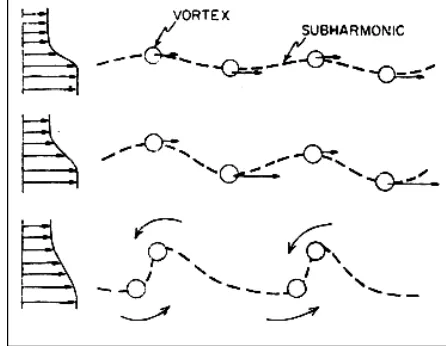
When flow separates, the result is the continuous shedding of a free shear layer. This shear layer, a vortex layer in itself, is unstable to small perturbations (Kelvin- Helmholtz instabilities) and the instabilities will cause a vortex merging. The upstream layer instability induces stronger and coherent vortex merging downstream (Ho et al 1984) as sketched in Fig.2 . This encouragement is repeated thus doubling the size of these global instabilities each time. This interaction of the shear layer with itself is called a feedback mechanism.
It is important not only to understand the vortex layer evolution but its resonance as well. Resonance can best be described from oscillation theory. If a forcing term matches one of the fundamental modes of a linear oscillator then a magnified response will develop and the oscillator’s response will be amplified. Even some higher order modes might be amplified and manage somewhat this vortex flow.
Resonance needs the interaction of two periodic events that are in phase with frequencies that are integer multiples of each other. For this to occur a periodic flow feature and a feedback mechanism are needed so the disturbance enables the layer to interact with itself. The purpose is to trigger a self-organizing mechanism of relative small energy input so that the energy is drawn from the random fluctuating motion or vorticity concentration such as the ones produced by mechanical flaps and unsteady jets. Here the vortex shedding frequency is locked and also must of the energy is converted into the vortex itself. The problem vortex-vortex interaction is that the frequency range is usually up to 100 Hz. A good feature is that the forcing frequency does not need to be the optimal resonance frequency to achieve a significant effect.
Fig. 2. Vortex induction by instabilities in a free shear layer.
III. METHODOLOGY
So far, efforts have been reported to control the flow separation over airfoils with rounded leading edges, while here we report on the control of separated flow over sharp- edged airfoils. These techniques are equally applicable for the control of separated flows over rounded airfoils. There are two important differences between the actuator requirements for the two cases. First, the location of the actuators for the control of separation over rounded airfoils is not critical since the flow is still receptive to an external disturbance, whereas for the control of separated flow the actuation must interact with the free-shear layer. This fact dictates that the actuator of a sharp-edged wing must be as close as possible to the sharp edge, which leads to the second important difference. The direction of the actuation disturbance must be adjusted to lead the disturbance as much as possible in the direction of the free shear layer. Two additional important parameters are the momentum coefficient Cµ and frequency of the actuation. Different angles of attack and free stream velocities will require a wide variety of possible combinations. Been able to independently control both is a great challenge. These requirements may appear too stringent for the sharp-edged airfoils but on the other hand, they may provide some opportunities for robust control with minimal energy input. It is possible that free shear layers would be more receptive to disturbances right at their initiation that is as close as possible to the sharp leading edge. Another similar situation is the control of asymmetric wakes over pointed bodies of revolution at incidence. In this case, minute disturbances very close to the apex can feed into the global instability of the flow and lead to very large wake asymmetries as shown by Zilliac et al (1990) and Zeiger et al (1997).
It is important to note that periodic blowing is more effective than a steady jet due to resonance. For blowing, the momentum coefficient is define by McCormick (2000) as
(
)
(
)
∞=
22
cU
hu
C
jetρ
ρ
International Journal of Engineering & Technology IJET-IJENS Vol:09 No:10 85
where . ρ is the density of air and cancels out, h is the slot height, c is the chord of the airfoil and u and U are the respective velocities of the jet and the free stream. This is the relation of the input energy to kinetic energy of the free stream and is suggested in Wu et al (1997) that it should to be at least 1%.
The disturbance frequency likely to be amplify the most is given, using linear stability theory, by the Strouhal number
∞
×
×
=
U
Sin
c
f
St
shedding(
α
)
where fshedding is the sheddingfrequency; c is the airfoil chord, α is the angle of attack and
∞
U
is the free stream velocity. We are going to assume a value of St=0.2 for this research as is thoroughly accepted in literature. Seifert et al (1999) gives tvhe actuation frequency, related to the shedding frequency, the reducednon-dimensional frequency
shedding actuation
f
f
F
+=
. He suggeststhat this reduced frequency to be 0.4< F + <2 since it seems that harmonics play a role in the dynamic process.
IV. MODEL CONSTRUCTION
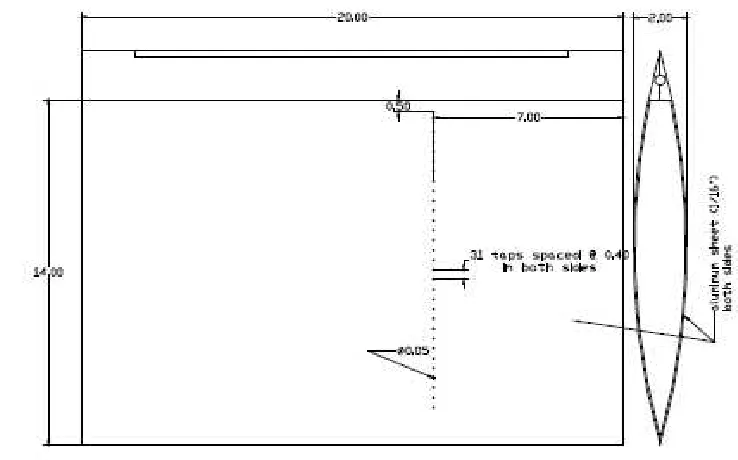
The model used for this phase is a symmetric circular arc 12 ½ percent chord thickness airfoil. The chord length is 34 cm with a resulting maximum thickness of 3.2 cm. Its span is 18 cm. It was built in two separate phases: the jet actuator and leading edge and the body of the airfoil.
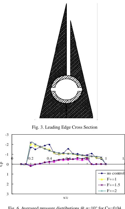
The design of the jet mechanism took into account the desire of having it as close as possible to the leading edge of the airfoil. The leading edge part of the wing is essentially a wedge prism as shown in Fig. 3. The actuation mechanism consists of two concentric cylindrical surfaces as shown in Fig. 4. The inner cylinder is a 1.4 cm-diameter inner brass tube that contains eight 0.3 cm wide slots and 7.7 cm long with 0.3 cm separation between them. The inner cylinder rotates about a fixed axis inside a fixed outer cylindrical surface created by the machined wedge. The inner cylinder is a brass tube, free to rotate on three bushings.
One bushing was machined to fit snugly between the brass tubing and the machined leading edge at mid-span. This was done to eliminate possible warping of the tube during rotation.
The body was made entirely of aluminum and consists of three holding ribs and two 1/32 sheets that serve as the skin. The ribs have holes through them that provide access to the inside.
Each side has 34 pressure taps aligned and located at 177.8 mm (7 in) from starboard side as can be seen in Fig. 2-5. The taps start at 63.5 mm (2 ½ “) from the leading edge and are spaced at 10.16 mm (0.4 in) along the arc. Copper tube tubing of 2 mm (0.05 in) o.d., 1.5 mm (0.033 in) i.d. and 6 mm (1/4 in) in length was inserted in each tap with tygon tubing R-3603 of 2 mm o.d. and 0.8 mm (1/32 in) i.d. connecting them to the pressure transducers.
To evaluate the capabilities of the actuator, the assembled leading edge actuator along with a rake of high-frequency-response Pitot tubes were mounted, as shown in Fig. 5. Endevco model 8510 pressure transducers were used as sensing elements inside the rake. The output of the pressure transducers was connected to a HP digital signal analyzer, which was used to measure jet frequencies. In addition, these were also connected to a simple PC-driven 12-bit data acquisition system. The rake was mounted on traversing scales so it could easily be displaced to obtain data at different locations relative to the slotted nozzle.
Fig. 3. Leading Edge Cross Section
-3
-2
-1
0
1
2
3
0 0.2 0.4 0.6 0.8 1 1.2
x/c
C
p
no control F+=1 F+=1.5 F+=2
Fig. 6. Averaged pressure distributions @ α=10° for Cµ=0.04
-3
-2
-1
0
1
2
3
0 0.2 0.4 0.6 0.8 1 1.2
x/c
C
p
no control F+=1 F+=1.5 F+=2
-3
-2
-1
0
1
2
3
0 0.2 0.4 0.6 0.8 1 1.2
x/c
C
p
no control F+=1 F+=1.5 F+=2
Fig. 8. Averaged pressure distributions @ α =15° for Cµ=0.0285 for susonic wind tunnel.
Fig. 4. Exploded View of Leading Edge and Flow Control Device
International Journal of Engineering & Technology IJET-IJENS Vol:09 No:10 87
V. EXPERIMENTAL SET-UP AND PROCEDURE
The experiments were conducted using 36×36×100 cm subsonic wind tunnel at Fluid-dynamics Laboratory, Department of Mechanical Engineering, Khulna University of Engineering & Technology.. A small sized model is appropriate to examine the aerodynamic characteristics for the experiments, due top the restriction of wind-tunnel size. The model was placed in the middle of the test section supported by a frame. The frame is constructed by four 5mm diameter threaded iron rod, bolts, a flat plate and two bars with angle measuring system. The four threaded rods placed the plate tightly inside the wind tunnel. This plate holds the two bars, and these bars hold the model tightly inside the wind tunnel. One bar has an extended part which is used to measure the angle of attack of the model.
For this purpose a digital manometer was placed outside of the wind tunnel test section. There were drilled holes vertically in every 1.5 cm distance of the model and vinyl tubes were placed in these holes. The vinyl tubes connected between the pressure tubes and the manometer. The model surface pressure varies according to the scale of the chord length, which is much larger than the boundary layer thickness. For three constant motor speeds of the wind tunnel, difference of the inside surface pressure of wind tunnel and the surface pressure of the model were measured. So finally the static surface pressure at different points on the surface of the model was obtained.
VI. RESULTS AND DISCUSSION
Present the averaged pressure distributions over the suction and the pressure side of the airfoil for two different Cµ values and three angles of attack in the subsonic wind tunnel. This setup had the problem that it suffered from solid blockage as defined by Pope et al (1999) since the model reduces the cross-sectional area of the tunnel, and as a result the air velocity around the model is increased. The model created a blockage of almost 21% when it was at 15° angle of attack. The results obtained in the subsonic tunnel cannot provide direct information on lift and drag of sharp-edge wings. But our aim here is to explore the effects of flow control by comparing data obtained with and without control. The blowing amplitude was sustained at a constant level and the Cµ was adjusted by changing the free-stream
velocity. The reduced frequency F+ was changed and set at 0, 1, 1.5 and 2.
The pressure distributions do not indicate a clear stall situation for 10° (Fig. 6) and ven 15° and actually suggests attached flow in the average. For Cµ=0.0285 at
α=15° Fig. 8) the control clearly increases the maximum suction. The suction strength is stronger on the leading edge part of the airfoil and it decreases towards the trailing edge. Unlike the other Cµ case that showed almost no improvement, here we observe a 15% drop in suction pressure. This difference suggests that the momentum coefficient Cµ should be at least greater than 1.5%. It also shows a small improvement when the actuator was operated at larger F+ than unity. This indicates that the harmonics of the natural frequency get excited and can contribute to the resonance effect. One
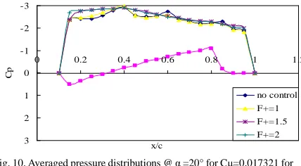
last observation from the second plot of each fig. is that at smaller free stream speed (12 m/s and larger Cµ) the pressure distributions on the suction side for 10° (Fig. 6), 15° (Fig. 8), 20° (Fig. 9) and somewhat for 25° seem to be chaotic when there is no control. When control is applied, the chaotic situation is reduced or eliminated. This change in the profiles suggests that the actuation mechanism helps organizing the flow field for this particular situation of blockage.
-3
-2
-1
0
1
2
0 0.2 0.4 0.6 0.8 1 1.2
x/c
C
p
no control F+=1 F+=1.5 F+=2
Fig. 9. Averaged pressure distributions @ α =20° for Cµ=0.012991 for subsonic wind tunnel
-3
-2
-1
0
1
2
3
0 0.2 0.4 0.6 0.8 1 1.2
x/c
C
p
no control
F+=1
F+=1.5
F+=2
Fig. 10. Averaged pressure distributions @ α =20° for Cµ=0.017321 for subsonic wind tunnel
Lift coefficients were calculated by integrating the pressures over the suction and pressure sides of the wing. The results are presented in Table I, for the three values of Cµ as well as no control. The benefit on the lift coefficient is large in the post stall area although it is reduced as is increased as seen in the last column, which is a comparison between the no control case and the control case with the highest Cµ. One of the reasons for this is that there were limitations in the actuating frequency. This suggests that even if it is not the natural frequency or one of its harmonics it is still possible to achieve some enhancement and increase the lift.
TABLE I
Lift Coefficient CL for conditions at Stability Tunnel A
O A
No Control
Cµ
=0.003 Cµ
=0.01 Cµ
=0.03
Increase in CL
3 0.4230 0.4105 0.4354 0.4458 5% 6 0.6420 0.6690 0.6277 0.6405 -0.23% 9 0.8410 0.8047 0.8048 0.8571 1.91% 12 0.5719 0.5905 0.6086 0.7344 28.41% 15 0.3881 0.3801 0.4131 0.5117 31.85% 18 0.3538 0.3424 0.3874 0.4395 24.22% 21 0.3618 0.3587 0.3884 0.4116 13.76%
Table II, which describes the Lift to Drag ratio for the same conditions. Here the increase is not as pronounced as it is for the Lift coefficient. This indicates that the Drag is increasing as well. The vortex decreases the pressure over the surface but the force obtained is normal to the surface. When the angle of attack is increased the component of the normal force in the direction of the drag is increased as well and the lift component is reduced. This situation could be addressed by keeping the vortex closer to the front of the airfoil and detaching it farther from the trailing edge as the angle of attack is increased.
TABLE II
Lift to Drag ratio for conditions at Stability Tunnel A
O A
No Contro
l
Cµ
=0.003 Cµ
=0.01 Cµ
=0.03
Increase in CL/CD
3 7.2284 7.9616 8.0982 8.1358 12.6% 6 9.3834 10.652 9.2264 9.3714 2.8% 9 7.5310 6.9529 7.1952 7.5868 0.74% 12 3.0834 3.3201 3.1975 3.8473 24.77% 15 2.1611 2.1575 2.1483 2.4982 15.60% 18 1.8374 1.8156 1.8567 1.9781 7.65% 21 1.6635 1.6381 1.6524 1.7168 3.2%
VII. CONCLUSION
The purpose of this research was to develop a flow control mechanism that could generate a pulsing jet along a slotted nozzle to increase the lift of circular-arc airfoils. A novel pulsing jet actuator was designed and constructed. One of the features of this device is that it can generate oscillating disturbances without any mechanical parts like an oscillating flap, which could be detrimental to the radar signature of an airplane. Another feature is that the efficiency of this actuator is practically independent of the frequency. The design proved that uniform and more powerful pulsing jets could be generated along the span of the airfoil. In addition, this actuator did not generate nonlinear interactions and therefore any secondary frequencies as synthetic jets tend to do. This means that the device is an excellent candidate for a robust flight actuator, where the required frequency is changing with aircraft speed and angle of attack. The location and geometry of the jet exit revealed that the asymmetry of the walls induces the formation of a starting vortex. This vortex provides a significant vectoring effect that guides the disturbance in the direction of the leading edge free shear layer.
Moreover, this vortex interacts with the leading edge shear layer, exciting its natural instabilities and thus forcing the shear layer to roll, forming a strong coherent vortex. Finally, we demonstrated for the first time, that unsteady blowing right at the leading edge of a sharp-edged circular arc airfoil allows the management of the separated flow, leading to averaged pressure distributions that correspond to higher lift. This was shown to be due to convecting vortices, as detected in the form of a low pressure traveling wave. Significant improvement was obtained in the lift coefficient for moderate to high angles of attack. But the effect
decreased as the angle of attack was further increased, possibly due to less effective interaction between the disturbance and the shear layer. The data obtained with unsteady blowing indicate that there is a minimum of energy needed in order to exert a proper disturbance to the shear layer. In addition, the research suggests that the harmonics of the natural shedding frequency can have even greater impact than the natural frequency. Finally, the actuating frequency did not have to match the natural frequency since resonance was still achieved when locked to higher actuating frequencies.
REFERENCES
[1] Abiven, C., Vlachos, P. P., “Super spatio-temporal resolution, digital PIV systemfor multi-phase flows with phase differentiation and simultaneous shape and size quantification”, Int. Mech. Eng. Congress, Nov. 17-22, 2002, New Orleans, LA,2002.
[2] Abiven, C., Vlachos P. P., Papadopoulos, G, “Comparative study
of established DPIV algorithms for planar velocity
measurements”, Int. Mech. Eng. Congress, Nov. 17-22, 2002, New Orleans, LA,2002.
[3] Amitay M, Smith B. L. and Glezer, “Aerodynamic flow control
using synthetic jet technology”, AIAA Paper 98-0208,1998. [4] Artana, G., D’Adamo, J., Léger, L., Moreau, E., Touchard, G.,
“Flow Control with Electrohydrodynamic Actuators” AIAA Journal
Vol. 40, pp. 1773-1779,2002.
[5] Cahill, J. F., Underwood, W.J., Nuber, R.J., Cheesman, G.A., “Aerodynamics forces on symmetrical circular-arc airfoils with plain leading-edge and plain trailing-edge flaps” NACA Report 1146,1953.
[6] Cattafesta, L.N, Garg, S., Shukla, D.“Development of
Piezoelectric Actuators for Active Flow Control”AIAA Journal Vol. 39, pp.1562-1568, 2001.
[7] Didden, N. “On the Formation of Vortex Rings: Rolling Up and
Productions of Circulation.” Z. Angew. Math.Phys. Vol 30, pp101-106,1979.
[8] ELD, 24” Flow Visualization Water Tunnel, Operating and
Maintenance Instructions,1984.
[9] Fiedler, H. E., “Control of Free Turbulent Shear Flows”. In Flow
Control: Fundamentals and Practices (ed. Gad-el-Hak, M., Pollard, A., Bonnet, J. P.), pp. 335-429, 1998.
[10] Gad-el-Hak , M., “Flow Control: the Future,” J. of Aircraft. Vol.
38, No. 3, pp. 402-418, 2001.
[11] Gilarranz, J. L., Rediniotis, O. K., “ Compact, High-Power
Synthetic Jet Actuators For Flow Separation Control,” AIAA Paper 2001-0737, 2001.
[12] Glezer, A. “The Formation of Vortex Rings”. Phys. Fluids, Vol