DOI:
http://dx.doi.org/10.21172/1.84.24
e-ISSN:2278-621X
Inside Flow Characterization of a Nozzle: Numerical
Approach
Mohammad Ilias Inam
1, Mohammad Mashud
21. INTRODUCTION
A divergent duct can be used when it becomes necessary to expand a fluid to increase the pressure and thereby decrease the velocity. Our current investigation aimed at analyzing the flow patterns and the variation of velocity inside the divergent duct along the centerline region. Study of the flow characteristics inside the diverging duct is of great importance if it is necessary to increase the velocity along core flow region, as flow is always affected to some extent by the length, inlet diameter, outlet diameter and other boundary conditions. If it is possible to increase the velocity along the centerline region by flowing fluid through a divergent duct, it can be used as a wind accelerator for a wind turbine. Because if it is possible to increase the velocity of the approaching wind to a wind turbine the power generated by turbine could be increased as wind power generation is proportional to the wind speed cubed. By placing a turbine into a divergent duct can accelerate the approaching wind velocity along the center line and can increase the power output.
In the case of internal duct flow the boundary layer thickness is considerably affected by the pressure gradient in the direction of flow. When a flat plate placed in a stream of velocity, the pressure may assumed to be uniform i.e. the pressure gradient is zero. But in the case of divergent flow i.e. the flow through diverging duct the pressure gradient is positive; the fluid in the boundary layer is further decelerated and hence assists in thickening of the boundary layer. The adverse pressure gradient plus the boundary shear decreases the momentum in the boundary layer and if they both act over a sufficient distance they cause the fluid in the boundary layer to come rest i.e. the retarded fluid particles, cannot, in general penetrate too far into the region of increased pressure owing to their small kinetic energy. Thus, the boundary layer is deflected sideways from the boundary, separates from it and moves into the main stream. This phenomenon
1 Department of Mechanical Engineering, Khulna University of Engineering & Technology, Khulna, Bangladesh.
2 Department of Mechanical Engineering, Khulna University of Engineering & Technology, Khulna, Bangladesh.
ABSTRACT: Flow characteristics were investigated theoretically and numerically, inside a diverging duct through which a periodically fully developed flow of fluid is passed as working fluid. The governing differential equations along with boundary conditions were solved by finite difference method. The discritized equations with proper boundary conditions of numerical solutions were sought by obtaining Leibmann’s Successive under Relaxation (SUR) method. It has been done on the basis of stream function and vorticity formula of the two dimensional Navier-Stoke’s equation and continuity equation for all nodes. Computations were performed for different values of the Reynolds Number and the geometric parameters. If the divergence angle is sufficiently high and for high Reynolds number the flow become unsteady. The current study is ended only for steady laminar flow. Numerical results obtained were analyzed for the effectiveness of different values of duct length and outlet diameter for a fixed inlet diameter.
is called separation [1]. Separation of the boundary layer greatly affects the flow as a whole. The separation of fluid in a divergent channel depends upon the angle of divergence, Reynolds number and inlet velocity [2]. The separation of the flowing fluid is from the boundary first occurs at a point where the velocity gradient become zero, this point is known as separation point. On downstream of the separation point, a farther retardation of the fluid close the boundary can even have reverse or back flow near to the boundary. At the edge of the separated boundary layer, the velocities change direction. As a result of the reverse flow large irregular eddies are formed. The flow in eddies causes circulation of fluid [1], which produces, a line of vortices (known as a vortex sheet) [3]. This happens because fluid to either side is moving in the opposite direction. The recirculation in the upper boundary is reversed with respect to recirculation in the lower boundary. These recirculations in upper and lower boundary produce a negative pressure along the duct surface. This negative pressure causes increase in mass flow rate, which causes increase in velocity along the centerline region of the main stream flow. Increasing the angle of the divergence increases the boundary layer separation, which produce more vortices [3]. This results more increase in velocity along the centerline. It could seen from the analysis that the recirculation length increased with increase of Reynolds number, and for high Reynolds number the recirculation region extend to the inlet and the flow became complex.
Experimental investigations were carried out by Mohammad Mashud, Md. Mahfuz Sarwar and Md. Nafiur Rahman [4]; they developed a diffuser-type structure that is capable of collecting and accelerating the approaching wind. They devised a diffuser shroud with a brim that is able to increase the wind speed of approaching wind substantially by utilizing various flow characteristics (e.g., the generation of a very-low-pressure region by vortex formation, flow entrainment by vortices and so on) of the inner or peripheral flows of a diffuser shroud equipped with a brim. They showed that the velocity could be increased 1.6 to 2.4 times that of inlet by directing the air through a divergent duct, with attaching a brim of proper height to the outer periphery at the duct exit. In this investigation we consider only a diverging duct without brim or shroud.
The present study, however deals with systematically investigate the laminar flow through diverging duct for variation of parameters affecting the flow field. This study will enable the creation of a knowledge base for more effective and efficient design of diverging duct encountered in engineering applications. Such a knowledge base will also be helpful in avoiding costly experimentation to study the performance of diverging duct.
2. GOVERNING EQUATION
We considered a divergent channel of length L, inlet diameter d and outlet diameter D. A parabolic velocity profile is used at the inlet. Fig. 2.1 shows the geometry of the flow domain. The flow is considered to be two dimensional, steady state, incompressible, laminar and the physical properties are assumed to be constant through the divergent channel. The body force is neglected (FX&FY) here. The equation of motion for incompressible flow with constant transport properties, namely the Navier-stoke’s equation and the continuity equation are used here as the governing equation. The governing equations in the non-dimensional form are-
Continuity equation
i
Y
V
X
U
...
...
...
...
...
...
...
0
* *
Navier-Stokes equation
ii Y U X U X Y U V X U U ... Re 1 2 * 2 2 * 2 * * * * *
iii Y V X V Y Y V V X V U ... Re 1 2 * 2 2 * 2 * * * * * ;
d
x
X
;
d
y
Y
;
max *
u
u
U
;
max *
u
v
V
And Reynolds number is defined as
d
u
maxRe
The general boundary conditions in the flow domain are-
Boundary Condition for Inlet section:
Applying fully developed parabolic inlet profile,
4
4
(
2)
22
max
*
Y
Y
d
y
d
y
u
u
U
In normal form,
u
4
y
(
1
y
)
Stream function is obtained2 3 0
3
4
2
y
y
Here
0= Constant The vorticity at inlet section,2
4
2
1
2
y
y
y
u
(at the inlet v=0)Boundary Condition for outlet section: Assuming fully developed flow conditions,
0
0
x
v
x
u
0
0
x
x
At the Bottom Boundary:
We know that the velocity components
y
u
andx
v
Applying no-slip conditions,
u=0 and v=0
Stream function
c
,
Assume c=constant At The Top Boundary:3 NUMERICAL METHODOLOGY
The governing equations along with boundary conditions are solved using a numerical code written in FORTRAN language to get stream function, vorticity and velocities at every nodal point. Finite difference method is used to descritised the equations. The conventional Gauss-Seidal method is used for iteration technique to solve the equations along with boundary conditions. The successive under relaxation (SUR) method is employed to accelerate the rate of convergence after each iteration. The inlet diameter and inlet velocity was fixed. The flow domain is solved for length 2.0 and 3.0 and the outer diameters vary from 1.2 to 3.0 with an interval of 0.2 for both of the length. The effect of Reynolds number on the flow field was studied for Reynolds numbers 200, 400, 600, 800, 1000, and 1200. But for both length 2.0 and 3.0, when outer diameter greater than 1.4 for Reynolds number greater than 400 the flow became complex and we are not analyzed that kind of flow.
4 RESULTS AND DISCUSSION
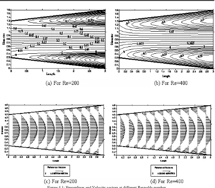
The results obtained by numerical (finite difference method) solution of the Navier-Stokes and continuity equations for expanding axis symmetric laminar flow is presented. A typical geometry for this study and boundary conditions have already been discussed above. The parameters affecting the performance of a diverging duct are the Reynolds numbers, angles of expansion (D/d) and lengths. The results presented here show the effect of varying Reynolds number on the flow domain for constant geometrical properties; for a length of 3.0, inlet diameter 1.0 and outlet diameter 1.60. It is found that the centerline velocities of the parabolic profiles are almost 1.08 to 1.99 times of the inlet for different Reynolds numbers at the outlet. Figure 4.1(a) and 4.1(b) shows the streamline plots for two different values of Reynolds number. It can be seen that there are two different flow regions, namely the core flow region and the recirculation region. The recirculation region is indicated by the separating streamlines. The recirculating zone increases in size as Re increases. The recirculation region is the result of the pressure gradients normal to the stream lines. The effect of increasing Reynolds number strengthens and widens the recirculating zone and the overall flow intensifies. Dead flow reserve regions are created at the vicinity of the boundaries.
The analysis of the flow field in the preceding sections can be better envisioned by the velocity vector field provided in Figure 4.1(c) and 4.1(d). A greater shaft length of the arrows near the wall and along the centerline near the outlet gives the indication of higher velocities in that region. It is well evidenced from the velocity vector field that at higher Reynolds number and greater angles of expansion significant recirculating bubbles are formed near boundaries. These bubbles are produced by a significant reduction in fluid momentum and adverse pressure gradient caused by area expansion.
D
d
L
Direction
of fluid
flow
Figure 4.1: Streamlines and Velocity vectors at different Reynolds number
The axial velocity distributions through the divergent duct for varying Reynolds number are plotted in Figure 4.2. The velocity profile at the entrance to the channel is parabolic with a maximum axial velocity of unity in accordance to the boundary condition. Figure 4.2 show that the peak of the horizontal velocity component increases and its location shifts toward right with the increasing Reynolds number. Near the wall, a large velocity area with negative axial velocity develops which indicates the existence of significantly large recirculation region. Near the outlet, for Reynolds number ranging from 200 to 400, the cross-sectional maximal axial velocities are at least 1.08 times larger than the entrance.
0 0.1 0.2 0.3 0.4 0.5 0.6 0.7 0.8 0.9 1 1.1 1.2 1.3 1.4 1.5 1.6
-2.0 -1.6 -1.2 -0.8 -0.4 0.0 0.4 0.8 1.2 1.6 2.0
Velocity Component, U/Umax
D
ia
m
e
te
r
X=1.6 Re=200 X=1.6 Re=400
Figure 4.2: Velocity profile at channel of Length=3.0 of Outer Diameter=1.6
0.0 0.2 0.4 0.6 0.8 1.0 1.2 1.4 1.6 1.8 2.0
0.0 0.2 0.4 0.6 0.8 1.0 1.2 1.4 1.6 1.8 2.0 2.2 2.4 2.6 2.8 3.0
Distance, X/d
U
/U
m
a
x
a
t
C
e
n
te
rl
in
e
Re=200 Re=400
Figure 4.3: Variation of centerline velocity at channel of Length=3.0 of Outer Diameter=1.6
5 CONCLUSION
The present numerical study throws some light on flow inside a diverging duct. The extent of recirculation near the boundary helps in increasing the velocity in the centerline region. The study also reveals the effect of change in Reynolds number and geometrical parameters on flow domain. This kind of study will definitely help to design diverging duct for flow accelerator like within the wind turbine.
L Length of the domain ω Vorticity
d Inlet diameter of the domain ω* Dimensionless Vorticity
D Outlet diameter of the domain Ψ Stream function
o Initial value of Stream function Density of fluid
*
Dimensionless Stream function
u
Free stream velocity μ Dynamic viscosity of fluid υ Kinematic viscosity of fluidRe Reynolds number =
d
u
u,v Velocity components
X,Y Dimensionless x and y co-ordinate
U*,V* Dimensionless velocity components
7 REFERENCE
[1] Modi, P. N.; Seth, S. M.;“Hydraulics And Fluid mechanics Including Hydraulic Machines” Fourteenth Edition, 2002, pp. .238, 239, 518, 519, 531,930.
[2] Cockrell, D.J., and Markland, E., 1963, “A Review of Incompressible Diffuser Flow,”Aircraft Engineering, October, pp. 286-292.
[3] Douglas J F, Gasiorek J. M. and Swaffield J. A., ”Fluid Mechanics”, Longman publishers, pp 327-332.
[4] Mashud, Mohammad, Sarwar, Md. Mahfuz and Rahman, Md. Nafiur, “Development of a High-Performance Wind Turbine with a Diffuser”, Paper ID 146, 12th Annual Paper Meet, February, 2008, Dhaka.