Statistical Review of Design Guidelines for Effective
Bond Length of FRP Laminates Externally Bonded to
Concrete
Fares Jnaid, Ph.D., P.E.,Assistant Professor of Civil Engineering, Gildart Haase School of Computer Sciences and Engineering, Fairleigh Dickinson University, 1000 River Road, Teaneck NJ 07666, USA.
315-456-9871 201 692 2130 [email protected]
Abstract-- Within the last three decades, the applications of externally bonded Fiber Reinforced Polymer (FRP) systems in the strengthening of concrete structures has been rapidly growing. Debonding between FRP laminates and concrete structures remains a major cause of system failure. Extensive studies have been conducted in order to estimate the effective bonding length of FRP sheets externally bonded to concrete. This paper presents a critical evaluation of 16 different equations gathered from various guidelines and researchers by comparing them to 51 experimental samples. In addition, this research proposes a new equation to compute the effective bonding length based upon the wide range of collected data.
Index Term-- Effective, Bond, Length, Concrete, FRP, Laminate Abbreviations: FRP: Fiber Reinforcement Polymer
INTRODUCTION
FRP systems have been universally adopted as an alternative to other strengthening techniques. Many applications such, as strengthening of bridges and buildings, use these systems. Being light weight and easy to install are just some of the advantages that FRP systems have over steel. Additionally, they are not susceptible to corrosion, which decreases the degree of bond deterioration between FRP materials and concrete. However, FRP is a brittle material, which means, they experience a sudden brittle mode without displaying any ductile warning. Bond between external FRP laminates and concrete surface is extremely important in order to allow a full transfer
of stresses between concrete and FRP, as well as, ensuring the development of a composite section.
EFFECTIVE BOND LENGTH
The effective bond length (Le) is the length over which the
majority of the bond stress is maintained [1]. In other words, Le
Fig. 1. Anchorable tensile stress related to anchoring length (after Niedermeier [6])
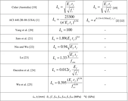
Table I
Different effective bond lengths as suggested by various guidelines/researchers (after Ouezdou et al. [24], expanded)
Code Formula Reference
FIB B14-Appendix A1 (Europe) [10]
ctm f f e
f
c
t
E
L
2
c
2
2
ctm f f e
f
t
E
L
2
[7]FIB B14-Appendix A2 (Europe) [10]
ctm ck f f e
f
f
t
E
c
L
244
.
1
2
c
̶ISIS Design Manual (Canada) [11] 0.58
)
(
25350
f f et
E
L
6.1340.58ln(Eftf)e
e
L
*[2] [12]CSA S806-02 (Canada) [13] 0.58
)
(
25350
f f et
E
L
6.1340.58ln(Eftf)e
e
L
*[2] [12]CS TR55 (UK) [14]
ctm f f e
f
t
E
L
0
.
7
ctm f f e
f
t
E
L
2
[7]Eurocode 8-3 (Europe) [15]
ctm f f e
f
t
E
L
4
ctm f f ef
t
E
L
4
[6]SIA 166 (Switzerland) [16]
ctH f f e
f
t
E
L
16
3
̶CNR-DT 200/04 (Italy) [17]
ctm f f e
f
t
E
L
2
ctm f f ef
t
E
L
2
Cidar (Australia) [18]
'
c f f e
f
t
E
L
'
c f f e
f
t
E
L
[19]ACI 440.2R-08 (USA) [1] 0.58
)
'
(
23300
f f e
t
E
n
L
6.1340.58ln(Eftf)e
e
L
[2] [12]Yang et al. [20]
L
e
100
̶Sato et al. [21]
L
e
1
.
89
(
E
ft
f)
0.4 ̶Niu and Wu [22]
L
e
0
.
94
E
ft
f ̶Lu [23]
ctm f f e
f
t
E
L
1
.
33
̶Ouezdou et al. [24]
'
012
.
0
c f f e
f
E
t
L
̶Wu et al. [25] 0.09
58 . 0
)
(
395
.
0
co f f e
f
t
E
L
̶Le, tf (mm) Ef , fc', fck, fco, fctH, ft, fctm (MPa) *Ef (GPa)
Recently, some studies suggest that when "peeling-off" occurs, the tensile strain of the FRP depend on a wide range of parameters, such as the properties of concrete and FRP laminates, crack spacing, and loading pattern. Therefore, the global strain limit may not be valid for all applications, resulting in a non-economical use of FRP, especially when strengthening large spans. The more accurate strain limitation models, based on extensive test data as well as analytical calculations, will be replacing the current models [10].
Experimental Studies
Different researchers performed different test setups in order to
investigate the effective bond length of externally bonded FRP
laminates. The collected experimental data from 9 different
researchers contain 51 test specimens. The performed test
setups consisted of single and double shear tests.
Table demonstrates the gathered data. Note: the mean tensile
strength values of concrete (fctm) in
Table are obtained from Table 3-1 in Eurocode 2 [25].
Table II
Experimental data performed by other researchers (after Ouezdou et al. [24], expanded)
Spec. Test FRP n fctm
(MPa)
ft
(MPa) f'c(MPa) Ec(GPa)
Ef
(GPa) tf(mm) Le(mm)
Sato et al. [26] - Double CFRP 1 3.356 - 37.6 25.5 236 0.115 45.2
Bizindavyi and Neale [27]
- Single GFRP 1 3.65 472 42.5 33.5 29.2 1 75
- Single GFRP 1 3.65 472 42.5 33.5 29.2 2 100
- Single CFRP 1 3.65 1014 42.5 33.5 75.7 0.33 55
- Single CFRP 1 3.65 1014 42.5 33.5 75.7 0.66 70
De Lorenzis et al. [28] - Single CFRP 1 3.92 4272 47.3 - 227 0.16 93
Pellegrino et al. [29]
S1C1a Single CFRP 1 4.46 3430 63 - 230 0.165 72.5
S1C5c Single CFRP 1 4.32 3430 58 - 390 0.165 87.5
S2C1a Single CFRP 2 4.46 3430 63 - 230 0.33 77.5
S2C1b Single CFRP 2 4.32 3430 58 - 230 0.33 85
S2C1c Single CFRP 2 4.32 3430 58 - 230 0.33 77.5
S3C1a Single CFRP 3 4.46 3430 63 - 230 0.495 106
S3C1b Single CFRP 3 4.32 3430 58 - 230 0.495 108
S3C1c Single CFRP 3 4.32 3430 58 - 230 0.495 107.5
S2C5a Single CFRP 2 4.46 3430 63 - 390 0.33 107.5
S2C5b Single CFRP 2 4.32 3430 58 - 390 0.33 100
S3C5a Single CFRP 3 4.46 3430 63 - 390 0.495 107.5
S3C5b Single CFRP 3 4.46 3430 63 - 390 0.495 130
S3C5c Single CFRP 3 4.32 3430 58 - 390 0.495 120
Boshetto et al. [30]
2C2a Single CFRP 2 4.32 3430 58 - 390 0.33 112
2C1a Single CFRP 2 4.32 3430 58 - 230 0.33 85
2C2c Single CFRP 2 4.32 3430 58 - 390 0.33 115
3C2a Single CFRP 3 4.32 3430 58 - 390 0.495 115
1C1b Single CFRP 1 4.32 3430 58 - 230 0.165 80
2C2d Single CFRP 2 3.5 3430 40 - 390 0.33 130
1C2c Single CFRP 1 4.32 3430 58 - 390 0.165 95
3C2b Single CFRP 3 4.32 3430 58 - 390 0.495 130
3C1a Single CFRP 3 4.32 3430 58 - 230 0.495 115
3C1b Single CFRP 3 4.32 3430 58 - 230 0.495 106
Nakaba et al. [31]
C5-ARF Single Aramid 1 4.304 2800 57.6 29 124.5 0.193 65.9
C5-SCF Single CFRP 1 4.304 4200 57.6 29 261.1 0.167 95.7
C5-SCFL Single CFRP 1 4.304 4200 57.6 29 261.1 0.167 63.5
C5-SCFH Single CFRP 1 4.304 4200 57.6 29 261.1 0.167 133.5
C5-HCF Single H-CFRP 1 4.304 4400 57.6 29 425.1 0.165 120.3
M5-ARF Single Aramid 1 3.926 2800 47.1 24.5 124.5 0.193 70.3
M5-SCF Single CFRP 1 3.926 4200 47.1 24.5 261.1 0.167 96.6
M5-SCFL Single CFRP 1 3.926 4200 47.1 24.5 261.1 0.167 67
M5-SCFH Single CFRP 1 3.926 4200 47.1 24.5 261.1 0.167 134.1
M5-HCF Single H-CFRP 1 3.926 4400 47.1 24.5 425.1 0.165 121.2
C2-SCF Single CFRP 1 2.504 4200 23.8 22 261.1 0.167 99.1
Foster and Khomwan [32]
BS37 Double CFRP 1 3.32 - 37 25.5 160 1.4 270
BS53 Double CFRP 1 4.16 - 53 29.2 160 1.4 240
Iwashita et al. [33]
CS-1 Double PBO 1 3.308 3500 36.8 30 235 0.128 130
CS-2 Double PBO 1 3.308 3500 36.8 30 235 0.128 125
CS-3 Double PBO 1 3.308 3500 36.8 30 235 0.128 95
CF-20-1 Double PBO 1 3.308 3500 36.8 30 235 0.128 120
Yang et al. [34]
D21-20 Single CFRP 1 2.28 2350 21 21.7 173 1.3 204
D21-25 Single CFRP 1 2.28 2350 21 21.7 173 1.3 204
D28-20 Single CFRP 1 2.78 2350 28 25 173 1.3 196
D28-25 Single CFRP 1 2.78 2350 28 25 173 1.3 196
Effects of Different Parameters
Because of the controversy regarding the effect of some of the parameters on the effective bond length, the effects of different parameters -that could possibly affect the effective bond length- are investigated by rearranging the experimental data in a manner that allows the change of one variable at the time. For instance, when the effect of modulus of elasticity of FRP laminates is examined, the selected samples share the same thickness and concrete compressive strength.
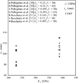
Effect of Modulus of Elasticity of FRP
While some guidelines ([1], [11], and [13]) assume that as the modulus of elasticity of FRP increases, the effective bond
Fig. 2. Effect of Modulus of Elasticity of FRP on Effective Length
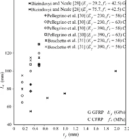
Effect of Thickness of FRP Laminates
The effective bond length depends on the FRP laminates stiffness, which, in turn, is a function of the FRP modulus of elasticity and thickness. However, there is an inconsistency in the different guidelines equations regarding the relationship between the thickness of the FRP laminates and the effective
Fig. 3. Effect of FRP Thickness on Effective Length
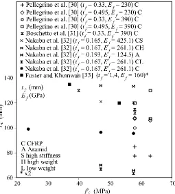
Effect of Concrete Compressive Strength
The effective bond length between FRP laminates and concrete is affected by the physical and mechanical properties of concrete. In particular, the effective bond length and the concrete tensile strength vary in inverse proportion to one another. However, since the concrete tensile strength is a function of the concrete compressive strength, the effective bond length is also a function of the concrete compressive
Fig. 4. Effect of Concrete Compressive Strength on Effective Length
Proposed Formula
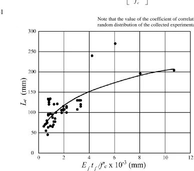
Based on the above investigation of 37 different beam specimens, it was concluded that the effective bond length increases with the increase the stiffness (i.e. modulus of elasticity and thickness) of the FRP laminates, and decreases with the increase of the concrete compressive strength. The effective bond lengths of the available experimental data (51 different specimens) were plotted against the product of Ef ·tf /fc'
in order to derive the most accurate empirical formula that represents this wide range of experimental data performed by 9 different researchers [26], [27], [28], [29], [30], [31], [32], [33], and [34]. It is important to mention that the author has performed a preliminary parametric study to investigate different plots and equation types in order to obtain the equation that yields the most accurate results when compared to the available experimental data. However, after calculating the correlation coefficient for different assumed best-fit curve, it was observed that the most accurate curve is the power curve with the following equation (Fig. 5):
1
0
e
L
(1)
where β0 and β1 are constants to be assigned based on the boundary conditions.
'
c f f
f
t
E
(2)
In order to perform a regression analysis, Eq. 1 is linearized by applying a logarithm function to both sides of the equation as follows:
)
ln(
)
ln(
)
ln(
L
e
0
1
(3)
The linear regression analysis is applied to Eq. 3 where y = ln([Le]), x = ln([α]), m = β1, and b = ln(β0). The slope m, intercept b, and the coefficient of correlation R are calculated as follows:
2 2)
(
)
(
)
)(
(
x
x
n
y
x
xy
n
m
(4)
n
x
m
y
b
(
)
(5)
2 2
2 2
)
(
)
(
)
(
)
(
)
)(
(
y
y
n
x
x
n
y
x
xy
n
R
(6)where:
∑xy = sum of products x1y1 + x2y2 + x3y3 + …. + xnyn ∑x = sum of values of x1 + x2 + x3 + …. + xn
∑y = sum of values of y1 + y2 + y3 + …. + yn ∑x2 = sum of products x
N = number of test samples
Solving Eqs. 4, 5, and 6 yields the following values:
361
.
0
m
8681
.
0
b
555
.
0
2
R
Thus:361
.
0
1
m
371
.
7
0
b
e
And the proposed equation is:
361 . 0
'
371
.
7
c f f ef
t
E
L
(7)Note that the value of the coefficient of correlation reflects the random distribution of the collected experimental data.
Fig. 5. Le vs. Ef tf /fc' (different experimental data)
Comparison with Different Guidelines
The proposed equation is compared to the existing design
equations presented by different codes and researchers by
means of Le(ana.)/Le(exp.). The mean and standard deviation are
calculated for each of the presented equations as shown in table.
Table III
Mean and Standard Deviation of Le(ana.)/Le(exp.) of Different Equations Ref . Propose d Equation [7][10] [14][17 ] [10] [2][11] [12][13 ]
[14] [15] [16] [18]
[19] [1] [20] [21] [22] [23] [24] [25]
µ 1.024 0.971 1.05
2 0.457 0.96 1 0.68 6 0.80 9 1.02 6 0.41 9 1.01 8 1.66 4 2.55 6 0.92 9 1.41 5 1.18 8
σ 0.224 0.229 0.24
5 0.314 0.22 8 0.16 3 0.19 2 0.24 4 0.28 8 0.36 1 0.41 3 0.67 4 0.22 8 0.70 5 0.31 3
Table III are calculated as follows:
n
L
L
n
i e exp.i i ana e
1 ( ).) (
(8)
n
L
L
n
i e exp i i ana e
12
.) (
.)
(
(9)where µ = mean value, σ = standard deviation, Le(ana.) = analytical value of the effective bond length, and Le(exp.) = experimental
value of the effective bond length.
By inspecting the mean and standard deviation values of
Table , it can be observed that the proposed equation gives the most accurate results among the compared equations. This is because it has been derived based on the largest set of data.
Summary and Conclusions
One of the major failure mechanisms in concrete structures strengthened with external FRP laminates is the debond between concrete and FRP. Various researchers and guidelines proposed different equations to predict the effective bond
length. This is because these equations are derived based on a limited number of experimental data and test specimens. This research provides a wide range of experimental data (51 test specimens) collected from 9 different researchers. This paper compares the equations of 14 different guidelines and researchers to the available experimental data. In addition, a new equation is proposed to calculate the effective bond length based on 51 test samples. It has been concluded that the effective bond length increases with the increase of the stiffness of FRP laminates and decreases with the increase in concrete compressive strength. These conclusions contradict with the equations proposed by some of the researchers and guidelines ([1], [2], [11], [12], and [13]). This is because the proposed equation in based upon a wide set of date performed by various researchers.
NOTATION
b = intercept of the linearizedpower equation
β0 = power equation constant assigned based on the boundary conditions
β1 = power equation constant assigned based on the boundary conditions
CFRP = carbon fiber reinforced polymer
Ef = modulus of elasticity of FRP laminates
fco = characteristic value of the concrete compressive strength
fck = cylinder axial compressive strength of concrete
fctH = tensile strength of surface concrete
fctm = mean tensile strength of concrete
f’c = specified compressive strength of concrete
ft = ultimate tensile strength of FRP laminates
GFRP = glass fiber reinforced polymer
H-CFRP = High stiffness carbon fiber reinforced polymer
Le = effective bond length
Le(ana.) = analytical value of the effective bond length
Le(exp.) = experimental value of the effective bond length
m = slope of thelinearizedpower equation
n = number of test samples
PBO = Poly-para-phenylene-Benzo-bis-Oxazole. R = coefficient of correlation
tf = thickness FRP laminate
fad = design value of FRP tensile stress at the end anchorage fad,max = design value of maximum anchorable FRP tensile stress
= Standard deviation
∑xy = sum of products x1y1 + x2y2 + x3y3 + …. + xnyn ∑x = sum of values of x1 + x2 + x3 + …. + xn ∑y = sum of values of y1 + y2 + y3 + …. + yn ∑x2 = sum of products x
12 + x22+ x32+ …. + xn2
µ = Mean value
Compliance with Ethical Standards: The author declare that they have no conflict of interest.
REFERENCES
[1] ACI Committee 440, "Guide for the Design and Construction of Externally Bonded FRP Systems for Strengthening Concrete Structures," American Concrete Institute, ACI 440.2R-08, Farmington Hills, MI, USA, 2008.
[2] Maeda, T., Asano, Y., Sato, Y., Ueda, T., and Kakuta, Y., "A Study on Bond Mechanism of Carbon Fiber Sheet," Proceedings of the Third International Symposium (FRPRCS-3), Non-metallic (FRP) Reinforcement for Concrete Structures, Sapporo, Japan, V. 1, 1997, pp. 279~286.
[3] Chajes, M. J., Finch, W. W. Jr., Januszka, T. F., and Thonson, T. A. Jr., "Bond and Force Transfer of Composite Material Plates Bonded to Concrete," ACI Structural Journal, V. 93, No. 2, 1996, pp. 295~303.
[4] Täljsten, B., "Defining Anchor Lengths of Steel and CFRP Plates Bonded to Concrete," International Journal of Adhesion and Adhesives, V. 17, No. 4, 1997, pp. 319~327.
[5] Holzenkämpfer, O., "Ingenieurmodelle des Verbundes Geklebter Bewehrung für Betonbauteile," Dissertation, TU Braunschweig, 1994 (in German).
[6] Niedermeier, R., "Zugkraftdeckung bei klebearmierten bauteilen (Envelope line of tensile forces while using externally bonded reinforcement)," Doctoral Dissertation, TU München, 2000. (In German).
[7] Neubauer, U. and Rostásy, F. S., "Design aspects of concrete structures strengthened with externally bonded CFRP-plates,", Proceedings of the 7th International Conference on Structural Faults and Repair, Concrete and Composites, V. 2, 1997, pp. 109~118.
[8] Yuan, H., and Wu, Z., "Interfacial Fracture Theory in Structures Strengthened with Composite of Continuous Fiber," Proceeding Symposium of China and Japan: Science and Technology of 21st Century, Tokyo, Sept., pp. 142~155.
[9] Yuan H., Wu., Z., and Yoshizawa, H., "Theoretical Solutions on Interfacial Stress Transfer of Externally Bonded Steel/Composite Plates," Structural Engineering/Earthquake Engineering of JSCE, Japan, V. 18, No. 1, 2001, 12 pp.
[10] FIB Task Group 9.3, "Externally Bonded FRP Reinforcement for RC Structures," Technical Report, Fib Bulletin 14, CEB-FIP, Lausanne, Switzerland, 2001, 130 pp.
[11] ISIS Canada, "Strengthening Reinforced Concrete Structures with Externally-Bonded Fibre Reinforced Polymers (FRPs)," ISIS Design Manual No. 4, Canadian Network of Centers of Excellence on Intelligent Sensing for Innovative Structures, Winnipeg, Canada, 2001.
[12] Khalifa, A., Gold, W., Nanni, A., and M.I., "Contribution of Externally Bonded FRP to Shear Capacity of RC Flexural Members," Journal of Composites and Construction, Vol. 2, No. 4, 1998, pp. 195–202.
[13] Canadian Standards Association, "Design and Construction of Building Components with Fiber-Reinforced Polymers," CSA S806-02, Rexdale, Ontario, Canada, 2002.
[14] The Concrete Society, "Design Guidance for Strengthening Concrete Structures Using Fibre Composites Materials," Concrete Society, CS-TR-55-UK, Technical Report No. 55, 2nd ed., Report of a Concrete Society Committee, Berkshire, UK, 2004.
[15] Eurocode 8-3, "Design of Structures for Earthquake Resistance; Part 3: Assessment and Retrofitting of Buildings, " European Standard, EN 1998-3, Brussels, Belgium, 2004, 133pp.
[16] SIA166, Klebebewehrungen, "Externally bonded reinforcement,"
Schweizerischer Ingenieur- und Architektenverein-SIA, Zurich, Switzerlans, 2004, 44pp.
[17] National Research Council, "Guidlines for the Design, Execution and Control of Strengthening Measures through Fibre-reinforced Composites," CNR-DT 200/04, Rome, Italy, 2004, 53pp. [18] CIDAR, "Design Guideline for RC Structures Retrofitted with FRP
and Metal Plates: Beams and Slabs," Draft 3, Submitted to Standards Australia, CIDAR/CBIR, Australia, 2006.
[19] Chen J., F., and Teng, J., G., "Anchorage Strength Models for FRP and Steel Plates Bonded to Concrete," Journal of Structural Engineering-ASCE, V. 127, No. 7, 2001, pp. 784~91.
[20] Yang, Y., X., Yue, Q., R., and Hu, Y., C., "Experimental study on bond performance between carbon fiber sheets and concrete,"
Journal of Building Structures, Vol. 22, No., 2001, pp. 36~42 (in Chinese).
[21] Sato, Y., Asano, Y., and Ueda, T., "Fundamental Study on Bond Mechanism of Carbon Fiber Sheet," Concrete Library International, Vol. 37. 2001, pp. 97~115.
[22] Niu, H., Wu, Z., "Prediction of Debonding Failure Load due to Flexural Cracks of Concrete for FRP-Strengthened Structures,"
Proceedings of the 5th International Conference on Fiber-Reinforced Plastics for Fiber-Reinforced Concrete Structures, FRPRCS-5, Vol. 1, 2001, pp. 361~70.
[23] Lu, X., Z., "Study on FRP-concrete interface," PhD thesis, PRC: Tsinghua University, 2004 (in Chinese).
[24] Ouezdou, M. B., Belarbi, A, and Bae, S., W., "Effective Bond Length of FRP Sheets Externally Bonded to Concrete,"
International Journal of Concrete Structures and Materials, Vol. 3, No. 2, 2009, pp. 127~131.
[25] Wu, Z., Islam, S., M., and Said, H., "A Three-Parameter Bond Strength Model for FRP-Concrete Interface," Journal of Reinforced Plastics and Composites, Vol. 28, No. 19, 2009, pp. 2309~2323. [26] Eurocode 2, "Design of concrete structures - Part 1-1: General rules
and rules for buildings," European Standard, EN 1992-1-1, Brussels, Belgium, 2004, 225pp.
[27] Sato, Y., Kimura, K., and Kobatake, Y., "Bond Behavior between CFRP Sheet and Concrete (Part 1), " Journal of Structure and Construction Engineering of AIJ, Japan; Vol. 500, 1997, pp. 75~82. (in Japanese).
[28] Bizindavyi, L, and Neale, K, W, "Transfer lengths and bond strengths for composites bonded to concrete," Journal of Composites for Construction, Vol. 3, No. 4. 1999, pp. 153~60. [29] De Lorenzis, L., Miller, B., and Nanni, A., "Bond of
Fiber-reinforced Polymer Laminates to Concrete," ACI Material Journal, Vol. 98, No. 3, 2001, pp. 256~264.
[31] Boschetto, G, Pellegrino, C, Tinazzi, D, and Modena, C, "Bond Behaviour between FRP Sheets and Concrete: an Experimental Study," Proceedings of the 2nd International Congress, FIB, Naples, Italy, June 2006 CD-Rom, paper ID: 10-12.
[32] Nakaba, L., Kanakubo, T., Furuta, T., and Yoshizawa, H., "Bond Behavior between Fiber-Reinforced Polymer Laminates and Concrete," ACI Structural Journal, Vol. 98, No. 3, 2001, pp. 359~367.
[33] Foster, S. J. and Khomwan, N., "Determination of Bond Stress Versus Slip for Externally Bonded FRP from Standardized Bond Strength Tests," Proceeding of the International Symposium on Bond behavior of FRP in Structures, Hong Kong, 2005, pp. 85~90. [34] Iwashita, K., Wu, Z., Ishikiwa, T., Hamagushi, Y., and Suzuki, T., "Bonding and Debonding Behavior of FRP Sheets under Fatigue Loading," Advances in Composites Materials, Vol. 16, No. 1, 2007, pp. 31~44.
![Fig. 1. Anchorable tensile stress related to anchoring length (after Niedermeier [6])](https://thumb-us.123doks.com/thumbv2/123dok_us/1354042.1644138/2.612.86.528.297.692/fig-anchorable-tensile-stress-related-anchoring-length-niedermeier.webp)