212
Soft Switched Current Fed Modified Push Pull
Converter For Pv Application
Rameshbabu a, Barnabas paul glady, Sundar rajan G T, Sivachidambaranathan VAbstract: In this paper present a soft-switched current fed modified push–pull converter for PV application. The main objective
of this work is to reduces the switching losses, increase the voltage gain without increasing turns ratio of high frequency transformer and increase the efficiency. The switching losses of proposed converter is reduced high frequency transformer primary-side switches are turned OFF at the zero-current Switching condition through parallel resonance. In addition, the turn ratio of the transformer can be reduced by using a voltage-doubler of secondary side. The performance of the proposed converter is verified by simulation and experimental results.
Keywords: ZCS, push pull converter, Efficiency, Voltage gain, turns ratio, PV.
————————————————————
1.
INTRODUCTION
Due to the thoughtful difficulties of ecological contamination and fossil fuel fatigue, photovoltaic (PV) energy has established excessive care as a source of renewable energy. Over the past few decades, the demand for renewable energy has increased significantly due to the disadvantages of fossil fuels and greenhouse effect. Among various types of renewable energy sources (RES), solar energy and wind energy have become the most promising and attractive because of advancement in power electronic technique. Photovoltaic (PV) sources are used nowadays in many applications as they own the advantage of being maintenance and pollution free. In the past few years, solar energy sources demand has grown consistently due to Increasing efficiency of solar cells, manufacturing technology improvement, economies of scale [1]-[4]. Numerous types of inverter circuits and equivalent control approaches for PV generation have been broadly considered. In the earlier, PV generation schemes are created on centralized inverters were mostly employed, interfacing a huge quantity of PV modules to the grid. The PV modules are separated into cascaded or shunt connections done via string diodes for huge generation. These systems have boundaries, misalliance damage between PV modules, switching and conduction losses in the string diodes. If there are no losses accompanying with string diodes, it will rise the overall efficiency related to the centralized inverter. Though, dc-module-form combined into individually PV module has recognized recently. Each output terminal of an individual dc module is connected to the load. Hence cable wiring is simple, future extension of the system is easy [5]-[8]. To interface the PV module to the load high frequency& efficient DC-DC converters are preferred. This type of converter is mainly used for low to medium power ranges with reduced ripple.
Due to high frequency operation reduction ripple is easy, hence efficiency of the system increased. In this category Fly back, forward, Bridge and push pull topologies are discussed [9]. Out of which push pull converter is selected due to that Isolation between PV module and load, simple in construction, need less components, used increased power level compared to fly back and forward converter [10]. The conventional push–pull converter also has switching losses due to hard switching [11]-[12]. Transformer losses also occur due to high step-up ratio to connect the low voltage of the PV module to the high voltage of the DC line. So due to this problem the output of the conventional system is reduced and also the overall efficiency is less [13]-[14].
The main objective of this Renewable based soft switching current fed push pull converters are used to
To reduce the losses in power circuit like switching loss and iron and copper loss by using soft switching
To get more output voltage by using voltage doubler in the system.
To increase the efficiency of the solar power output.
Use of High frequency transformer reduced turns ratio
The section 2 modes of operation of the soft switching push pull converter is explained in detail in order to analyse performance of the converter. In section 3 describes the simulation results of proposed converter. In section 4 developed prototype model experimental results are shown. Finally conclusion and future scope is discussed in section 5.
2.
OPERATION OF THE MODIFIED PUSH
PULL CONVERTER
_________________________________
Rameshbabu a, Barnabas paul glady, Sundar rajan G T, Sivachidambaranathan V Department of EEE, SIST, Chennai,India-600119
Fig. 1 Modified push pull converter
The interval of operation describes the various stages of operation during one switching period. The converter operation is repetitive in the switching cycle. One complete switching cycle is divided into ten modes. The current flows have five repetitive modes operating in the opposite direction every switching period.
• Current flows through switch S1. The flow of the resonant current at the resonant tank is reversed. The leakage inductor current iLk decreases linearly. • The switch current iS1 increases and iS2 decreases
shaping resonant curves. The current of the resonant tank becomes negative. This mode is finished when iS2 reaches zero.
• The negative current iS2 flows through the antiparallel diode of the switch S2. The current of the resonant tank is decreased to the minimum and increased again. This mode is finished when the magnetic energy in the boost inductor Lbst starts to decreases.
• A switch S2 is turned OFF, magnetic flux in the core is formed. Cr is charged by the current of the transformer. This mode is over when Cr is charged completely. At this time, power is transferred to the output through the diodes of the voltage-doubler
• After Cr is discharged completely, leakage inductor current iLk flows toD2 and transfers power to the voltage-doubler. The boost inductor current iLbst decreases linearly and the induced secondary current of the transformer decreases slowly. This mode is ended when S2 is turned ON.
• In modes 6–10, the converter operates oppositely.
3.
SIMULATION OF MODIFED PUSH PULL
CONVERTER
The validity of the proposed converter can be demonstrated with the help of MATLAB/SIMULINK tool and experimental hardware prototype. The fig.2 shows that the Simulink diagram of the modified push pull converter. The modified push pull converter is constructed using the Simulink blocks such as PV model, MOSFET power switch, High frequency transformer, pulse generator and voltage doubler. The PWM signals of the MOSFET switches are generated using pulse generator with the switching frequency of 50Khz.
Fig.2 Simulation circuit of modified push pull converter
Fig.3 Simulated solar model
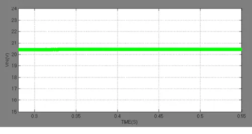
The above fig.3 shows the simulated solar model for the Input voltage of a Proposed Soft Switching push-pull Converter. The equivalent model of PV is represented by current source in parallel with diode and the series and parallel resistance. The output voltage from solar panel is 20VDC i.e. shown in fig.4
Fig.4 solar output
214 Fig.5 Driving pulses of MOSFET
Fig.6 MOSFET current and voltage
Fig.7 ZCS in switch S1
Fig.8 ZCS in switch S2
The fig.7 and fig.8 are indicates ZCS of the switches S1 and S2 in the converter. This ZCS operation of switches reduces the switching losses of the both switches. The above fig shows the simulated waveform ZCS2 of a Proposed Soft Switching push-pull Converter.
Fig.9 Inductor current ILB
Fig.10 Resonance capacitor voltage
The simulated waveform of input inductor current ILB of a Proposed Soft Switching push-pull Converter is shown in fig.9. The input current measured is 18A DC. From this input current waveform, it indicates that the input ripple current measured is very low. The fig.10 shows the simulated waveform of resonant capacitor voltage VCr of a Proposed Converter. The voltage measured in the resonant capacitor is 150VAC. This value of the voltage is very high value compared to the conventional push-pull converter.
The fig.11 indicates the Output voltage of a Proposed Soft Switching push-pull Converter. The measured value of the output voltage is 300VDC. It is output voltage from the voltage doubler circuit. It is nearly 15 times of the solar voltage.
Fig.11 Output current
The output Current of a Proposed Converter is shown in fig.12. The output current is in the range of 0.37ADC with load resistance of 100Ω.
4.
EXPERIMENTAL VERIFICATION
The proposed push pull current fed inverter hardware prototype set up consist of PV module, proposed converter with high frequency and voltage doubler, PIC microcontroller, Driver circuit, Opto-coupler and power supply. A set of solar modules are connected in series and parallel to provide required DC voltage to the input of the proposed converter. The proposed converter is consist of input inductor, high frequency transformer, MOSFET switch, rectifier with voltage doubler. The input DC voltage is converted in to high frequency AC signal with the help of MOSFET switches and high frequency transformer. The high frequency AC signal is converted to Boost DC with help of rectifier with voltage doubler.
Fig.12 Over all Hardware diagram
Fig.12 PV DC output voltage
Fig.14 Driving pulse of the MOSFET switch
Fig.15 Snap shot of the prototype and experimental result
216
and regulator. The hardware result shows that the input DC voltage from PV panel is 20V DC and the output DC voltage from the proposed current fed push-pull inverter is 304V DC. This experimental result is similar to the simulation result.
5.
CONCLUSION AND FUTURE SCOPE
The soft-switched current fed modified push–pull converter for PV application is presented. The voltage gain of the proposed converter is 15 times of the input voltage without increasing the turns ratio of the transformer. The efficiency of the proposed converter is increased by reducing the switching losses of proposed converter is reduced high frequency transformer primary-side switches are turned OFF at the zero-current Switching condition Finally performance of the proposed converter is verified by simulation and experimental results.The proposed work is limited for the use of PV Panel. If the power obtained from PV oscillates steady state value, it can’t able to maintain as the constant voltage at output under rapidly varying irradiance levels. The proposed concept is extended by use of adaptive P&O algorithm and Incremental Conductance algorithm to obtain maximum power point tracking under rapid varying irradiance levels.
REFERENCES
[1]. R. Gonzalez, J. Lopez, P. Sanchis, and L. Marroyo, ―Transformerless inverter for single-phase photovoltaic systems,‖ IEEE. Trans. Power Electron.,vol. 22, no. 2, pp. 693–697, Mar. 2007.
[2]. Babu, A. Ramesh, and T. A. Raghavendiran. "Analysis of non-isolated two phase interleaved high voltage gain boost converter for PV application." In Control, Instrumentation, Communication and Computational Technologies (ICCICCT), 2014 International Conference on, pp. 491-496. IEEE, 2014. [3]. Babu, A. Ramesh, and T. A. Raghavendiran.
"Performance analysis of novel three phase High step-up dc-dc interleaved boost converter using coupled inductor." In Circuit, Power and Computing Technologies (ICCPCT), 2015 International Conference on, pp. 1-8. IEEE, 2015.
[4]. Babu, A. Ramesh, and T. A. Raghavendiran. "High voltage gain multiphase interleaved DC-DC converter for DC-DC micro grid application using ıntelligent control." Computers & Electrical Engineering, ISSN:0045-7906, Vol.74, pp.451-465, March 2019.
[5]. D. Meneses, F. Blaabjerg, O. Garc´ıa, and J. A. Cobos, ―Review and comparison of step-up transformerless topologies for photovoltaicAC-Module application,‖ IEEE Trans. Power Electron., vol. 28, no. 6, pp. 2649–2663, Jun. 2013.
[6]. K. Selvamuthukumar, M. Satheeswaran and A. Ramesh Babu,‖ Single phase thirteen level inverter with reducednumber of switches using different modulation techniques‖ ARPN Journal of Engineering and Applied Sciences, Vol. 10,
No 22, ISSN 1819-6608,pp 10455-10462, Dec. 2015.
[7]. Saravanan, M., and A. Ramesh Babu. "High Power Density Multi-Mosfet-Based Series Resonant Inverter for Induction Heating Applications." International Journal of Power Electronics and Drive Systems (IJPEDS) ISSN: 2088-8694, Vol. 7, No. 1 pp. 107-113, March 2016.
[8]. Lee, H.S., Kang, B., Kim, W.S. and Yoon, S.J., 2019. Reduction of input voltage/current ripples of boost half-bridge DC-DC converter for photovoltaic micro-inverter. Solar Energy, 188, pp.1084-1101.
[9]. Trujillo, C.L., Velasco, D., Figueres, E., Garcerá, G. and Ortega, R.,‖ Modeling and control of a push–pull converter for photovoltaic microinverters operating in island mode‖ Applied energy, Vol.88, No.8, pp.2824-2834, 2011.
[10]. Kim, Y.H., Shin, S.C., Lee, J.H., Jung, Y.C. and Won, C.Y., 2013. Soft-switching current-fed push–pull converter for 250-W AC module applications. IEEE Transactions on Power Electronics, 29(2), pp.863-872.
[11]. Petit, P., Aillerie, M., Sawicki, J.P. and Charles, J.P., ―Push-pull converter for high efficiency photovoltaic conversion‖ Energy Procedia, Vol.18, pp.1583-1592, 2012.
[12]. T. C. Lim, B. W. Williams, S. J. Finney, H. B. Zhang, and C. Croser, ―Energy recovery snubber circuit for a dc-dc push-pull converter,‖ IET Trans. Power Electron., vol. 5, no. 6, pp. 863– 872, Jul. 2012.