Automated Pick and Place Solution Based on
Raspberry Pi
Jorge Costa&, Graça Almeida#&1, Armando Cordeiro#*&§£2
#
ADEEEA, *LCEC, &ISEL, Instituto Politécnico de Lisboa 1959-007 Lisboa, Portugal
§
INESC-ID Lisboa, £Sustain.RD ESTSetúbal
Abstract — This paper presents an automated pick and place solution based on Raspberry Pi module. The proposed solution allows identifying objects in random positions through image processing and performing the pick and place operation using an industrial robotic arm. The solution is composed by a conveyor belt carrying wood blocks of different dimensions, which arise randomly at the beginning of the conveyor and moving to an area where they can be picked up by the robot. Above the conveyor belt there is a video camera connected to a Raspberry Pi that controls simultaneously the robot and the conveyor. The conveyor belt is driven by a three-phase induction motor powered by a Variable Frequency Drive (VFD) which is continuously adjusted by the Raspberry Pi in order to assure the correct operation. During the operation the controller performs the detection of the objects and their dimensions, using image-processing techniques, allowing to follow the wood blocks along the entire motion. An algorithm was developed in order to optimize the processing time of the proposed solution. The solution presented in this article resulted from the work developed in a master’s thesis in Electrical Engineering. Throughout the article are presented some of the technical solutions adopted, as well as some experimental results, which confirm the proper operation and the limitations of the proposed solution.
Keywords — Automation, Robotics, Image Processing, Electrical Drives, Industrial Control
I.INTRODUCTION
In an increasingly industrialized world that moves towards the concepts established by the thematic of Industry 4.0, it makes no sense to have highly dynamic and versatile equipment, such as industrial robots and controllers, performing continuously the same tasks thought lifecycle without receiving new inputs and different configuration from the outside world. Although the concept of industry 4.0 has been announced for industrial environments [1], its application was gradually extended to the rest of the society, which allowed to generate a wave of social creativity around all the existing possibilities of technology appliances inside and outside the industry. The objective of keeping industrial, commercial or housing processes operating interactively according
to human needs represents a radical change in the way that systems were originally designed. These new concepts have led many engineering companies and schools to develop and search for new solutions to overcome some of the challenges ahead. Some concepts related with the Industry 4.0 are not exactly new, such as the Artificial intelligence (AI), but this new paradigm increased the interest about the development of new solutions of this type. Artificial intelligence is the result of several years of research into technologies and solutions that could make machines work less dependent on human intervention. As an example of its presence is the well-known MIT's Computer Science and Artificial Intelligence Laboratory [2], which dates from the beginning of the 1960's. The evolution of computer systems in recent years has made it possible. The idea of having interconnect equipment which can control themselves, providing information to other devices according to human preferences and can diagnose certain problems with humans or themselves automatically is now a reality.
Robots as flexible and multifunctional equipment in the industry have a very important role in this new paradigm. They are certainly one of the key elements in achieving the intended objectives proposed by the fourth industrial revolution. Nevertheless, to achieve such objectives the robots must integrate several other solutions such as different kind of sensors, controllers and actuators. Additionally, artificial vision also becoming natural partner of the robots extending their capabilities. All these elements together provide to industrial robotics new tools to perform tasks with or without human intervention and making the collaboration between both reliable and safe.
automation, robotics, artificial vision, image processing algorithms, analogue and digital electronics, digital communication and advanced informatics, giving to students the necessary background [3],[4]. The proposed solution is based on Raspberry Pi module which is not an equipment with characteristics to use within industrial environments but it is a good tool for use in the laboratory, allowing to extend student’s knowledge about several issues and is very valuable to develop several works at very low cost.
II.INDUSTRIALROBOTICS
Since the first industrial robot was created (the Unimate in 1961 [5]), the industry has been making a massive use of this equipment. When General Motors applied it for the first time, quickly they realized the potential in their assembly lines, due to the safety they could provide to operators, allowing the transportation of cast metal parts and the execution of welds automatically, both functions considered hazardous. Over the years this equipment has become increasingly compact, fast and precise, until the present day where they are applied in the majority of the manufacturing processes. Organizations, such as ISO (International Organization for Standardization) or RIA (Robotic Industries Association) [6] classify the robots according to the type of joints they have, namely: Linear, SCARA, Articulated, Parallel and Cylindrical. The fact that they behave as flexible mechanical assemblies requires that their study is also carried out with tools of classical mechanics, such as forward and inverse kinematics, allowing, from the point of view of the movements control, that these are carried out according to their position or relative position of each of its joints respectively. The use of these techniques presents great advantages during the commissioning, whether using point-to-point (PTP) or continuous and controlled (CP) programming methods. For example, in the automotive body painting, speed variations during the application of paint may result in unacceptable results from the point of view of quality. In this situation the CP method is more favourable because it produces a smooth curve for the trajectory [7]. During movements in open spaces where is necessary to navigate from point A to point B without obstacles that could create a dangerous situation, the PTP method is the most indicated since the robot makes the movements of joints as short as possible to reach the destination point.
Safety of humans has always been one of the main concerns about industrial robotics. Most robots must operate in a safety cell since they perform operations very quickly and without appropriate barriers accidents are almost unavoidable. Usually such robots have a wide working area and apply considerable forces in the manufacturing processes. Over the last years, a new generation of robots emerged with capabilities to operate side by side with
humans sharing the same workspace, the Collaborative Robots. Such robots operate usually at moderate speeds and with reduced forces.
Although the equipment falling within this category work with in permanent power and torque limiting control, and has some special mechanical characteristics in order to reduce the damage caused in case of impact, it should be noted that the technical specification ISO / TS 15066 [8] complemented by ISO 10218-1 [9] and ISO 10218-2 [10] refers to "industrial robot systems‖ and it does not apply to non-industrial robots.
III.IMAGEPROCESSING
Image processing has made great advances in the last two decades with new development of new algorithms [11] which permit a robust and widely applicable system across a range of robotic platforms and varying environments. Usually, when talking about ―image processing‖ or ―artificial vision‖, is compared a set of hardware and software with a human characteristic. In fact, video cameras generally use a base structure like the human eye, consisting of the outer lens (cornea), mobile (crystalline) lens, and finally nerve cells (photosensitive sensors). The term ―artificial‖ brings us to the subject of artificial intelligence. While the human being has gradually acquired knowledge along its evolution, creating new associations at the cognitive level as a function of what he visualized in his daily life, in artificial systems these associations also need to be created in order to provide the desired functionalities. This requires the existence of a chain of image processing and extraction of its contents according with the interest to the application (Fig. 1). The first step in this process is the image acquisition with future treatment in order to obtain data. Depending on the application the image can be performed with the information provided by separated images in several layers according with the colour model (RGB (Red, Green, Blue), CMYK (Cyan, Magenta, Yellow and Black), HSV (Hue, Saturation, Value), among others), or converting them to grayscale images [12].
Data acqui sition
Pre-processing
Segmen tation
Feature
detection Tracking
Input video Track video
Fig. 1. Architecture of a typical image processing system [13]
computationally as pixel matrices allow several types of mathematical and sequential approaches to the study of image processing.
When a digital camera captures an image, it is necessary to make the pre-processing that can consist of a variety of transformations such as the grayscale transformation, image smoothing, edge detectors and restored the image through of filters. The segmentation block is used to obtain the edge image thresholding, edge relaxation and the Hough transforms. The last phase is the extraction features that will be used to recognize the objects.
One of the most important operations in image processing is the convolution of matrices, which works with transformation matrices, typically 3x3, consisting of a central pixel and a neighbourhood (remaining points of the matrix). With these matrices is possible to apply a variety of filters.
Some of the most commonly used filters are [11]:
Median: application of the statistical concept in n x n matrices to carry out a neighbourhood approximation in order to restrict Gaussian noise (see fig. 2);
Fig. 2. Image before (left) and after (right) the application of the median filter
Morphological operations: application of algebraic operations between a defined sets of pixels (probes) and the images to be treated;
Thresholding: conversion of pixels above or below a given threshold T to 0 or 1 (black or white).
Fig. 3. Result of thresholding of a section of Fig. 2
Outlines are the most ordinary information used in image processing systems to identify objects and acquire their physical characteristics. To do this it is necessary to identify the boundaries, i.e., the edges of the objects. Within an image this information is
determined from the detection of neighbour points with similar luminous intensity values, close to other points with quite different values, this is done with the computation of a local derivative operator. The derivative is obtained in digital images by convolution sum. A 3x3 mask is often used. By limiting an image only to edge information, data that may not interest is deleted and thus reducing computational effort.
Some of the algorithms most used to determine the edges are [7],[11]:
Sobel: The responses of the Sobel masks, equations (1) and (2), at any point of the image are combined with equation (3) and equation (4) in order to obtain the gradient and orientation of each pixel of the image. The result of the convolution operation is a new image where the horizontality and verticality are highlighted;
(1)
(2)
(3) (4)
LoG (Laplacian of Gaussian): Although quite similar to the previous one, this operator uses the second derivative which gives the gradient magnitude only, see the LoG mask equation (5);
(5)
Canny: This is one of the most used methods, it is used as a simple detector of horizontality and verticality of edges. This method looks for the optimal solution of the edge detection and is mathematically more complex than previous methods and required the creation of an algorithm to reduce computational effort [14]. The Canny edge detector first convolves an image with a Gaussian mask, then it is estimated local edges and then find the local maxima, also known as the non-maximal suppression, after that the magnitude is calculated, and a threshold is applied.
Having the information of the edges, it is necessary to organize the data of the contours to obtain the characteristics of the objects. To organize this information there are several algorithms and the most common are based on [7]:
search is performed around the pixel following a set of specific orders [7];
Image scanning: Quite similar to the previous one, the pixels are analysed in the context of the complete image. This is very useful for sequential image analysis. An example is the algorithm of Suzuki and Abe [15].
To determine the physical characteristics of the objects, such as the centroid, area and slope, it can be used:
Invariable Moments: A method that explores the theory of algebraic invariants, which defines these moments (common to other fields such as statistics and classical mechanics) as invariants - do not change - in translation, rotation and change of body scales. Some of the leading names behind the creation and consequent development of this method are Hu [16], Flusser and Suk [17];
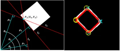
Hough Transform: Created by Paul Hough [18] it’s a tool to determine the inclination angle of objects. It starts by performing a transformation from the Cartesian coordinate plane into the polar coordinate plane (Hough plane), of multiple lines that intersect with each point of the contour to be analysed. This transformation results in an accumulation of points in the new plane. The locations with the highest intensities correspond to the points that define each of the lines that form the contour (see Fig. 4).
Fig. 4. Hough Transform Application
IV.IMPLEMENTATIONAND EXPERIMENTALRESULTS
A. Project description
This didactic project proposes the implementation of an automatic system to detect and capture objects with capability to separate the objects according to their physical characteristics. The objects are randomly placed on a running conveyor belt, a USB camera (with a resolution of 1280x960) installed on the top of the conveyor allows to identify and follow the objects along the conveyor until they reach the point of capture. The conveyor is powered by a Variable Frequency Drive (VFD) and the speed can be adjusted according with the created algorithm. When the objects reach the point of capture, an articulated robot pick up the objects in the current
position and inclination. Multiple objects could be tracked simultaneously, and the speed of the conveyor is automatically adjusted to guarantee that all the objects will be picked up. The control of the entire system (see Fig. 5) was performed by a main controller (Raspberry Pi© 3 Model B) programmed in C ++. The proposed architecture is a low cost and quite flexible solution.
Fig. 5. Diagram block of the proposed solution
According with Fig.5 is possible to see that the proposed solution integrates several subsystems. Each subsystem has different communication interfaces and different I/O characteristics which required the development of specific hardware and software in order to control the system in "real time" (very small latency).
B. Image Processing
The software created was divided into two programs, the first one being the main program responsible for managing the entire process, and the second one being a configuration/calibration tool for the implemented image processing systems.
Due to different cartesian coordinates from the point of view of the robot and camera, it was important to define the spatial relationship between both (see Fig. 6). These two systems can be related by a homogeneous transformation matrix.
Fig. 6. Robot and camera coordinate axis systems
coordinates. Also, the lighting system and the initial position of the robot are parameters that must be introduced or calculated with the calibration tool.
The developed algorithm acquires images that are cyclically analyse according to some of the functions described in section III. The model of the image processing algorithm is presented in Fig. 7.
Fig. 7. Model of the image processing algorithm used
C. Tracking Algorithm
Since this project is an emulation of an industrial application in which the movements of the objects are linear, it made sense that the prediction realized during the movement of the objects was based on the uniformly accelerated rectilinear motion.
It should be noted that the image processing is not performed on the entire image, but only on the intended ROI (region of interest), which allows a significant reduction in processing time. First the inspection is done at the ROI_Initial (Fig. 8) in order to verify if a new object have appeared to carry out the monitoring, the movement is from left to right. Then any objects that are already being tracked, by analysing the areas where ROI_tracking (Object tracking Region of Interest) is predicted to be updated. With this information is possible to command the robot to capture the object when it is in capture position.
Fig. 8. Identification of the critical zones of the tracking algorithm
D. Interfaces
The communication with the robot was done through digital commands sent to the serial interface of this
device (RS232C interface). The low-voltage TTL serial interface of the Raspberry Pi was connected to a signal converter (MAX3232) in order to match the different voltages between these interfaces (see Table I).
Table I – Signal Comparison between Raspberry PI and Robot
Logical Value Raspberry Pi RS232
0 0 V +3 V a +15 V
1 3.3 V -3 V a -15 V
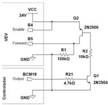
To adjust the I/O interface with the VFD it was necessary to convert the controller signals (3.3V) to the voltages used by the digital inputs of the drive (24V). A circuit based on two NPN and PNP transistors was thus created (Fig.9).
Fig. 9. I/O digital interface circuit between the VFD and the controller (Raspberry Pi)
A digital-to-analog (DAC) converter (MCP4922) controlled by SPI (Serial Peripheral Interface) communication was adopted to send the speed signal (Fig. 10) reference from the Raspberry Pi to the analog input interface of the VFD.
Fig. 10. SPI communication structure of the DAC MCP4922
E. Experimental Results
Fig. 11. Object being transported from the beginning of the conveyor (left picture) and the anthropomorphic robot executing the movement to pick the object (right picture)
V.CONCLUSIONS
An automated didactic low-cost solution developed for pick and place objects using an anthropomorphic robot and an image processing system was presented in this paper. It was used a camera with a resolution of 1280x960.
The software created was divided into two main programs: one for the calibration tool and another for the tracking system. The calibration tool is responsible to corelate space coordinates into image coordinates. Also, the lighting system and the initial position of the robot are parameters that must be introduced at this initial phase. The tracking system is the main program for the image processing analyses and mainly consists consist the grayscale transformation, edge detectors, the Hough transforms and some calculus of the centroid and orientation of the object. Regarding the operation of the tracking system, the pick and place solution was successfully developed.
In order to conclude about the performance of the proposed solution a brief evaluation was made to the processing times. Considering that the camera was running at a speed of 30 fps (frames per second), or approximately 0.033s per frame. The average image processing time was about 0.21s, the same is to say that it was performed 4.76 cycles/s. Considering that the maximum speed of the conveyor belt was 2.8cm/s, it is possible to conclude that the position of the object was updated at every 0.59cm. The results are within an acceptable value for the initial purpose for this work.
REFERENCES
[1] Sabine Pfeiffer, ―The Vision of ―Industrie 4.0‖ in the Making—a Case of Future Told, Nanoethics‖ (2017) 11: 107. [Online]. Available: https://doi.org/10.1007/s11569-016-0280-3
[2] MIT’s Computer Science and Artificial Intelligence Laboratory. [Online]. Available: https://www.csail.mit.edu [3] Rupa Gurram, Sweatha Suresh. B, Sneha. B. R, Sushmitha.
R. "Object Tracking Robot on Raspberry PI using OpenCV", International Journal of Engineering Trends and Technology (IJETT), V35(4),160-163 May 2016. ISSN:2231-5381.
www.ijettjournal.org. published by seventh sense research group
[4] Abyash Gautam, Deepak Rasaily, Sejal Dahal. "Microcontroller Controlled Automated College Bell", International Journal of Engineering Trends and Technology (IJETT), V32(4),184-187 February 2016. ISSN:2231-5381. www.ijettjournal.org. published by seventh sense research group
[5] J. Wallén, ―The history of the industrial robot,‖ Linköpings Universitet, 2008
[6] ANSI/RIA, ―ANSI/RIA R15.06-2012 - Industrial Robots and Robot Systems —Safety Requirements,‖ 2012 [7] Mikell P. Groover, M. Weiss, R. N. Nagel, Nicholas. G.
Odrey, Industrial Robotics: Technology, Programming, and Applications, McGraw-Hill, 1986
[8] ISO, ―ISO/TS 15066:2016 - Robots and robotic devices -- Collaborative robots‖
[9] ISO, ―ISO 10218-1:2011 - Robots and robotic devices -- Safety requirements for industrial robots -- Part 1: Robots‖ [10] ISO, ―ISO 10218-1:2011 - Robots and robotic devices --
Safety requirements for industrial robots -- Part 2: Robot systems and integration‖
[11] Rafael C. Gonzalez, Richard E. Woods, Digital image processing, 3rd Edition, Prentice Hall, 2007
[12] M. Sonka, V. Hlavac, R. Boyle, Image Processing and Machine Vision, 2nd Edition, ISBN 0-534-95393-X, 1998 [13] V. Sundari, S. Rani e S. Prabhu, Tracking of Moving
Objects in Video Sequences. [Online]. Available: https://www.educreation.in/store/sample/book1715E.pdf, 2018
[14] J. Canny, ―A Computational Approach to Edge Detection‖, IEEE Transactions on Pattern Analysis and Machine Intelligence (Volume: PAMI-8, Issue: 6, Nov. 1986),1986 [15] S. Suzuki e K. Abe, ―Topological Structural Analysis of
Digitized Binary Images by Border Following‖. [Online]. Available: https://doi.org/10.1016/0734-189X(85)90016-7, 1985
[16] M.-K. Hu, ―Visual Pattern Recognition by Moment Invariants‖. [Online]. Available:
http://www.sci.utah.edu/~gerig/CS7960-S2010/handouts/Hu.pdf, 1962
[17] J. Flusser e T. Suk, ―Pattern recognition by affine moment invariants,‖ 1993
![Fig. 1. Architecture of a typical image processing system [13]](https://thumb-us.123doks.com/thumbv2/123dok_us/8581844.1719084/2.595.311.522.593.657/fig-architecture-typical-image-processing.webp)