http://www.sciencepublishinggroup.com/j/ijics doi: 10.11648/j.ijics.20180302.14
ISSN: 2575-1700 (Print); ISSN: 2575-1719 (Online)
Example Based Light Sources Generation Method for 3D
Scenes
Linyi Hu, Zhihong Wang
State Key Labortory of Virtual Reality Technology and Systems, Beihang University, Beijing, China
Email address:
To cite this article:
Linyi Hu, Zhihong Wang. Example Based Light Sources Generation Method for 3D Scenes. International Journal of Information and Communication Sciences. Vol. 3, No. 2, 2018, pp. 42-49. doi: 10.11648/j.ijics.20180302.14
Received: August 14, 2018; Accepted: September 13, 2018; Published: September 18, 2018
Abstract:
Lighting design is very important to improve rendering quality for some 3D scenes that are used in the VR applications with night simulation. Determining the properties of the light sources requires a large amount of artwork, especially when the number of lights is large. Most virtual scenes always have some geometric objects with similar structures and shapes. Based on this observation, this paper proposes an example based light source generation method by using local geometric similarity. An example model decorated with light source and a target model are input to this method. First this paper segments both model into parts with SDF segmentation algorithm, and find matched parts between the example model to the target. Then two methods are applied to transfer the light sources decorated on the parts of the example model to the corresponding parts of the target model. Minimum spanning tree based light transfer method is used to generated light sources for target parts with the same pattern as lights layout on its corresponding parts from the example model. While texture synthesis based method tiles the light texture generated from the example parts on the surface of the target parts. At last, the position and colors of the light sources are refined. The results demonstrated that this method can quickly and effectively edit light sources for large-scale scenes, reduce the amount of art work and achieve good visual effects.Keywords:
Light Sources Generation, Texture Synthesis, Minimum Spanning Tree, Voxelization1. Introduction
With the continuous development of virtual reality technology, the models in the virtual scene become more and more complex, and the requirements of the scale and accuracy of the environment modeling are getting higher and higher. Virtual reality applications need high quality models and 3d scenes, also in different conditions, day and night. Light source design in 3d scene needs experts to design and spend a lot of time. Some models and scenes have thousands of light sources. It is too tedious to put them by hand with the editing software. Some smart modeling techniques provide a way to model the virtual scenes more efficient, while there still remains a challenge to modeling light sources with those smart methods.
However, in a large-scale scenes, there are many models that are similar, and the light source layout is also a similar pattern. This paper proceed from known examples and design
light sources for large-scale scenes based on the similarity of shapes. This method can proceed from the predefined model that has been edited by the light source and perform light source transmission on the target model according to the local geometric similarity. And this method can quickly obtain better results and greatly reduce the work time.
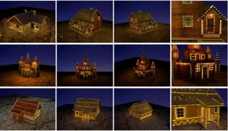
Figure 1. Result of light generation. The first column is source model. The next three is generation result.
The contribution of this method are summarized as following:
1) This paper provided a pipeline to transfer light sources from the example model with existing light sources to the model with similar local geometry details.
2) With minimum spanning tree based light transfer method proposed in this paper, the light sources with the same pattern can be generated on the parts of target even if the size of target part is total different from the example one.
3) A texture synthesis based light transfer method is introduce to generate the repeated pattern of light layout of example model on the surface of the target parts.
2. Related Work
Virtual scene modeling is one of the most important research directions of virtual reality. In the area of geometric modeling of three-dimensional scenes, many domestic and foreign research institutions and researchers have made important contributions to the geometric modeling of three-dimensional scenes. For example, Professor Paul Debevec's research team at the University of Southern California, Hong Kong University of Science and Technology Professor team, Professor Chen Baoquan of Shandong University, Professor Huang Hui of Shenzhen University, and Professor Wang Guoping of Peking University all have accumulated in this area. At the same time, with the improvement of the requirements for the scene rendering effect, highlighting the subtlety of the scene model and the immersion of the scene, the design and editing of light sources for large-scale scenes has become one of the most popular research directions. The current light source
generation methods are mainly divided into light source design based on sketch and light source design based on advanced description.
2.1. Sketch Based Light Source Design
In 2007, Okabe [1] proposed an intelligent interactive lighting brush system, they provide a user interface, artists can effectively design custom image-based ambient lighting, can handle ambient light. Marks [2] introduced a design gallery system that uses a user interface to help designers explore the parameter space and achieve ideal lighting effects. But their system uses computers to evaluate lighting configurations rather than solutions. Their system provides several interfaces, light source placement and light source selection for picture rendering, including standard light sources and image-based. Opacity and color transmission, and function control in particle systems. Fabio Pellacini [3] applied the reverse lighting method to the theater stage lighting design.
2.2. Advanced Description Based Light Source Design
algorithm consists of two major steps. The first step estimates an initial lighting configuration by light sampling and clustering. The second step optimizes the lighting configuration by alternatively selecting a light cut on the light hierarchy to determine the number of representative lights and optimizing the lighting parameters using the simplex method.
The current light source modeling method has a big problem. First of all, the geometric scenes that can be handled by the existing methods have a simple structure and a small number of light sources. Existing methods are usually proposed for three-dimensional scenes that contain only a single geometric object or several objects, and the number of light sources ranges from a few to several tens. With the advancement of acquisition equipment and geometric modeling techniques, the scale of three-dimensional scenes that need to be processed becomes larger and larger, the structure becomes more and more complex, and the range that can be processed becomes more and more limited. Second, the user interaction operation adopted by the existing methods is relatively simple and can only express relatively rough lighting effects. The existing method usually uses the interactive interface to allow the user to draw and mark the effect of lighting. Then the algorithm uses an optimization algorithm to optimize the position. The user enters the details through multiple interactions and iteratively generates the final effect, but the final effect may not be achieved.
In addition, the existing method has a single input information, and most of the methods are based on the user's input of an image indicating lighting or shadow information that is input interactively. Therefore, this work proposed a large-scale scene-based intelligent editing method based on local geometric similarity, which can be input by pre-defining the models that have already arranged the light sources. According to the local geometric similarities, the light source positions and parameters are transmitted, and the effects similar to the predefined light sources are achieved. It can quickly deal with large-scale scenarios, get better results.
3. Details
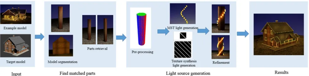
The light source generation based on the sample model consists of three steps. First, the model is processed, the light source of the sample is arranged, the model is segmented and the corresponding sample is retrieved according to the shape. After the split part model and the corresponding sample are obtained, this work uses two methods, starting from the sample, to generate the light source on the part model. These two methods are based on the method of minimum spanning tree and based on texture synthesis. Finally, refining the generated light source is done, including the color and position, and then render it in 3dmax to get better results. The pipline show in Figure 2.
Figure 1. Pipline.
3.1. Find Matched Parts
In this process, there are several steps. First of all, this paper selected the sample case model, arranged the light source for the pre-defined model, and manually split the model according to the shape to obtain each sample model with specific significance. Combine each sample model with its corresponding light source to obtain a source sample.
After getting the sample model and light source, it is time to starte processing the input model. For each input model, The process of model segmentation is needed. Model segmentation is the process of decomposing a model into smaller and meaningful part models. There are many mature model segmentation algorithms. Yu-Kun Lai [6] proposed fast segmentation using random walk. Kalogerakis [7] proposed a method for marking a segmented model. In this section, this segment process is relying on the Shape Diameter Function(SDF) [8]. Given a input surface mesh, the
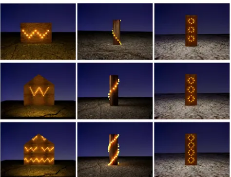
Figure 3. Difference between two methods. Light source generation through different method. The first row is examples and the second row is light source generation based on MST, and the third row is based on texture synthesis.
So far this work have got sample models and light sources. And the input model is segmented. At the same time, this work get the matching relationship between the segmented part and the sample model.
3.2. Light Source Generation
According to the arrangement of light sources, this paper have divided two different ways to generate light sources. One is based on a minimum spanning tree and the other is based on texture synthesis. Figure 3 shows the differen results of generation.
3.2.1. Pre-processing
Before the generation of the light source, some pre-processing work needs to be performed on the part models, including voxelization of the model, direction correction, and geodesic calculation.
Model voxelization is the first step. There are many voxelization ways. One way to achieve real-time voxelization by rendering scene geometry on a virtual frame buffer connected to a 3D voxelized 2D tablet. Another method uses deep pixels, which correspond to voxelized whole lines, one for each voxel. And several fast voxelization techniques deviate from the traditional graphics pipeline and use a common GPU programming API such as CUDA to define novel voxelization pipelines. VoxelPipe computes [10] the 3D voxelization directly with a fast, sort-middle, approach, or a conservative, sort-last approach. This work calcates the bounding box of the part model and select a voxel resolution. Then determining the size of the required voxelization block and dividing the bounding box space. For each voxel, iterate through each triangle to determine if there is a triangle overlap with the voxel block. If there is an overlap, this work consider that the voxel block is occupied. After traversing all the voxels, the model voxelization process is completed. Since it takes a long time to traverse the triangles in the CPU,
this paper use the automatic interpolation of triangle rasterization in the OpenGL rendering pipeline. When running the shader, this work calculated the three-dimensional space position of each fragment and determined the fragment occupie voxel blocks and completed the voxelization of the model automatically. For each light source, this paper find the nearest voxel, use this voxel as the attachment location of the light source. In the next calculation, replace the light source position with the position of this voxel.
For the paired models may have different directions, we should calibrate the direction. Prior to this, this work voxelized the models. This paper use Principal Component Analysis (PCA) to find the three directions with the largest variance of all voxels. The first step is to calculate the covariance matrix for all voxels in Equation 1. Then find the eigenvalues of the covariance matrix and sort the eigenvectors according to eigenvalues. Finally, the original voxels are transformed using a matrix of sorted eigenvectors so that the pairing models have the same direction.
cov X, Y ∑ (1)
The geodesic distance is the shortest distance to find two points on the surface of a three-dimensional object. In riemannian geometry [11], the curve on the surface is a geodesic, if and only if it is a straight line, or its main normal vector is a normal vector. In 2013, Crane [12] proposed a new approach to computing distance based on heat flow. In this section, this paper use a method similar to the single-source shortest path to get any two points' geodesic distance on the surface. For a pair of points, breadth-first search through voxels is used. In each iteration, the 26 neighborhood voxel of each voxel are searched. This step stops the search until the search for the specified location. This step will get the geodesic distance between any two points on the model.
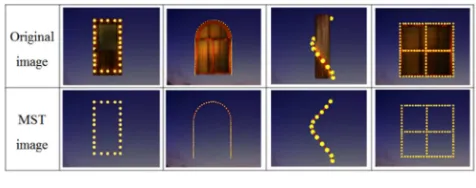
3.2.2. Minimum Spanning Tree Based Light Sources Generation
Figure 4. MST based generation.
This method relies on the voxel correspondence between part model and sample model. After previous model voxelization and direction correct process, this work can calculate the corresponding voxel mapping relationship. First of all, normalizing the model is needed. This step calculates the center point of the model, and translates the model to the origin. Then this step calculates the bounding box of the model, and scales the model into the unit cube. After this process, for each voxel of the sample model, this work finds the nearest voxel in corresponding part model. The mapping relationship Map , is obtained which is a voxel of sample model and is a voxel of corresponding part model.
Algorithm 1 MST based light source generation
Input: source light lights, source and target voxel voxels, voxelt
Output: target light light 1: for each lights do
2: attachVoxel = findAttachVoxel(lights, voxels) 3: end for
4: MST(attachVoxel) 5: modelNormalize()
6: Map(pi -> qi) = calcateVoxelMap(voxels, voxelt) 7: lightt = NULL
8: for each attachVoxel do
9: lightt+ = Map(attachVoxel -> voxelt) 10: end for
11: updateMSTEdgeDistance(light) 12: lightCountAd justByDistance(light) 13: return lightt
Then this paper use the mapping Map , generated in the front section. For each light source voxel, finding the matched voxel in part models by the mapping Map , . This process have get the initial light source position in part model. Then it is time to get the corresponding minimum spanning tree in the part model based on the minimum spanning tree established in its corresponding sample model. And then this work recalculates the geodesic distance of each corresponding edge. This step compares current geodesic distance with original geodesic distance. According to the length of the corresponding spanning tree and insertion factor
, the light source is proportionally generated on the path of the geodesic. After this process, the light source count and position will adaptive automatic. Of course, the points on the spanning tree will be merged if corresponding side length is smaller. Insertion process is introduce in Equation 2, and the is length ratio and ! from 1 to " # 1. The detail is show in Algorithm 1.
%& ' ()"*
+,-." / 0 # %& ' (2)
3.2.3. Texture Synthesis Based Light Source Generation
Algorithm 2 Texture Synthesis based light source generation
Input: source light lights, source and target voxel voxels, voxeld
Output: target light light
1: textures = findTextureOfSurface(voxels) 2: textured = findTextureOfSurface(voxeld) 3: for each lights do
4: attachVoxel = findAttachVoxel(lights, voxels) 5: setTexture(attachVoxel, textures)
6: end for
7: textureSynthesis(textures, textured) 8: lightt = textureMapping(textured, voxeld) 9: return lightt
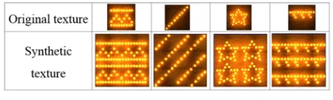
Texture synthesis [13] is a process that synthesizes a texture of any size through a limited texture. Charles Han [14] develop a multiscale texture synthesis algorithm. In texture synthesis, it is needed to determine the size of each extended block and the size of the overlap area. First select the initial block to be the starting point of the destination texture based on the initial block size. And then this work expands on this basis. There are three conditions to expand a new area from an expanded area. The only difference is that the area to be expanded overlaps with the expanded area. They may be only in the vertical direction, only overlaps in the horizontal direction and overlaps in both directions. During each expansion, this paper obtain the pixels in the overlapping area and then traverse the original texture to find the closest overlapping area. This paper use Sum of Squared Distance (SSD) to computer the distance between two textures. The SSD is generated in Equation 3 and 1, 2 is each pixel of the texture and ! is each channel.
3345 / ' ∑ 1, 2 6!7 # 8 1, 2 6!7 8
9,:
(3)
pixels on one side of the split path will be expanded. This gives a mask to determine which area should be replace with the original pixel. The detail is in Algorithm 2.
Now this paper uses texture synthesis and texture transfor for light generation. Although, there are many texture transfor method. HQ Dinh make texture transfor during shape transform. Xiaobai [15] Chen offers benefits of both parameterization and texture synthesis approaches, preserving both large and fine-scale patterns of the source properties. In this method, the light source is seen as texture and expand the surface of the model into a texture. Now using texture synthesis to solve the problem that the size difference between the two models. Then the synthesized texture is attached to the model to complete the light source generation.
This method is mainly divided into three steps. The first step is to calculate the texture coordinates of the model surface. This paper assume that the surface of the model where the light source needs to be arranged has been adjusted to the vertical direction by direction adjustment. This work started from the point where the coordinates are the smallest. Divide the search direction into horizontal and vertical directions. In the vertical direction, searching voxel in both up and down. In the horizontal direction, calculating the center of each layer of voxels, and procssing from the direction of the connection between the center and the current voxel are done. This step traverse the voxels in the 8th neighborhood clockwise, and traversed first voxels are used as the direction of expansion. After the expansion, the uv coordinates corresponding to each voxel is obtained and this paper see it as texture. This step see the uv coordinates texture of the part model and corresponding sample model as
;< %& ' and ;< 5 .
Figure 5. Texture Synthesis based generation.
The second step is to generate a texture pixel ;< 5
from ;< %& ' . For each light source voxel, it should get texture coordinates of the voxel. This step set the grayscale of the corresponding pixel in ;< %& ' when there exist a
light source. Through this process, a raw texture is synthesized.
The third step is synthesizing ;< 5 based on
Algorithm 2. Then this work attaches the texture to the model and convert it to a light source. Determines whether each voxel has a light based on the gray level of the synthesis texture. This step will place a light source in the voxel which the grayscale of the pixel in ;< 5 is larger than a
threshold. After this process, the corresponding light source have be generated on the target model. The light source texture synthesis results shows in Figure 5.
3.3. Refinement
The color and position of the light source generated by the above two methods have a certain deviation and need further correction. The refine result shows in Figure 6.
Figure 6. Refine result. The left col is the example model, and the right col is the generation result.
3.3.1. Position Refinement
This paper replace the light source position with the nearest voxel and pass the light source position through the voxel. In this way, the light source may be trapped inside the model during rendering. Therefore it is needed to make further correction to the position of the light source. This work calculates the center of each layer of voxels, links the center of gravity with the voxels that contain the light source, and shifts the light source locations outwardly along the lines. Traversing the mesh to make sure the position of the light source is on the surface of the model. In addition, For some complex forms of light sources, the resulting minimum spanning tree may not be unique. In this case, the light source form may have a variety of conditions. Properly group the light sources according to ensure the stability of the light source is needed.
3.3.2. Color Refinement
4. Conclusion
4.1. Quality
After a sample based light source generation method, a large scale scene with the light source can be quickly generated to obtain a better viewing effect. This paper selects 9 models with light source and invites 20 volunteers for assessment. The result is showed in Table 1. The results show that in most cases, this light source generation can reach the same effect as the sample light source.
Table 1. Evaluation.
Model index Good Fair Medium Bad
Model 1 4 8 6 2
Model 2 8 6 5 1
Model 3 5 7 4 4
Model 4 9 8 2 1
Model 5 3 5 8 4
Model 6 6 8 5 1
Model 7 8 7 3 2
Model 8 4 6 7 3
Model 9 5 6 5 4
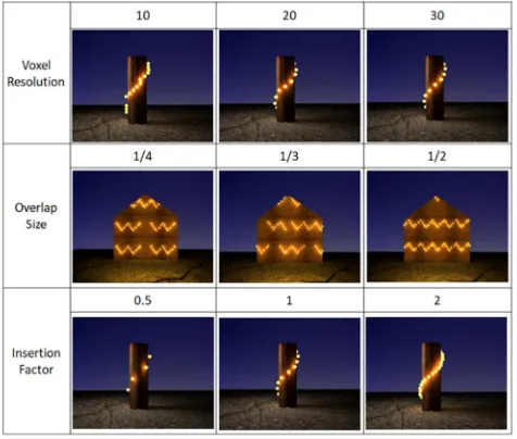
There are many parameters in light source generation. For example, the voxel denisty when making model voxelization, the insert factor when inserting light source in MST edges, and the overlap size when doing texture synthesis process. These parameters are vary important for light source generation results. Parameter control is showing in Figure 7. The higher voxelization resolution will get more precise delivery results, but this will increase the overhead. At the same time, it is necessary to adjust the overlap size appropriately to obtain a better texture synthesis effect. And it can set different insertion factors according to their needs to obtain the light source density.
Figure 7. Parameters control.
Figure 8. Result of MST.
The goal is to be able to generate new light sources starting from the sample model. It need to make the newly generated light source consistent with the light source of the sample model as much as possible. In addition to the visual comparison of the model after rendering, this work also provide a parameterized measurement method. For two different generation methods, this paper set up different comparison methods to measure the generated light effects. For the use of the MST-based generation method, this work calculates the minimum spanning tree edges' length and the number of light sources. This result is show in Figure 8. This parameter maintains a good invariance and ensure sthe consistency of the light source in this process.
For the use of texture synthesis based generation, this work counts surface area of the model and the number of light sources. This result is show in Figure 9 and it shows this method ensures consistent light source density. From the results, the generation method preserves the light source form and features well.
Figure 9. Result of Texture Synthesis.
4.2. Speed
sources, this speed has greatly improved.
Table 2. Time.
Process Information Time
Voxelization 216 triangles, 32768 voxels 1.121s
MST based 91 lights, 216 triangles 1.306s
Texture synthesis based 248 lights, 216 triangles 3.752s
4.3. Conclusions and Future Work
This paper proposes a method for generating large-scale scene light sources based on local geometric similarity according to the requirements of large-scale scene light sources editing. In large scenes, there are usually many geometric models with similar shapes and structures. Through the light source generation method provided in this paper, model segmentation of a large-scale scene can be performed on the segmented model according to an exemplary model containing a light source. The artist only needs to arrange the light source on the representative model, and the light source of the large-scale scene can be completed. This greatly reduces the workload, and can quickly generate a large number of excellent results. According to the limitations of this article, this work will further discuss the light source transmission when the model components are not similar, and seek to be able to intelligently group light sources for better results.
References
[1] Okabe M, Matsushita Y, Shen L, et al. Illumination Brush: Interactive Design of All-Frequency Lighting[C]// Computer Graphics and Applications, 2007. PG '07. Pacific Conference on. IEEE, 2007:171-180.
[2] Marks J. Design galleries: a general approach to setting parameters for computer graphics and animation[C]// ACM SIGGRAPH, 1997:389-400.
[3] Pellacini F, Battaglia F, Morley R K, et al. Lighting with paint [J]. Acm Transactions on Graphics, 2007, 26(2):9.
[4] Schwarz M, Wonka P. Procedural Design of Exterior Lighting for Buildings with Complex Constraints [M]. ACM, 2014. [5] Lin W C, Huang T S, Ho T C, et al. Interactive lighting design
with hierarchical light representation [J]. Computer Graphics Forum, 2013, 32(4):133-142.
[6] Lai Y K, Hu S M, Martin R R, et al. Fast mesh segmentation using random walks[C]// ACM Symposium on Solid and Physical Modeling. ACM, 2008:183-191.
[7] Kalogerakis E, Hertzmann A, Singh K. Learning 3D mesh segmentation and labeling[C]// ACM SIGGRAPH. ACM, 2010:102.
[8] Shapira L, Shamir A, Cohen-Or D. Consistent mesh partitioning and skeletonisation using the shape diameter function [J]. Visual Computer, 2008, 24(4):249.
[9] Chen D, Tian X, Shen Y, et al. On Visual Similarity Based 3D Model Retrieval [J]. Computer Graphics Forum, 2010, 22(3):223-232.
[10] Pantaleoni J. VoxelPipe:a programmable pipeline for 3D voxelization [C]// ACM Siggraph/eurographics Conference on High PERFORMANCE Graphics 2011, Vancouver, Canada, August. DBLP, 2011:99-106.
[11] Petersen P. Riemannian Geometry [M]. Science Press, 2007. [12] Crane K, Weischedel C, Wardetzky M. Geodesics in heat: A
new approach to computing distance based on heat flow [J]. Acm Transactions on Graphics, 2013, 32(5):13-15.
[13] Hoppe H. Appearance-space texture synthesis [J]. Acm Transactions on Graphics, 2016, 25(3):541-548.
[14] Han C, Risser E, Ramamoorthi R, et al. Multiscale texture synthesis [J]. Acm Transactions on Graphics, 2008, 27(3):1-8. [15] Chen X, Funkhouser T, Goldman D B, et al. Non-parametric