Using Lightweight Formal Methods to Model Class
and Object Diagrams
Fernando Valles-Barajas
Department of Information Technology, Faculty of Engineering, Universidad Regiomontana
15 de Mayo 567 Pte., C.P. 64000 Colonia Centro, Monterrey, Nuevo Le ´on, M ´exico phone: +52 81 8220-4733
[email protected], [email protected]
Abstract. In this paper a formal model for class and object diagrams is presented. To make the model the author used Alloy, which is a three-in-one package: a modeling language that constructs software models, a formal method that guides the construction of software models and an an-alyzer that helps find inconsistencies in software models. In the proposed model the entities that form class and object diagrams, as well as the rules that govern how these elements can be connected, are specified. Keywords:Alloy, Formal Methods, UML.
1.
Introduction
A model is a simplified representation of a system; it is useful for document-ing, modeldocument-ing, communicating and analyzing software systems [31]. One of the mechanisms available for making a software model is Unified Modeling Lan-guage (UML), which uses a graphical notation [30]. There are several diagrams in UML, each of these have a specific purpose; for example a class diagram represents the entities of a system as well as the relations between them. A class diagram also represents the attributes of system entities, operations car-ried out by these entities and the responsibilities assigned to them. There are several integrated development environments (IDEs) that facilitate the process of making UML diagrams; for instance ArgoUML, Borland Together and IBM Rational Rose.
Motivation of the paper: In some of the IDEs mentioned above, a novice
[17]. The formal method used in this paper is Alloy; which was developed by the Massachusetts Institute of Technology (MIT) software design group. As will be seen, this formal method is also a modeling language that creates software models in a step-by-step style as well as an analyzer that helps to find incon-sistencies in software models.
Related works: UML is a modeling language used in software processes
(e.g. Rational Unified Process (RUP)) to generate software models. Because of its simplicity, this language has been widely applied in the software industry. One of the disadvantages of UML models is that these artifacts can be inter-preted differently by two members of a software team.
Formal methods are useful techniques to formally specify the syntax of UML diagrams. Models obtained using these techniques are unambiguous. For ex-ample, in [14] Z language is used to specify the syntax of class diagrams. The author remarks that Z is especially useful to formally specify class diagrams involving recursive structures.
Object-Z is an extension of Z language that includes object-oriented con-cepts (inheritance, polymorphism and encapsulation among others). This lan-guage is used in [20] to specify the syntax of class diagrams. Because UML and Object-Z are based both on object-oriented concepts, the mapping be-tween these two languages is more natural than the mapping bebe-tween UML and Z. The definition of UML classes in Z and Object-Z language supports this idea. UML classes specify the structure, behavior and associations shared by a set of objects. While in [14], UML classes were modeled using two Z schemes; one for defining class structures and other for defining behavior, in [20] using Object-Z only one container was necessary to define UML classes. Besides of this, an Object-Z element defining classes can inherit variables and operations from one element that has already been defined. Another paper that formalizes UML class diagrams using Object-Z is [21].
In [2] the authors compare several approaches based on Z and Object-Z to model class diagrams and one of the conclusions made is that thanks to the object-oriented concepts of Object-Z, this modeling language produces more concise models than Z language.
Another modeling language that has been used to specify the syntax of UML class diagrams is the Prototype Verification System Specification Language (PVS-SL), see [4]. In [24] the authors present a tool that analyzes the syn-tax and semantics of Object Constraint Language (OCL) constraints together with UML models and translates them into PVS-SL. The authors tested the proposed tool representing the Sieve of Eratosthenes algorithm, which is an al-gorithm that finds prime numbers, in a UML class diagram and OCL constraints and then this model was converted to a PVS-SL model.
and reasoning based on these models is difficult. To overcome these problems the authors of [15] propose a tool that receives Extensible Markup Language (XML) class diagram specifications as input and generates RAISE Specification Language (RLS) class diagram specification as output. The tool is able to an-alyze and reason of the original class diagrams. It is important to mention that modeling tools (e.g. ArgoUML) can store class diagrams in an XML format; so the input for the proposed tools is easy to obtain.
OCL is the de facto modeling language for adding constraints to UML dia-grams (see [1]). This language was developed because UML constructs alone cannot precisely model situations occurring in real world problems [37]. USE is a UML-based Specification Environment that allows software develop-ers to model UML class diagrams along with OCL constraints ([16]). USE makes it possible to check the consistency of UML models by generating instances of class diagrams.
The authors in [8] argue that OCL has weak semantics and that reasoning from UML diagrams along with OCL constraints is difficult. These authors state that by transforming from OCL to the Isabelle/HOL theorem prover, property analysis of UML diagrams is possible.
Models consist of a dynamic and a static part. UML has a variety of dia-grams covering these two parts. For example the dynamic part may be modeled by state machine diagrams and the static part by class diagrams. In [26] the au-thors present a technique to transform class and state machine diagrams into B modeling language. Models represented in the B notation can be analyzed.
Papers [32], [33], [35], [34], [36] demonstrate that Alloy, which is the model-ing language used in this paper, has been successfully used to formally specify UML diagrams. In [32] the author uses Alloy to model use case diagrams. In [33] state machine diagrams are formalized and an extended version of this pa-per was later presented in [35]. In [34] a model of System Modeling Language (SysML) requirements diagrams using Alloy is included. It is important to men-tion that SysML is a UML profile.
UML collaborations model interactions between entities working together to ac-complish a specific task. In [36], the author formally specify Collaborations.
Other techniques that do not apply formal methods have been used to ver-ify the correctness of UML diagrams. In [19] the authors use constraint pro-gramming for this purpose. UML diagrams along with OCL constraints are first specified as a constraint satisfaction problem and then properties of UML class diagrams are verified with the UMLtoCSP tool.
Methods having roots in artificial intelligence have also been used to specify UML diagrams and to later reason from these models. For example description logic, which is used in artificial intelligence to represent knowledge, is used in [6] and [10] with this objective.
ob-servers. The generalization hierarchy of classes is specified by the inheritance morphism among them.
Graph theory is applied in [22] to model class diagrams as graphs. Class diagrams are mapped as nodes with connecting edges.
Formal methods are based on mathematical logic; for example, Alloy is a modeling language based on set theory, first order logic and relational logic. Equational logic was developed to help in the formal development of programs. A novel method based on equational logic to model class diagrams is presented in [11].
Paper [9] does not apply formal methods to UML class diagrams but it for-malizes aggregation and composition relationships. As the authors mention, there are some UML concepts that are not well specified in the Object Man-agement Group (OMG) documentation of UML. Two examples of these poorly specified concepts are the aggregation and composition relationships. The pa-per models these two relationships as subclasses of a more generic class called the whole-part relationship. In UML 1.x these relationships were modeled as meta-attributes. With the addition in the UML meta-model of one class for each relationship, related characteristics of the aggregation and composition relation-ships can be attached to theses classes. The following characteristics of these two new classes are considered in the author’s proposal: shareability, separa-bility, mutasepara-bility, configurationality, lifetime dependency and existential depen-dency.
As the reader may notice, the papers reported so far are based on the trans-formation of UML class diagrams to a more formal notation to get analyzable and precise models. According with [12], the disadvantage of this approach is that this transformation requires a strong background in mathematics and, un-fortunately, most practitioners do not fulfill this requirement. In [12], the author proposes a technique based on the manipulation of UML class diagrams by us-ing some transformation rules. These rules allow to know if one class diagram is a conjecture of another class diagram. The method presented by the author does not require a strong knowledge of mathematics.
In [23] the authors study the application of graph transformation, which a mature field, to describe the semantics of class, object and state diagrams. The state of a system is represented by object diagrams and these are in turn represented by graphs. A change in the system state is described by using two graphs (representing previous and later states) and by transformation rules. The paper does not present analysis or reasoning of class diagrams based on graph transformation.
Structure of the paper:In this section the motivation of the paper has been
2.
A brief introduction to Alloy
Alloy is a modeling language that has three mathematical tools for making soft-ware models: first order logic, relational calculus and set theory [18]. A system is modeled by representing each system entity and the relations between them. The entities are represented as signatures, which are similar to classes, and the relations as fields of the signatures. Constraints between entities can be speci-fied near signatures as signature facts or outside signatures as facts. Functions are used to specify reusing expressions. Basic constraints can be specified in the relations between signatures by using multiplicity keywords. Alloy has the following multiplicity keywords: one (exactly one), lone (zero or one), some
(one or more) and set (any number). Properties of the model elements can be expressed by using predicates. Alloy has several relational calculus oper-ators that allow to construct complex expressions; for instance the ∧ and ∗ respectively denote the transitive closure and the reflexive-transitive closure of a relation and they are useful for constructing expressions in a relational calcu-lus style. This modeling language also has operators to represent expressions using first order logic; e.g. implication (⇒), not (!), and (&&), or (||) and the bi-implication (⇔). The operators for manipulating sets are: in, union (+), in-tersection (&), difference (−) and equality (=). By using all these operators a modeler can specify software models without ambiguity.
A model in Alloy captures not only the static view of the system but also its dynamic view. It is possible to specify operations that affect the state of the system by using predicates. When a predicate is used to model an operation, the pre-conditions and the post-conditions must be specified.
An attractive characteristic of Alloy is that it does not need a tool to type the formal specification; as will be seen this is written using American Standard Code for Information Interchange (ASCII) characters.
3.
Class diagrams
A class diagram is one of the static diagrams of UML [5]. It is used to represent the entities of a system and the relations between them. A more detailed class diagram can include the features of the entities as well as their responsibilities. There are two types of features: structural and dynamic [13]. Structural features can be subdivided in attributes and associations. Attributes correspond to vari-ables in programming languages. Due to the fact that the associations between classes are represented as variables in programming languages, these are also considered to be structural features. The dynamic part of the classes are the operations, which are implemented by methods in a programming language. There are five types of relations between classes: association, aggregation, composition, generalization and dependency.
An association represents a relation between objects of the same level [29]; this is represented using a solid line connecting two related classes.
can be logical or physical. The classes that participate in these kinds of associ-ations belong to different abstraction levels; one is thewhole-part and the other is thepart-of. Instead of using an association labeled withwhole-part and part-of strings, the solid line that joins two related classes is adorned with a diamond near thewhole-part. Three important characteristics of the composition relation are:
– if thewhole-part is destroyed the smaller parts are also destroyed.
– apart-of may be a part of only one composite at any time [7].
– the diamond near the whole-part is filled (in an aggregation relation this diamond is empty).
Generalization is the process of finding the common features of some classes and then putting these common features into a class. This process is useful to inherit common features from one class to others. The class that passes fea-tures is called superclass and the classes that receive the feafea-tures are called subclasses.
Generalization is also a binary relation between a superclass and a sub-class. The generalization relationship is represented as a solid line with a hol-low arrowhead at the superclass end. In a class diagram several generalizations are usually arranged forming an inheritance hierarchy; this should not be either too deep or too wide [7]. The set of classes above a classc in the inheritance hierarchy are ancestors of this class and they are obtained by using the tran-sitive closure operator. The set of classes below a class c in the inheritance hierarchy are descendants of this class and they also are obtained by using the transitive closure operator [31]. When an instance is generated from a classc, no matter how many ancestors are in this class, only one object is generated with the features of classc and the ancestors of this class [3]. A class inherits the features of its ancestors as well as their relations [25]. Classes in an inher-itance hierarchy can be divided into two types: abstract and concrete. It is not possible to generate an instance from an abstract class. Because of this when a superclass is abstract then the subclasses of this class form a partition [25].
The dependency relation represents the situation in which a change in one element affects other elements. An example of the dependency relation is when a class sends a message to other class; if the receiver of the message changes its interface, then the sender must be changed so that the two classes are still able to communicate. Other examples of dependencies are when a class c1
has a class c2 as a parameter or as a local variable for one of its operations
or when a classc2is in the global scope of a classc1. According with [13] the
dependency relation is anti-transitive. This is formally defined as: ∀c1, c2, c3 :
C(c1Rc2&c2Rc3)⇒not(c1Rc3).
4.
A formal model for object and class diagrams
part specifies the association and dependency relations, the third part presents the generalization relation. The four part specifies the aggregation and compo-sition relation. The last part formalizes the operation definition.
Convention used in this paper:In the models presented in this section, for
the purpose of clarity, the keywords of the modeling language are printed in
bold font.
4.1. The initial model
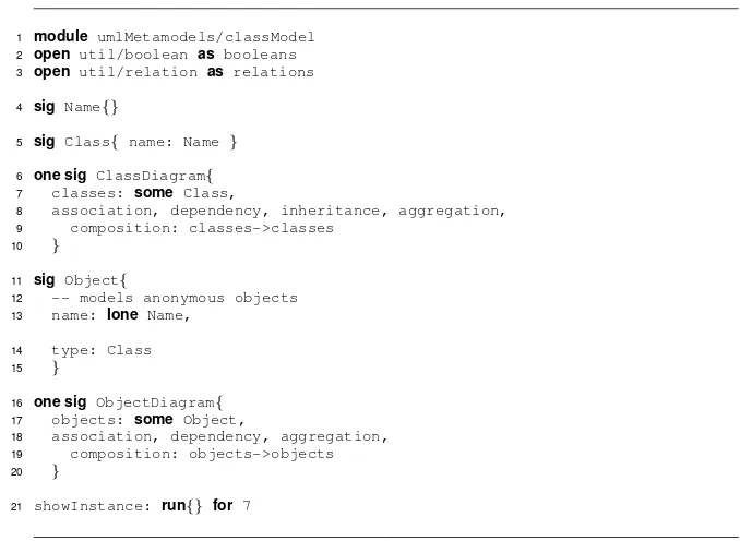
Fig. 1 presents an initial model for class and object diagrams. Line 1 specifies the name of the model (classModel) and the directory for this model (umlMeta-models). Next, in lines 2 and 3, some Alloy libraries are included in the model. Alloy has some built-in libraries that can be used to save time; in this case the model is using two libraries; one to manipulate booleans and another to manip-ulate relations. Line 6 defines a signature for class diagrams. As was mentioned in section 2 the relations between entities (represented in the model as signa-tures) are specified using fields of signatures; for instance, theclassesfield of the signatureClassDiagram denotes a binary relation between the ClassDia-gramsignature and the Class signature. Multiplicity keywords can be used in a relation to constrain the number of participants; for example, the multiplicity keywordsomein theclassesfield means that a class diagram has one or more classes. Multiplicity keywords can be used also to constraint the instances that can be generated from one signature; the keywordone in theClassDiagram
signature indicates that only one instance from this signature can be gener-ated.
Some ternary relations are defined in theClassDiagramsignature; for ex-ample theassociationfield is a ternary relation of the form:
association: ClassDiagram→classes→classes. With the definition of this tion, a class diagram knows all classes that are related by the association rela-tion. A model can be documented in Alloy using comments; for example in line 12 a comment was defined (a comment in Alloy begins with a double-dash). The last line of fig. 1 is theruncommand; by using this command the modeler can generate instances of the model to see if there are inconsistencies.
It is important to mention that in the initial model, the inheritance relation was not defined inside the object diagram signature; the reason for this is to remark the idea that the inheritance relation is really a relation between classes (see section 3).
4.2. Association and dependency relations
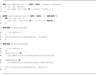
Fig. 2 contains the part of the model where association and dependency rela-tions are specified. In line 1 one function, which is a reusing expression, is de-fined. The functionvalidRelationchecks if two objectso1ando2can be related
1 module umlMetamodels/classModel
2 open util/boolean as booleans
3 open util/relation as relations
4 sig Name{}
5 sig Class{ name: Name }
6 one sig ClassDiagram{
7 classes: some Class,
8 association, dependency, inheritance, aggregation,
9 composition: classes->classes
10 }
11 sig Object{
12 -- models anonymous objects
13 name: lone Name,
14 type: Class
15 }
16 one sig ObjectDiagram{
17 objects: some Object,
18 association, dependency, aggregation,
19 composition: objects->objects
20 }
21 showInstance: run{} for 7
Fig. 1.Initial model
not defined in that module. In signaturesClassDiagramandObjectDiagramthe dependency relation was constrained to be anti-transitive.
4.3. Generalization relation
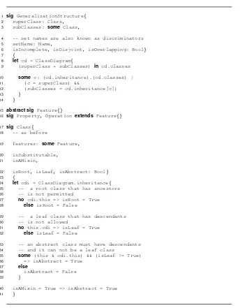
Figs. 3, 4 and 5 present the part of the model where the generalization rela-tion is specified. In line 1 of fig. 3 the signature GeneralizationStructure was defined; this signature represents an inheritance hierarchy. The fieldsetName
is used to document the criterion that was used to form a classification; in early versions of UML this concept was called discriminator. Some constraints over the generalization structure were defined in line 6. TheisCompletefield is used to indicate that all subclasses of classchave been defined. TheisDisjointfield implies that inheritance of a classc from two subclasses of a disjoint general-ization structure is not allowed. The isOverlapping field is the opposite of the
isDisjoint field. Two signature facts were defined in the signature
Generaliza-tionStructure. Line 9 specifies that superclasses and subclasses defined in the
GeneralizationStructuresignature must belong to theClassDiagramsignature.
Line 10 declares that there must be a mapping, in theClassDiagramsignature, between the superclasses and the subclasses defined in the
1 fun validRelation[ r: univ->univ ]:Object->Object{
2 { o1, o2: Object |
3 o1.type->o2.type in r.Class->Class.r }
4 }
5 pred antiTransitive[r: univ->univ, S: set univ]{
6 all s1, s2, s3: S |
7 (s1->s2 + s2->s3) in r => s1->s3 not in r
8 }
9 one sig ClassDiagram{
10 -- as before }
11 {
12 antiTransitive[dependency, classes]
13 }
14 one sig ObjectDiagram{
15 -- as before }
16 {
17 association in
18 validRelation[ClassDiagram.association]
19 dependency in
20 validRelation[ClassDiagram.dependency]
21 antiTransitive[dependency, objects]
22 }
Fig. 2.The association and dependency relations
As can be seen in fig. 3, a class is composed by structural and dynamic features. The static features defined in Class signatures were properties; as-sociations were defined in theClassDiagramsignature as relations (see fig. 1).
TheisSubstitutableboolean field is used to indicate if a subclass is used to
sub-stitute one of its superclasses. A class that does not stand alone and is used to add behavior and structure to other classes is called a mixin class; it is used in multiple inheritance relationship [31].
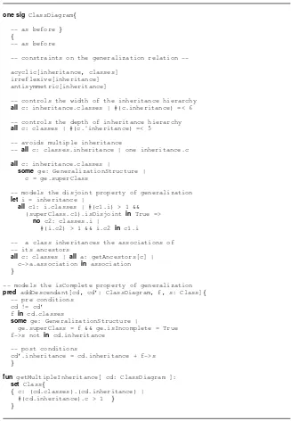
Fig. 4 presents part II of the generalization relation. The properties for the generalization relation are defined in the ClassDiagram signature: acyclic, ir-reflexive and antisymmetric. Two constraints about the form of the inheritance hierarchy were defined: an inheritance hierarchy should not be too deep or too wide. Line 14 constrains the model to only single inheritance. This line was written as a comment because most programming languages do accept multi-ple inheritance. Line 19 of fig. 4 defines theisDisjointproperty defined in fig. 3. In line 26 a signature fact was defined to specify that a class not only inherits the features of its ancestors but also their associations. In fig. 4 a predicate was defined to model theisCompleteproperty of the generalization relation; in this predicate the precondition and post condition were defined.
1 sig GeneralizationStructure{
2 superClass: Class,
3 subClasses: some Class,
4 -- set names are also known as discriminators
5 setName: Name,
6 isIncomplete, isDisjoint, isOverlapping: Bool}
7 {
8 let cd = ClassDiagram{
9 (superClass + subClasses) in cd.classes
10 some c: (cd.inheritance).(cd.classes) |
11 (c = superClass) &&
12 (subClasses = cd.inheritance[c])
13 } 14 }
15 abstract sig Feature{}
16 sig Property, Operation extends Feature{}
17 sig Class{
18 -- as before
19 features: some Feature,
20 isSubstitutable,
21 isAMixin,
22 isRoot, isLeaf, isAbstract: Bool}
23 {
24 let cdi = ClassDiagram.inheritance{
25 -- a root class that has ancestors
26 -- is not permitted
27 no cdi.this => isRoot = True
28 else isRoot = False
29 -- a leaf class that has descendants
30 -- is not allowed
31 no this.cdi => isLeaf = True
32 else isLeaf = False
33 -- an abstract class must have descendants
34 -- and it can not be a leaf class
35 some (this & cdi.this) && (isLeaf != True)
36 => isAbstract = True
37 else
38 isAbstract = False
39 }
40 isAMixin = True => isAbstract = True
41 }
Fig. 3.The generalization relation; part I
1 one sig ClassDiagram{
2 -- as before }
3 {
4 -- as before
5 constraints on the generalization relation
--6 acyclic[inheritance, classes]
7 irreflexive[inheritance]
8 antisymmetric[inheritance]
9 -- controls the width of the inheritance hierarchy
10 all c: inheritance.classes | #(c.inheritance) =< 6
11 -- controls the depth of inheritance hierarchy
12 all c: classes | #(c.ˆinheritance) =< 5
13 -- avoids multiple inheritance
14 -- allc: classes.inheritance | one inheritance.c
15 all c: inheritance.classes |
16 some ge: GeneralizationStructure |
17 c = ge.superClass
18 -- models the disjoint property of generalization
19 let i = inheritance |
20 all c1: i.classes | #(c1.i) > 1 &&
21 (superClass.c1).isDisjoint in True =>
22 no c2: classes.i |
23 #(i.c2) > 1 && i.c2 in c1.i
24 -- a class inheritances the associations of
25 -- its ancestors
26 all c: classes | all a: getAncestors[c] |
27 c->a.association in association
28 }
29 -- models the isComplete property of generalization
30 pred addDescendant[cd, cd’: ClassDiagram, f, s: Class]{
31 -- pre conditions
32 cd != cd’
33 f in cd.classes
34 some ge: GeneralizationStructure |
35 ge.superClass = f && ge.isIncomplete = True
36 f->s not in cd.inheritance
37 -- post conditions
38 cd’.inheritance = cd.inheritance + f->s
39 }
40 fun getMultipleInheritance[ cd: ClassDiagram ]:
41 set Class{
42 { c: (cd.classes).(cd.inheritance) |
43 #(cd.inheritance).c > 1 }
44 }
Fig. 4.The generalization relation; part II
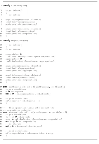
4.4. Aggregation and composition relation
an-1 sig Object{
2 -- as before
3 features: some Feature,
4 classification: set Class,
5 multipleClassification: Bool}
6 {
7 type in ClassDiagram.classes
8 -- models multiple classification
9 classification in
10 getGeneralizationStructure[ type ].subClasses
11 #classification > 1 =>
12 multipleClassification in True
13 -- an object contains the features of
14 -- its type (class) and the ancestors of
15 -- this type
16 let i = ClassDiagram.inheritance |
17 -- * is the reflexive transitive closure operator
18 features =
19 { f: Feature | f in *i.type.features }
20 }
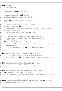
21 fun getAncestors[c: Class]: set Class{
22 -- ˆ is the transitive closure operator
23 { x: Class | x in ˆ(ClassDiagram.inheritance).c }
24 }
25 fun getDescendants[c: Class]: set Class{
26 { x: Class | x in c.ˆ(ClassDiagram.inheritance) }
27 }
28 fun getGeneralizationStructure[ c: Class ]:
29 set GeneralizationStructure{
30 { ge: GeneralizationStructure | ge.superClass = c }
31 }
32 pred mutateClassification[ o: Object, c: set Class ]{
33 o.classification = c
34 }
Fig. 5.The generalization relation; part III
tisymmetric. Two operations were defined related to these relations. The
dele-teObject predicate models the fact that an object that ispart-of another object
in a composition relation cannot exist outside thewhole-part.
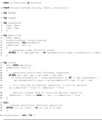
4.5. Operations
1 one sig ClassDiagram{
2 -- as before }
3 {
4 -- as before
5 acyclic[aggregation, classes]
6 irreflexive[aggregation]
7 antisymmetric[aggregation]
8 acyclic[composition, classes]
9 irreflexive[composition]
10 antisymmetric[composition]
11 }
12 one sig ObjectDiagram{
13 -- as before }
14 {
15 -- as before
16 composition in
17 validRelation[ClassDiagram.composition]
18 aggregation in
19 validRelation[ClassDiagram.aggregation]
20 acyclic[aggregation, objects]
21 irreflexive[aggregation]
22 antisymmetric[aggregation]
23 acyclic[composition, objects]
24 irreflexive[composition]
25 antisymmetric[composition]
26 }
27 pred delObject[ od, od’: ObjectDiagram, o: Object]{
28 -- pre conditions
29 o in od.objects
30 not o in (od.aggregation).(od.objects)
31 -- post conditions
32 od’.objects = od.objects - o
33 }
34 -- this operation takes into account the
35 -- composition relation
36 pred addPart[ od, od’: ObjectDiagram, w, p: Object ]{
37 -- pre conditions
38 (w + p) in od.objects
39 w->p in validRelation[ClassDiagram.composition]
40 not w->p in od.composition
41 -- no sharing
42 not p in od.composition[Object]
43 -- post conditions
44 od’.composition = od.composition + w->p
45 }
1 open util/boolean as booleans
2 enum VisibilityKind{ Private, Public, Protected }
3 sig Name{}
4 sig Type{}
5 sig Parameter{
6 name: Name,
7 type: Type
8 }
9 sig Operation{
10 name: Name,
11 visibilityKind: VisibilityKind,
12 parameters: seq Parameter,
13 isAbstract: Bool }
14 {
15 -- parameter names should be unique
16 all disj i, j: #parameters | no (parameters[i].name & parameters[j].name)
17 }
18 sig Class{
19 ops: some Operation,
20 isAbstract: Bool }
21 {
22 -- operations should have different signatures
23 all disj op1, op2: ops | op1.name = op2.name
24 && #(op1.parameters) = #(op2.parameters) => all i: #op1.parameters |
25 op1.parameters[i].type = op2.parameters[i].type => op1 = op2
26 -- if a class has an abstract operation, it must be abstract
27 ops.isAbstract = True => isAbstract = True
28 -- abstract classes have at least one abstract operation
29 isAbstract = True => some o: ops | o.isAbstract = True
30 }
31 fact{
32 -- classes should have different operations
33 all disj c1, c2: Class | no (c1.ops & c2.ops)
34 }
35 showInstance: run{} for 4
Fig. 7.Definition of operations
5.
Comparison of Alloy with other formal methods
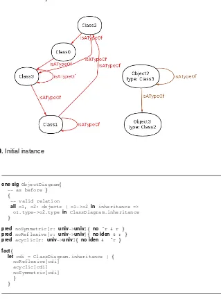
A valid question the reader might have is: what are the advantages of Alloy in comparison to other formal methods? To answer this question let us analyze an excerpt of the meta-model, which is presented in fig. 8. In this fig., the inheri-tance relationship between classes and objects is emphasized.
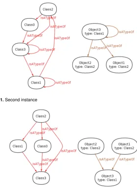
rela-tion was changed toisATypeOf). The reader may notice that this fig. presents some problems, one of these is that the instance of the object diagram does not correspond to the definition of the class diagram instance; the class dia-gram instance states that Class3 is a type of Class1 (Class3 is a subclass of Class1); however in the object diagram instance Object2, which is an instance of Class3, inherits from Object3, which an instance of Class2. In order for the object diagram instance to correspond to the class diagram instance, the type of Object3 should be Class1.
To fix this problem, lines 5 and 6 of fig. 10 were added to the model. Af-ter these lines were added another instance was generated; see fig. 11. The previous problem was solved but the model still has some inconsistencies, e.g. some classes and objects inherit to themselves (Class1, Class3 and Object3). Lines 8 and 15 of fig. 10 solved this problem. After these lines were added to the model, no flaws were found (see fig. 12).
Even thought the last instance does not present the error that classC1
in-herits from class C2 and at the same time class C2 inherits from classC1, it
is possible using the meta-model to generate an instance having this inconsis-tency. Lines 8 and 15 were added to avoid this possible problem.
1 module umlMetamodels/classModel
2 sig Name{}
3 sig Class{ name: Name }
4 one sig ClassDiagram{
5 classes: some Class,
6 inheritance : classes->classes
7 }
8 sig Object{
9 name: lone Name,
10 type: Class
11 }
12 one sig ObjectDiagram{
13 objects: some Object,
14 inheritance: objects->objects
15 }
Fig. 8.An excerpt of the meta-model
6.
Conclusions
Fig. 9.Initial instance
1 one sig ObjectDiagram{
2 -- as before }
3 {
4 -- valid relation
5 all o1, o2: objects | o1->o2 in inheritance =>
6 o1.type->o2.type in ClassDiagram.inheritance
7 }
8 pred noSymmetric[r: univ->univ]{ no ˜r & r}
9 pred noReflexive[r: univ->univ]{ no iden & r }
10 pred acyclic[r: univ->univ]{ no iden & ˜r }
11 fact{
12 let cdi = ClassDiagram.inheritance | {
13 noReflexive[cdi]
14 acyclic[cdi]
15 noSymmetric[cdi]
16 } 17 }
Fig. 10.Corrections for the excerpt of the meta-model
Fig. 11.Second instance
Fig. 12.Third instance
References
1. UML 2.0 superstructure specification. Tech. rep., Object Management Group (OMG) (2005)
2. Amalio, N., Polack, F.: Comparison of formalization approaches of UML class con-structs in Z and Object-Z. In: ZB 2003: Formal Specification and Development in Z and B. Springer-Verlag (2003)
3. Ambler, S.W.: The Elements of UML 2.0 Style. Cambridge University Press (2005) 4. Aredo, D.B.: Formalizing UML class diagrams in PVS. In: Workshop on Rigorous
5. Bennett, S., Skelton, J., Lunn, K.: UML. Schaums outlines, USA (2005)
6. Berardi, D., Calvanese, D., Giacomo, G.D.: Reasoning on UML class diagrams using description logic based systems. In: Proc. of the KI2001 Workshop on Applications of Description Logics. CEUR Electronic Workshop Proceedings (2001)
7. Booch, G., Rumbaugh, J., Jacobson, I.: The Unified Modeling Language User Guide. Addison-Wesley Professional,2ndedn. (2005)
8. Brucker, A.D., Wolff, B.: A proposal for a formal OCL semantics in Isabelle/HOL. Lecture Notes in Computer Science 2410(147-175) (2002)
9. Bruel, J., Henderson-Sellers, B., Barbier, F., Parc, A.L., France, R.: Improving the UML metamodel to rigorously specify aggregation and composition. In:7th Interna-tional Conference on Object-Oriented Information Systems (OOIS ’01) (2001) 10. Cali, A., Calvanese, D., Giacomo, G.D., Lenzerini, M.: A formal framework for
rea-soning on UML class diagrams. In: Proceedings of the13thInternational Sympo-sium on Foundations of Intelligent Systems, LNCS 2366. Springer-Verlag (2002) 11. Clavel, M., Egea, M.: Equational specification of UML+OCL static class diagrams.
Tech. rep. (2006)
12. Evans, A.S.: Reasoning with UML class diagrams. In: Proceedings of the Second IEEE Workshop on Industrial Strength Formal Specification Techniques. IEEE Com-puter Society, Washington, DC, USA (1998)
13. Fowler, M.: UML Distilled: A Brief Guide to the Standard Object Modeling Language. Addison-Wesley,3rdedn. (2003)
14. France, R.B., Bruel, J.M., Larrondo-Petrie, M.M., Shroff, M.: Exploring the seman-tics of UML type structures with Z. In: Proceedings of the Second IFIP Interna-tional Conference on Formal Methods for Open Object-based Distributed Systems (FMOODS’97) (1997)
15. Funes, A., George, C.: Formal fundations in RSL for UML class diagrams. Tech. rep., The United Nations University (2002)
16. Gogolla, M., Bohling, J., Richters, M.: Validating UML and OCL models in USE by automatic snapshot generation. Software and System Modeling 4(4), 386–398 (2005)
17. Hassan, W., Logrippo, L.: Governance Policies for Privacy Access Control and their Interactions. IOS Press, Canada (2005)
18. Jackson, D.: Software Abstractions: Logic, Language and Analysis. MIT Press, Eng-land (2006)
19. Jordi Cabot, R.C., Riera, D.: Verification of UML/OCL class diagrams using con-straint programming. In: ICST Workshop on Model Driven Engineering, Verifica-tion and ValidaVerifica-tion: Integrating VerificaVerifica-tion and ValidaVerifica-tion in MDE (MoDeVVa’2008) (2008)
20. Kim, S.K., Carrington, D.: Formalizing the UML class diagram using Object-Z. In:2nd International Conference on The Unified Modeling Language. Springer, Fort Collins, Colorado (1999)
21. Kim, S.K., Carrington, D.: A formal mapping between UML models and Object-Z specifications. In: ZB 2000, LNCS 1878. Springer-Verlag (2000)
22. Kleppe, A., Rensink, A.: A graph-based semantics for UML class and object dia-grams. Tech. Rep. TR-CTIT-08-06, Enschede (January 2008)
23. Kuske, S., Gogolla, M., Kollmann, R., Kreowski, H.J.: An integrated semantics for UML class, object and state diagrams based on graph transformation. In: Lecture Notes in Computer Science. pp. 11–28. Springer (2002)
25. Larman, C.: Applying UML and Patterns : An Introduction to Object-Oriented Analy-sis and Design and Iterative Development. Prentice Hall, USA,3rdedn. (2004) 26. Ledang, H., Souqui ´eres, J.: Modeling class operations in B: Application to UML
be-havioral diagrams. In:16thAnnual International Conference on Automated Software Engineering, 2001 (ASE 2001) (2001)
27. Meng, S., Aichernig, B.K.: Towards a coalgebraic semantics of UML: Class diagrams and use cases. Tech. rep., The United Nations University (2003)
28. Nolte, T.: Exploring Filesystem Synchronization with Lightweight Modeling and Anal-ysis. Ph.D. thesis, M.I.T., U.S.A. (2002)
29. Pender, T.: UML Bible. John Wiley & Sons (2003)
30. Pilone, B., Pitman, N.: UML 2.0 in a Nutshell. O’Reilly (2005)
31. Rumbaugh, J., Jacobson, I., Booch, G.: The Unified Modeling Language Reference Manual. Addison-Wesley Professional,2ndedn. (2005)
32. Valles-Barajas, F.: A formal model for a requirements engineering tool. In: First Alloy Workshop, co-located with the14thACM/SIGSOFT Symposium on Foundations of Software Engineering (FSE’06). ACM, Portland, Oregon (2006)
33. Valles-Barajas, F.: A formal model for a state machine modeling tool: A lightweight approach. In: 3rd IEEE Systems and Software Week (SASW 2007). IEEE/NASA, Baltimore, Maryland (2007)
34. Valles-Barajas, F.: A metamodel for the requirements diagrams of SysML. IEEE Latin America Transactions 8(3), 259–268 (2009)
35. Valles-Barajas, F.: Use of a lightweight formal method to model the static aspects of state machines. Journal of Innovations in Systems and Software Engineering (ISSE): A NASA Journal 5(4), 255–264 (2009)
36. Valles-Barajas, F.: A precise specification for the modeling of collaboratios. Malaysian Journal of Computer Science 23(1), 18–36 (2010)
37. Warmer, J., Kleppe, A.: The Object Constraint Language: Getting Your Models Ready for MDA. Addison-Wesley Professional,2ndedn. (2003)
Fernando Valles-Barajasobtained a graduate degree in Computer Science at Center for Research and Graduate He received an MS in Control Engineering (1997) and a PhD in Artificial Intelligence (2001) from Monterrey He was a research assistant at Mechatronics department of ITESM campus Monterrey (1997-2001).
He received certification as a PSP Developer from the Software Engineering Institute of Carnegie Mellon
He is member of the IEEE and ACM.
His research interests include topics in Software Engineering and Control Engineering.
Currently he is full-time professor in the Information Technology Depart-ment at Universidad Regiomontana, Monterrey, Nuevo Le ´on, M ´exico. He also teaches modules in Software Engineering.