Using Optical Mouse as a Position Feedback Sensor
for AGV Navigation
Kazi M. Hossain*
and Arif A. Sohel
Abstract-- The control, navigation and interaction with the working environment of Automated Guided Vehicles (AGV) are indispensable processes for material handling in a Flexible Manufacturing S ystem(FMS ) . In this paper, the prospect of using an optical mouse as an economical yet efficient alternative sensor for AGV navigation and control is depi cted. This work emphasizes on the supervision and surveillance over the location, planning and operation of an AGV from a central control panel using a conventional personal computer. An experimental setup is planned and carried out to evaluate the proposed technique for AGV navigation in an indoor environment. The setup included a laboratory-made vehicle, a test bed and an optical mouse as navigation sensor. After the successful accomplishment of the tests, it is concluded that a smart central approach or vehicle approach can be followed for the prediction and avoidance of deadlocking and path planning for the AGV using an optical mouse sensor with a few inexpensive additional developments.
Index Term-- AGV; path planning; optical sensor; indoor environment; robot navigation.
I. INT RODUCT ION
The development of new technologies and specialized processes in the manufacturing p lants introduce large scale production as well as accelerated production process. In order to cope with the production speed and advanced storage management, the idea of using Automated Guided Vehic les (A GV) was developed for the purpose of transportation of semi-finished and finished products to various locations of a plant such as machining units, assembly station, testing and quality control section and packaging stations. Thus, AGV application ensures fle xible and effic ient process flow in an industry. A vital part of an AGV system is the control and navigation of the vehicle. In this paper a different approach for AGV navigation is suggested using optical mouse used with personal computers. An A GV can be described as a mobile robot that follows markers or wires on the floor, or uses vision or laser to navigate on industry floors for mate ria l handling including storage, retrieval and exchange between
Manuscript received March 19, 2013.
Kazi M. Hossain received his B.Sc. in Mechanical Engineering from Bangladesh University of Engineering and Technology, Dhaka, Bangladesh in 2013. e-mail: [email protected]
Arif A. Sohel received his B.Sc. in Mechanical Engineering from Bangladesh University of Engineering and Technology, Dhaka, Bangladesh in 2013 .e-mail: [email protected]
mach ines[1]. Laser ranging technology usually supports a position and orientation computing rate of around 8 Hz [2]. Some formation control la ws are a lso proposed in diffe rent publications as easy alternatives for A GV control and navigation [3]. Over the past several decades AGV systems are widely accepted in manufacturing plants. One of the ma jor causes behind the popularity of such systems is that they require a little construction or floor alternation [4] to support transport carriers. In addit ion, A GV system is equipped with the proven navigation, align ment, safety and control system [5]. The develop ment of A GV control not only speaks about the industrial applicat ions but also shares the area of office and domestic service applications like partially autonomous wheelchair sand indoor and outdoor robot navigation. The key questions for the navigation of an automatic guided vehicle are the acquisition of current position of the vehicle, goal and the Way to accomplish the task [6]. Deadlocking is one of the ma jor challenges in AGV navigation and it can be avoided by using an efficient control and navigation system. Severa l researchers have carried out e xperiments regarding Dead lock-Detecting algorithm during the past several years [7, 8].
Conventional AGV Systems use wired and non-wired navigation and guidance. Wired guidance, stripe guidance, off wire/stripe guidance, light-house navigation are among the common A GV navigation systems [5]. The wire less method of navigation was first introduced in the mid - 1980s and another revolutionary technique known as Inertial or Gyro navigation was brought in during the mid -1990s.
Diffe rent types of optical sensors are used for A GV navigation now-a-days including e xpensive LA DAR (Light Detection and Ranging) to the low -priced photodiodes. Laser navigation supports a speed up to 2 to 3 meters per second using transponders or smart ma rks [ 9]. So me systems use Universal Se ria l Bus (USB) ca mera for a v ision based approach for line detection and recognition as well as obstacle avoidance [10].
In recent years works have been done for finding a new way of a reliable and effic ient navigation system that requires ine xpensive installation and easy control using an optica l mouse [12, 13]. While the prev ious projects focused predominantly on the use of an optical mouse as a positional sensor, in this project the emphasis was given on the central monitoring, control and personnel interface of the system. The proposed AGV system is demonstrated here by build ing a rover and mounting an optical mouse sensor beneath it as a position sensor. The mouse was a wireless device and the communicat ion between the user and AGV was a lso wireless so that it could navigate without restraints within a perimeter of 10 mete rs. The travelled path of the rover could be followed as well as maneuvered fro m the user interface. The rover was driven along a straight line and a curved path; the results fro m these tests showed the project to be a very potential option for a low cost and high precision AGV system.
II. SCOPE OF THEPROJECT
In this project the prime goal is to demonstrate the visual acknowledge ment and control of an A GV position using an optical mouse fro m a PC screen. This technique applies a centralized control approach that uses a personal computer to control and visualize the move ment of the vehicle. Th is approach is referred to as the Smart Central Approach [14]. A decentralized controller approach can also be fabricated with a slight modification in the system. A rover is built in the laboratory as the vehicle which was controlled re motely using RF t ransmitters and receivers. The control can be performed manually or fro m a co mputer. A cordless optical mouse was dismantled and its circuit board containing the optical sensor-receiver module was secured under ther over fac ing down which was used as a positional sensor. As the rover moves, the graphical representation of the position could be shown on the computer screen. Multiple tests were run to observe the deviation of the displayed position fro m the actual position to evaluate the effectiveness and feasibility of the proposed system. The schematic representation of the outline of the work is given in Fig. 1.
III. SET UP
The experimental setup for this project consists of a test bed, a laboratory-made robotic rover and a personal computer to observe the position feedback.
A. Test Bed
The test bed is a rectangular stage having dimension of 120inch×70inch×2inchand was made out of plywood which was covered with a PVC Sheet.
B. The Vehicle
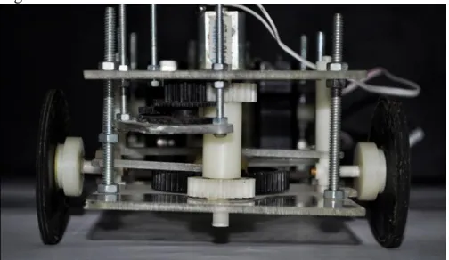
The vehicle is a laboratory made rear wheel driven car, maneuvered by two DC motors , powe red by two 4.5 vo lts Ni-MH batteries. The core structure of the vehicle was fabricated out of acrylic plates. The wheels and other additional parts were custom made. An image of the rover is shown in Fig. 2.
Sensors
The vehicle houses a cordless optical mouse that is used
as the positional feedback sensor. The advantage of an optical mouse over wheel mounted encoders is, it is not affected by wheel slip of the vehicle . The mouse wh ich is used in th is e xperiment had a 1000 dpi resolution and uses Bluetooth technology for PC to mouse communication. An LED was positioned on top of the vehicle to trace the vehic le’s travelled distance in a timed e xposed photograph which is shown in Fig. 6.
Fig. 3. Front steering system of the rover. The steering system is made out of available cogs and gears. The gears were chosen so that they perfectly meshed.
Fig. 1. Block diagram of the rover navigation and control.
Fig. 4. T he rear drive motor, belts and pulleys system and the rear wheels.
Vehicle Controller
The vehicle was remotely controlled using RF transmitter and receiver modules. In this case it was an Amplitude-shift Keying module that worked in 433M Hz frequency range. The transmitter and rece iver modules support a data transfer rate of 1k bps.
C. Position Feedback Display
To emu late the factory control panel, a PC is used as the positional display unit. It gives the current position of the vehicle. A Co mputer progra m was w ritten using C programming language to make the display. The display is the crucial part fo r controlling the AGV navigation area. It shows the current position of the AGV in real time . A co mputer program was written in C or the purpose. The program enabled the PC to trace the mouse i.e., the vehicle as fa r as it can go, of course the ma ximu m distance the vehicle could travel, was limited by the communication range of the mouse (approximately 10m in this case).
IV. EXPERIMENT S
A. Straight-Line Test
Two e xpe riments were performed to eva luate the navigation technique. One of the m was a straight-line test, in which the vehicle was positioned straight and allowed to go straight. Only the rear motor was running during this e xperiment. As gears were used in the transmission and there were no differentia l drive system associated, backlash, friction and slip are apparent in the system. To observe how the system responds to such digressions, the straight line test was carried out. In this e xperiment the vehicle was being photographed in25 seconds of timed e xposure and compared to the displayed path on the computer screen.
Fig. 5. A snap shot of the User Interface. The inner rectangle defines the test run region and the outer one defines the whole navigation area. Along x-axis each smallest unit = 6 inches and along y- axis each smallest unit = 11 inches.
Data Analysis:
After some trial, shot was taken as the carrier does not go straight due to slip, frict ion and backlash which are the common real world proble ms in robot navigation. To avoid imminent collision, the force on the ground is increased greatly by placing a PVC cover [15]. So it’s also very important to know the exact amount of vehicle slip.
Results:
An obvious comparison is shown in Fig. 6. As the car moves, the feedback fro m the positional sensor is plotted real-time. The graph is supposed to show almost a straight line as the car moves along almost straight. The figure represents slight deviation of the path along which the vehicle moves which is not a straight line. So the deviation is also
caught in the display of the system. The dark line marked as “Theoretical Navigation” is the line, the rover is supposed to move a long. Due to physical constraints like, friction, limitat ion of machin ing of driving parts the vehicle is carried away fro m its path. To ma ke the correction, it is necessary to figure out the a mount of deviation and the red line is the deviated path.
B. Turning Test:
Another e xperiment was carried out to observe the response of the system to Tu rning. As PC mice are not sensitive to the rotation along their a xes, they cannot detect turning. In the e xpe riment the position showed on the computer screen were calibrated first and then was plotted against the measured actual position.
Data Analysis:
The test was carried out twice , provid ing the steering with two different fixed angles. The deviation of the feed back fro m the actual position increased as the steering angle increased.
Results:
The deviation of the indicated value fro m the measured value is shown in Fig. 7. As in this e xperiment the prime intention was to focus on the position monitoring of the AGV and no other sensors except the optical mouse as the position sensor was used, the character of deviation is apparent in Fig. 7. Afte r applying curve fitting and Sca ling, it has been observed that both of the curves follow cubic equation. The actually travelled path follows equation no. 01 while the displayed path follows equation no. 02.
( )
( )
Fig. 7. The actual travelled path and the path plotted on the User Intefrace during a turning test is shown in the above graph. The area enclosed by x and y axis represents the navigating area.
V. DISCUSSION
A. Sensor Modification
The sensor used in this experiment was a 1000dpi resolution basic optical mouse. Among the different features of the mouse, only the image processing feature was used. These switches could be used for collision avoidance and the scroll wheel could be used to detect the relative rotation of the rear wheels with respect to each other with a slight software and hardware improvement.
To minimize e rror caused by surface roughness, using Logitech’s “Darkfield” technology as well as gaming mice could add a considerable a mount of imp rovement. A basic gaming mouse like Ra zer Abyssus can operate up to 120 in/sec ( 300c m/s) with a resolution of up to 3500 counts/in ( 1378 counts/cm) [13]. However, the development of the optics can also be a better option as it will deal with the surface roughness as well as the speed problem [16]. Th is could be done by changing the focal length of the optics.
B. Turning Improvement
This work introduces feedback to the central or loca l control of the AGV. However, the sensor used is not very sensitive to the rotation about its optical a xis. Only replace ment of the whee ls does not provide a good solution for the skid-steering proble m. The solution for a better turning detection and control, the follo wing upgrading are suggested as:
A low cost web-ca m can be used with the mouse to detect the angular displacement with respect to an illuminated point of reference on the indoor wall. Use of multip le mice than a single mouse with high
-quality programming can be a better option.
Another upgrade can be the use of a solid state rotation sensor. But, it will add up to the cost of the system.
VI. CONCLUSION
In this paper, the feasibility of using an optical mouse as a position feedback sensor for AGV control and monitoring using a simp le personal co mputer was de monstrated. The sensor used here has the precision up to 1000 dpi which is way too beyond the acceptable precision of 0.5 inch for materia l delivery vehic les. But the speed is limited by the mouse upgrade up to 30 to 38 c m/s while present technology of laser navigation which is known as the Light House Navigation operates up to a speed of 2m/s to 3m/s [9].
such that it was successfully and accurately navigated and the position was displayed in a very convenient way along a straight line. For the turning test, the technology lacks accuracy but with a little modificat ion and upgrade (as stated in the Discussion section) this technology can be a better solution for lo w cost navigation and monitoring of A GV in materia l handling system. Th is technique can be incorporated with the memorized path as well as the k inematic determination of the movement approach for control and path prediction of an Automated Guided Vehicle.
The navigation and control of indoor robots are getting more importance in the recent days because the stagnating market of industrial robot is being replaced by the use of service robots. There is an estimation wh ich states that, the total population of robots around the world will reach up to a staggering figure of 30 million by the end of 2012 [17]. As the cost for precision sensors, actuators and associated infrastructures plays a very important role in popularizing the use of robots in industries as well as households, this project shows an easy and cost effective alternative fo r indoor robot navigation. However, ma king a household service robots based on the technology stated above requires retrofitting of other low cost proximity sensors like infrared or ultrasonic range meters and a suitable structure. The use of mu ltip le optica l mouse censors with a high-quality progra mming can enable the rover to respond to the change in orientation which is usually done with the use of accelero meters and IMUs. A co mposition of pro ximity censors will do the same if developed for industrial application.
ACKNOWLEDGEMENT
The tasks were carried out under the undergraduate course of Instrumentation and Measurement, Depart ment of Mechanical Engineering, Bangladesh University of En gineering and Technology. It started in June, 2010 and finished in November, 2010. The authors would like to e xp ress their deeply gratitude to the project supervisors andMr. Abu Saleh Ahsan for their support during the project. They are very grateful to Dr. LutfaAkter, Assistant Professor, Department of Electrical and Electronic Engineering, Bangladesh University of Engineering and Technology and S. G. M. Hossain, research assistant in the Department of Mechanical Engineering, Un iversity of Nebraska Lincoln, Lincoln, NE 68503, USA for guiding to write the manuscript.
REFERENCES
[1] Swisslog , “Automatic Guided Vehicle System”, Warehouse and Distribution Solutions. Available at: www.swisslog.com
[2] R.V. Sakrikar, P.V. Sarngadharan, S. Sharma, V.K. Shrivastava,
A.P. Das, V. Dave, N. Singh, P.K. Paland Manjit Singh. “ A Material Transfer System using Automated Guided Vehicles”, Division of Remote Handling & Robotics, Technology
Development Article, BARC Newsletter, Issue No. 319 I March - April 2011.
[3] A. Sanchez, E. Aranda-Bricaire, E. G. Hernandez-Martinez, J. Magallon, J. Molina.“AGV Navigation in Flexible Manufacturing Systems using Formation Control.”Congreso Anual, 2009 de la Asociación de México de Control Automático. Zacatecas, México.
July -2009.
[4] Material Handling System, Available at: http://me.emu.edu.tr/ie447/MHS.pdf
[5] R. A. Bohlander, “ An Introduction to the T echnology of AGVs Navigation And Cont rol Systems”, Perspectives on Material Handling Practice, Promat 99 Forum – 1999.
[6] C. Wuwei, J. K. Mills & S. Wenwu, “A New Navigation Method
for an Automatic Guided Vehicle”, Journal of Robotic System s, 21(3), 129–139 (2004) © 2004 Wiley Periodicals, Inc. Published
online in Wiley Inter Science (www.interscience.wiley.com).
DOI:10.1002/rob.20004.
[7] K. Moorthy, R. L. Moorthy, W. H. Guan, “ DEADLOCK PREDICTION AND AVOIDANCE IN AN AGV SY ST EM.”
High Perform ance Computation for Engineered System s, June 30, 2000.
[8] S. Butdee,*, A. Suebsomran, F.Vignat, P.K.D.V. Yarlagadda. “Control and path predictionofan Automate Guided Vehicle”,
Journal of Achievem ents in Materialsand Manufacturing Engineering, Volume 31, Issue 2, December,2008.
[9] Jervis Webb Company, “Automatic Guided Vehicles Maximizing Productivity across Industry”, Available at: http://www.jervisbwebb.com/
[10] S. Sabikan, M. Sulaiman, Sy. Najib, Sy. Salim and M. F. Miskon, “Vision-Based Automated Guided Vehicle for Navigation and Obstacle Avoidance”, The 2nd International Conference on Engineering and ICT, February 2010, Melaka, Malaysia. [11] S. Thakoor, John M. Morookian, J. Chahl, Dean S. Hine, S.
Zornetzer. “Implementation Of An On-Chip Insect-Inspired Optic Flow Based Navigation Sensor”, NASA Tech Briefs NPO-40173, October -2005
[12] T.W. Ng, “The optical mouse as a two-dimensional displacement sensor.”Sensors and Actuators, A 107 (2003) 21–25, June-2003,
Available at: www.sciencedirect.com
[13] M. Yan, G. Szkilnyk, P. Georgas, B. W. Surgenor, “Mobile Robot Navigation with Optical Mice in a Materials Handling T ask”, 11th International Workshop on Research and Education in Mechatronic, September 9th – 10th 2010, Ostrava, Czech Republic. Available at: http://me.queensu.ca/People/Surgenor/files/REM2010opticalmice mobilerobots.pdf
[14] Savant Automation, “Frequently Asked Questions” Available at: www.agvsystems.com/faqs/q5.htm
[15] W. Travis, David M. Bevly, “Navigation Errors Introduced by Ground Vehicle Dynamics”, ION GNSS 18th International Technical Meeting of the Satellite Division, 13-16 September 2005, Long Beach, CA.
[16] C. Putnam, “Autonomous-Robot-Navigation-Using-Optical-Mouse-based-Odometry”, and October – 2004, Available at:
www.docstoc.com/docs/52704713/Autonomous-Robot-Navigation-Using-Optical-Mouse-based-Odometry.