IOSR Journal of Engineering (IOSRJEN) www.iosrjen.org ISSN (e): 2250-3021, ISSN (p): 2278-8719
Vol. 04, Issue 06 (June. 2014), ||V5|| PP 48-53
Performance comparison of power delay profile Estimation for
MIMO OFDM
Manisha K. Ahirrao, Beena R. Ballal ,Shraddha Panbude
Electronics and Telecommunication Department Vidyalankar Institute Of Technology Wadala, Dadar (w), Mumbai, India
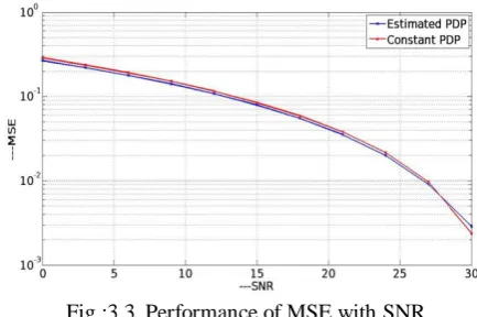
Abstract: - A multiple-input multiple-output (MIMO) communication system combined with the orthogonal frequency division multiplexing (OFDM) modulation technique can achieve reliable high data rate transmission over broadband wireless channels. In linear minimum mean square error channel (MSE) estimation for multicarrier system, it is necessary to know channel correlation function. Hence estimation of noise variance using null carrier and power delay profile can be used to approximation which can be described in two parameters like; mean delay and root mean square (RMS) delay spread. The approximate power delay profile is used to generate LMMSE coefficient for subcarrier channel estimation. In this paper the estimation of channel at pilot frequencies with Minimum Mean Square (MMSE) estimation algorithms is carried out through Mat lab simulation. The performance of MIMO OFDM is evaluated on the basis of Mean Square Error (MSE) level.Simulation results shows the performance of MSE for estimated PDP and Constant PDP for varying number of samples and for SNR. The performance of LMMSE channel estimation using the proposed PDP estimate approaches to that of Wiener filtering while in the other case, the estimated PDP gives less SNR than constant PDP.
Keywords: -Channel estimation, Power delay profile, Mean Square Error, MIMO, OFDM.
I. INTRODUCTION
Orthogonal frequency division multiplexing (OFDM) is a multi-carrier transmission technology in wireless environment, and can also be seen as a multi-carrier digital modulation or multi-carrier digital multiplexing technology [9]. The basic idea of OFDM is to divide available bandwidth into N narrow sub- channel at equidistant frequencies.[8]. A large number of orthogonal sub-carriers are used to transmit information. OFDM system has high utilization of frequency spectrum and satisfactory capability of reducing multi-path inference. So, OFDM has been considered as one of the core technologies of 4th generation (4G) wireless communication system in the future Orthogonal Frequency Division Multiplexing. [1]
A single stream of data is split into parallel streams each of which is coded and modulated on to a subcarrier, a term commonly used in OFDM systems.OFDM is a multicarrier system uses discrete Fourier Transform/Fast Fourier Transform (DFT/FFT), sin(x)/x spectra for subcarriers .Available bandwidth is divided into very many narrow bands, Data is transmitted in parallel on these bands. In OFDM each subcarrier has a different frequency, Frequencies chosen so that an integral number of cycles in a symbol period, Signals are mathematically orthogonal and Data is carried by varying the phase or amplitude of each subcarrier. Orthogonal frequency division multiplexing (OFDM) transmission scheme is another type of a multichannel system, which employs multiple subcarriers, it does not use individual band limited filters and oscillators for each sub channel and furthermore, the spectra of subcarriers are overlapped for bandwidth efficiency, The multiple orthogonal subcarrier signals, which are overlapped in spectrum, can be produced by generalizing the single-carrier In practice, discrete Fourier transform (DFT) and inverse DFT (IDFT) processes are useful for implementing these orthogonal signals. DFT and IDFT can be implemented efficiently by using fast Fourier transform (FFT) and inverse fast Fourier transform (IFFT), respectively.
Single carrier system Signal representing each bit uses the entire available spectrum. In multicarrier system available spectrum divided into many narrow bands data is divided into parallel data streams each transmitted on a separate band
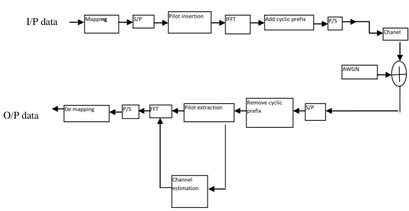
I/P data
O/P data
Fig 1: Pilot based OFDM system model.
Channel estimation plays a very important role in OFDM system .Many related algorithms have been presented these years, which can be generally separated into two methods, pilot-based channel estimation and blind channel estimation. In paper [4] the present channel estimation methods generally can be divided into two kinds: One is based on blind channel estimation which does not use pilots. Other is based on the pilots
Blind channel estimation
pilot-based channel estimation is a practical and an effective method[1]. Blind channel estimation, this uses statistical information of the received signals.Blind channel estimation methods avoid the use of pilots and have higher spectral efficiency. However, they often suffer from high computation complexity and low convergence speed since they often need a large amount of receiving data to obtain some statistical information such as cyclo stationarity induced by the cyclic prefix. Therefore, blind channel estimation methods are not suitable for applications with fast varying fading channels. And most practical communication systems such as World Interoperability for Microwave Access (WIMAX) system adopt pilot assisted channel estimation.
Pilot channel estimation
Pilot-based channel estimation estimates the channel information by obtaining the impulse response from all sub carriers by pilot. [1]
Pilot based channel estimation is based on the transmission of symbols that are known to receiver so called pilot symbols[4]. The pilot symbols are inserted into data stream and transmitted over mobile channel, at receiver pilot symbols are analyzed in order to obtain channel estimate which is utilized for equalization .As the characteristic of mobile channel is varying with time and frequency in order to obtain estimate which provides information about time and frequency domain channel variation, pilot symbol need to be transmitted periodically in time and spread over whole bandwidth which is provided for data transmission. For the pilot-aided channel estimation methods, there are two classical pilot patterns, which are the block-type pattern and the comb-type pattern. The block-type refers to that the pilots are inserted into all the subcarriers of one OFDM symbol with a certain period i.e. symbols are transmitted periodically, and all subcarriers are used as pilots.[2] The block-type can be adopted in slow fading channel, that is, the channel is stationary within a certain period of OFDM symbols. The comb-type refers to that the pilots are inserted at some specific subcarriers in each OFDM symbol. The comb-type is preferable in fast varying fading channels [7], that is, the channel varies over two adjacent OFDM symbols but remains stationary within one OFDM symbol. The comb-type pilot arrangement-based channel estimation has been shown as more applicable since it can track fast varying fading channels, compared with the block-type one.
Mapping S/P Pilot insertion IFFT Add cyclic prefix
De mapping Pilot extraction Remove cyclic prefix
Channel estimation
Chanel
AWGN P/S
S/P FFT
III. SYSTEM MODEL
The system under consideration is a MIMO-OFDM system with 𝑃 transmits and 𝑄 receive antennas, and 𝐾 total subcarriers [3].Suppose that the MIMO-OFDM system with the specified antennas transmits 𝐾𝑑 subcarriers at the central spectrum assigned for data and pilots, in order to control interferences with other systems. Let [𝑘𝑝,
𝑛𝑝] be the pilot subcarrier for the 𝑝 th transmit antenna at the 𝑛𝑝 th OFDM symbol, which is a QPSK modulated signal
Fig : 2 Pilot symbol arrangement in a block of OFDM system [3]
We assume that the pilot subcarriers are distributed over a time and frequency grid as in Fig. 2, to preserve the orthogonality of pilots among different transmits antennas. At the 𝑛𝑝 th OFDM symbol, the number of pilot subcarriers is defined as 𝐾𝑝=𝑝. The pilot inserted OFDM symbol is transmitted over the wireless channel after performing an inverse fast Fourier transform (IFFT) and adding a CP. It is assumed that the length of CP, 𝐿𝑔, is longer than the channel maximum delay, 𝐿𝑐ℎ, making the channel matrix circulate (𝐿𝑐ℎ ≤ 𝐿𝑔). At the receiver, after perfect synchronization, the removal of CP, and FFT operation, the received pilot symbol for the
𝑞 th receive antenna can be represented as, yq[np] = diag Xp Fphp,q+ nq (1)[3] where hp,q =[hp,q[np ,0],hp,q[np, 1], … ….,hp,q[npLch],0,….,0]T is an 𝐿𝑔×1 CIR vector at the 𝑝 th transmit antenna and 𝑞 th receive antenna. [3]
IV. PROPOSED METHOD FOR PDP ESTIMATION:
The proposed method is as follows:
From (1), the CIR at the (𝑝, 𝑞)th antenna port can be estimated approximately using the regularized least squares (RLS) channel estimation with a fixed length of 𝐿𝑔 as h ,R,p,q= (FpHFp+∈ ILg)−1FpHdiag(Xp)Hyq[np]
≜ WRLS ,pyq np , (2)[3] Where 𝜖 =0.001 is a small regularization parameter, and I𝐿𝑔 is the 𝐿𝑔×𝐿𝑔 identity matrix. To derive the PDP from the estimated CIR in (2), the ensemble average of h ,R,h H is given by
E{h R ,p,qh R,p,qH }=WRhhWH+σn2WRLS ,pWRLS ,pH (3)[3]
Where Rhh=E{hp,qhp,qH }and W=(FHpFp+∈ IL,g)−1FpHFp
Rℎℎ, represent the PDP of multipath channel within the length of 𝐿𝑔, Unfortunately, Rℎℎ is distorted by W, which is an ill-conditioned matrix due to the presence of F𝐻 F𝑝. Thus, instead of calculating W−1, we investigate the
method for eliminating the spectral leakage of W. The covariance matrix of the estimated CIR is defined as
Rh h = WRℎℎW𝐻 which can be expressed as
Rh h = W diag
Lg−1
l=0 (plul)W H
(4)[3] Where u𝑙 is a unit vector with the 𝑙 th entry being one and otherwise zeros. Let Ph and t𝑙 be the 𝐿𝑔×1 vectors defined as Ph= (Rh) and t𝑙=𝐷𝑔 ( W𝑑𝑖𝑎𝑔(u𝑙)W𝐻 ) , respectively, where 𝐷𝑔(A) is the column vector containing all the diagonal elements of A. Then, the relation in (4) is simplified as
Ph = p0t0+p1t1+ ⋯ . +pLg−1tLg−1≜TPh (5)[3]
PDP Estimation in MIMO-OFDM Systems
The received sample vector in (6) can be expressed as
gp,q[np]= 𝐷𝑔(hp,qhp,qH ) + n p,q+ ep,q (7)[3]
where n p,q= T−1𝐷𝑔(W𝑅𝐿𝑆,𝑝n𝑞nqH WRLS ,pH ) and
ep,q = 2 𝑅e {T−1(Whp,qnqHWRLS ,pH )}. Here, 𝑅e{a} denotes the real part of a. We assume that n p,q is an effective noise by AWGN. Then, the sample average of gp,q[np] is given by
< 𝑔p,q[np]>N ≜ 1
N gp,q[np]
Q q=1 p p=1 |Tp|
np=1 (8)[3]
= Dg hp,qhp,qH + n p,q N + ep,q N
Where 𝑁 ≜ ∣𝒯𝑝∣𝑃𝑄 represents the total number of samples for PDP estimation. ∣𝒯𝑝∣ is the number of pilot symbols at the 𝑘𝑝 th subcarrier in a time slot. When is sufficiently large, the PDP can be perfectly estimated, since Dg hp,qhp,qH N →Ph, n p ,q N →σn2w, and ep,q N → 0. However, it is difficult for a receiver of practical MIMO-OFDM systems to obtain such a large number of samples. With an insufficient number of samples, the PDP can be approximated as Ph ͌Dg hp,qhp,qH N
To improve the accuracy of PDP estimation with insufficient we mitigate the effective noise as follows
< 𝑔p,q[np]>N ‒ σn2w = Dg hp,qhp,qH + ZN, (9)[3]
where ZN ≜ ep,q N + n p,q N ‒ σn2w is defined as a residual noise vector, in which each entry has a zero-mean. Then, the error of PDP estimation with 𝑁 samples can be calculated as
eN = ( Dg hp,qhp,qH N ‒ Ph) + ZN (10)[3]
Since [Ph]i ≥ 0 for all 𝑖, the PDP can initially be estimated as
Pinit = 1
N Sp,q
|Q| q=1 |P| p=1 |Tp |
np =1 [Np] (11)[3]
where Sp,q[Np] is the sample vector of proposed PDP estimator with the 𝑙 th entry
Sp,ql [Np] = gp,q
l N
p − σn2w~1 if glp,q Np > σn2w~1
0 otherwise (12)[3]
where gp,ql Np = [gp,q[Np] ]l and w~1 = [w] To mitigate the detrimental effect of residual noise ZN, the proposed scheme estimates the average of residual noise at the zero-taps of Ph. At the l th entry of, p initthe zero-tap can be detected as
tzl = 1 if p 0 otherwiseinit < βth (13)[3]
where βth = Lg1 p initl |Lg −1|
Lg=1 is defined as a threshold value for the zero-tap detection. Then, the average of residual noise at the zero-taps can be estimated as
n Ravg = 1
Nz p init
l |Lg −1|
l=0 tzl (14)[3] where Nz=
Lg−1
l=0 t
l 𝑡𝑙 represents the total number of detected zero-taps. With the mitigation of residual noise,
the 𝑙th tap of the PDP estimate, Ph, can be expressed as
p hl
= p init −l n Ravg if p initl > n Ravg
0 therwise (15)[3]
Then, the estimated PDP in (15) can be used to obtain the frequency-domain channel correlation in the LMMSE channel estimator.
V. SIMULATION RESULTS
Fig :3.1 Performance of MSE with number of samples 500
Fig :3.2 Performance of MSE with number of samples1000
Fig :3.3 Performance of MSE with SNR
VI. CONCLUSION
REFERENCES
[1] Wang, Fei Pilot-Based Channel Estimation in OFDM System” 2011, Master of Science, University of
Toledo, Electrical Engineering
[2] Sinem Coleri, Mustafa Ergen,Anuj Puri, Ahmad Bahai “A Study of Channel Estimation in OFDM
Systems” 0-7803-7467-3/02/$17.00 ©2002 IEEE
[3] Young-Jin Kim and Gi-Hong Im, Senior Member, IEEE “Pilot-Symbol Assisted Power Delay Profile
Estimation for MIMO-OFDM Systems” Young-Jin Kim and Gi-Hong Im, Senior Member, IEEE
[4] Keshav Kumar, Amit Grover ,”Comparison of Block Type Pilot Channel Estimation Techniques for
Evaluating the performance of OFDM” International Journal of Scientific & Engineering Research”,
Volume 3, Issue 11, November-2012 ISSN 2229-5518
[5] Abdelhakim Khlifi1 and Ridha Bouallegue “Performance Analysis of LS and LMMSE Channel
Estimation Techniques for LTE Downlink Systems” International Journal of Wireless & Mobile Networks
(IJWMN) Vol. 3, No. 5, October 2011
[6] Haval Abdulrahman April 2009 , “MIMO OFDM Channel Estimation with Optimum Pilot Patterns for
Cognitive Radio in Overlay Spectrum Sharing System” , Thesis Number: IRCTR-A-009-09 Raffaello
Tesi, Matti Hämäläinen, Jari Iinatti, “CHANNEL ESTIMATION ALGORITHMS COMPARISON FOR MULTIBAND – OFDM” The 17th Annual IEEE International Symposium on Personal, Indoor and Mobile Radio Communications (PIMRC'06)
[7] Mitalee Agrawal, Yudhishthir Raut “EFFECT OF GUARD PERIOD INSERTION IN MIMO OFDM
SYSTEM” International Journal of Computer Technology and Electronics Engineering (IJCTEE) Volume
1.
[8] Kala Praveen Bagadi, Prof. Susmita Das, “MIMO-OFDM Channel Estimation using Pilot Carries”, International Journal of Computer Applications (0975 – 8887) Volume 2 – No.3, May 2010
[9] Kun-Chien Hung and David W. Lin, Senior Member, IEEE, “Pilot-Based LMMSE Channel Estimation
for OFDM Systems With Power–Delay Profile Approximation IEEE TRANSACTIONS ON
![Fig : 2 Pilot symbol arrangement in a block of OFDM system [3]](https://thumb-us.123doks.com/thumbv2/123dok_us/7832918.1667494/3.595.208.460.154.325/fig-pilot-symbol-arrangement-block-ofdm.webp)