International Journal of Research in Engineering and Science (IJRES)
ISSN (Online): 2320-9364, ISSN (Print): 2320-9356
www.ijres.org Volume 3 Issue 6 ǁ June 2015 ǁ PP.28-34
Kinematic and Dynamic Analysis of 6-UPS Parallel Robot
Xin Wang
1, Yong Xu
21(College of Mechanical Engineering, Shanghai University Of Engineering Science, China) 2(College of Mechanical Engineering, Shanghai University Of Engineering Science, China)
ABSTRACT
: Kinematics and dynamics analysis of a 6-DOF parallel robot is performed. The mechanism of this parallel robot is composed of a moving platform and a static platform, the platform are linked by 6-UPS branched chains. The position and pose of the robot moving platform are totally described by 6 variables, including 3 displacement and 3 angles of a reference point on the platform. Firstly, the constraint equations between the 6 pose parameters of the robot manipulator are deduced, and the analysis of the variables are given. Then, the dynamic equations of the parallel robot are established based on Lagrange equation. Based on this, the variations of angular velocity, driving force / torque and energy consumption of the component are analyzed by an example. The analysis is very important for the study of dynamic performance analysis, optimal design and control of the parallel mechanism.K
ey words
:Parallel manipulator; Kinematics; Dynamics; PositionI.
INTRODUCTION
The particularity of parallel robot structure makes it have the advantages which the serial robot doesn’t have,
This has caused wide attention of the international academic community. Most 6-DOF parallel robot is based on
the structure of Stewart platform, 6-DOF parallel robot has the following advantages: it can meet the needs of
most industrial operations, mechanism of the complexity and the cost is low, kinematics and dynamics model is
relatively simple, and the control is easy. Therefore, the 6-DOF parallel robot has broad application prospect.
Such as 1983, HUNT [1] proposed the 6-DOF mechanism, it gets a wide range of applications because of its two rotations and a mobile. LEE[2-3] analyzed kinematic and dynamic of 6-DOF mechanism, and they used the mechanism as the main arm of 6-DOF robot manipulator. The optimal design of kinematic for planar 6-DOF
parallel manipulator was analyzed by GOSSELIN[4].The differential kinematics of 6-DOF parallel manipulator is studied by FANG[5-6].The instantaneous motion of 6-DOF is analyzed by using the screw theory. The position of the 6-DOF mechanism based on the symmetric structure of the 6-DOF parallel robot was studied by
FANG[7-8]. Based on the relationship of system differential movement, Li Jianfeng [8] analyzed the kinematics and dynamics of the parallel mechanism of 6-DOF. The kinematics of the 6-DOF parallel robot was analyzed
by CARRETERO[9], and the parameters of the system were optimized by using the nonlinear optimization method. WANG[10]studied the static balance problem of 6-DOF parallel robot by adding weights and springs. However, the types and the number of the parallel mechanism are so much, the kinematics and dynamics of the
parallel mechanism is still insufficient.
Based on the kinematic characteristics of a space 6-DOF parallel robot the constraint equations and the pose
relationship of the parallel mechanism are analyzed and the equations of the 6 pose variables are given. The
dynamic equations of 6-DOF parallel manipulator are derived by Lagrange equation, and then the dynamic
II.
KINEMATIC ANALYSIS OF 6-DOF PARALLEL ROBOT
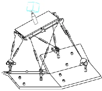
As shown in figure 1,it’s schematic diagram of a 6-DOF parallel robot. It consists of a moving platform P1P2P3, three branched BiCiPi (i=1, 2, 3) and a static platform (base) B1B2B3.the moving platform is
connected by spherical vice (S deputy) and the branch chain. The static platform is connected with each branch
by the rotating deputy (R),And the axis of the rotational pairs of Bi is parallel to the axis of Ci (i=1, 2,
3).Respectively establish local (dynamic) coordinate system Pxyz which is consolidated with the moving
platform and system (fixed) coordinate system OXYZ,As shown in Figure 1, the origin of the coordinate system
P and O are located at the geometrical center of the moving platform and the static platform, The axis Z and Z
are perpendicular to the dynamic and the static platform and they are upward, The axis X, y and X, Y are
respectively parallel and vertical the edge P2P3 and B2B3 of the upper and lower platforms. The Xi axis of local
coordinate system Bixiyizi (i=1, 2, 3) is the same to Bi rotating sub axis, Zi is vertical the static platform B1B2B3 and it’s upward, while the axis of Yi is perpendicular to the axis of Xi and Zi.
Fig. 1 Schematic diagram of 6-DOF parallel robot
The 6-DOF parallel robot moving platform and the static platform are all Squares, and the distance of the
geometrical center of the moving and static platform is l ppi =r, lOBi =R(i=1, 2, 3).then, under the system coordinate system OXYZ, coordinates of Bi (i=1, 2, 3) on the static platform are
0 2 1 2
3
0 2 1 2 3
0 0
2 2
1 R
R
B R
R
B R B
(1)
Similarly, in the local (dynamic) coordinate system Pxyz, coordinates of spherical Pi (i=1, 2, 3) in dynamic
platform are
0 2 1 2
3
0 2 1 2 3
0 0
2 2
1 r
r
p r
r
p r p
From the local dynamic coordinate system Pxyz to the system (stationary) coordinate system OXYZ. Set
transformation matrix from the local dynamic coordinate system Pxyz to the system (stationary) coordinate
system OXYZ is
1 0 0 0 p k k k p j j j p i i i Z a o n Y a o n X a o n
T (3)
Under the system coordinate system OXYZ, the coordinates of Pi (i=1, 2, 3) points in spherical hinge
center of the moving platform can be expressed as
xyz i XYZ i p T P 1 1 (4)
As the three branches B2C2P2, B3C3P3 and B1C1P1 of the parallel mechanism are respectively restricted
by the two rotating pairs. So the moving tracks of P1, P2 and P3 points in the center of the ball hinge of this
parallel robot moving platform P1P2P3 can only be located in three vertical plane, Based on these, the three
constraint equations of the system are
X Y X Y X 3 3 3 3 0 (5)
Combined (2) ~ (5) and then simplification, the constraint equations of the mechanism are
j i
i i pi
P o n o n
r Y r o
X
2
(6)
Z-Y-X Euler angle (α, β, γ) is expressed in the attitude of the mobile platform[11] P1P2P3,the type (3) can be expressed as
1 0 0 0 cos cos sin cos sin sin sin cos cos 4 2 3 1 p p p Z Y T T X T T T (7)
Combined (6) ~ (7)
cos cos cos cos sin sin sin 2 cos sin r Y r X pP (8)
arctansin sin cos cos (9)
III.
DYNAMIC ANALYSIS OF 6-DOF PARALLEL ROBOT
Set the angle between the axis OX and OBi in the 6-DOF parallel mechanism isθ0i (i=1, 2, 3). Moving
platform point Pi (i=1, 3, 2) on the coordinates in local coordinate system Pxyz are pi=(xpi ypi 0)T.Then, according to the different representations of the points Pi(i=1, 2, 3) in the coordinate system OXYZ, we can get
the formula (10) (i=1, 2, 3).
Under the system coordinate system OXYZ, the component BiCi is homogeneous in BiCiPi (i=1, 2, 3) and
the centroid coordinates is(xi1c yi1c zi1c) T,the component CiPi is homogeneous and the centroid coordinates is (xi2c yi2c zi2c) T,then
11 11 11 11 11 11 11 sin 2 1 cos 2 1 0 l z l R y x c c c (11) 12 12 11 11 12 12 12 11 11 12 12 sin 2 1 sin cos 2 1 cos 0 l l z l l R y x c c
c (12)
21 21 21 02 21 21 21 02 21 21 21 sin 2 1 sin cos 2 1 cos cos 2 1 l z l R y l R x c c c (13) 21 21 21 02 21 21 21 02 21 21 21 sin 2 1 sin cos 2 1 cos cos 2 1 l z l R y l R x c c c (14) 31 31 31 03 31 31 31 03 31 31 31 sin 2 1 sin cos 2 1 cos cos 2 1 l z l R y l R x c c c (15) 32 32 31 31 31 03 32 32 31 31 32 03 32 32 31 31 32 sin 2 1 sin sin cos 2 1 cos cos cos 2 1 cos l l z l l R y l l R x c c c (16)
The centroid speed of the component BiCi and CiPi (i=1,2,3) are respectively
v
i1
x
ijcy
ijcz
ijc
Tand
Tijc ijc ijc
i x y z
v1 ,the moment of inertia of the center of mass are recorded as Ji1 and Ji1;the inertia
matrix of the moving platform P1P2P3 relative to the Pxyz system is Ip (the inertia of the main moment of
inertia is Jx, Jy, Jz) ,the velocity and angular velocity of the moving platform are respectively
Tp p p
p X Y Z
v andwp
T.The zero potential energy surface position of gravity is taken from the plane OXY, the acceleration of gravity was g`, and the elasticity and friction of the member were not neglected.
Tp p Tp p p
i j
ij ij ijc ijc ijc
ij x y z J mv v w I w
m
T
0
3
1 2
1
2 2 2 2
2 1 2
1 (17)
p
i j
ijc
ijgz mgZ
m
V 0
3
1 2
1
(18)
Type (11) ~ (16) of t derivative, then into type (20),we can get
31 21 23 31 11 13 21 11 12 31 2 33 21 2 22 11 2 11
2
1
J J J J J J
T (19)
Substituting(18), (19) to Lagrange equation
3 , 2 , 1 1
1 1
i T
T T dt
d
i i i i
By the analysis, the energy consumption of 6-DOF parallel robot system can be expressed as
dt
E i
i i t t
f
1
3
1
0
(20)
IV.
CASE STUDY OF 6-DOF PARALLEL ROBOT
System parameters: homogeneous mechanism components are steel, the densityρ=7800kg/m3;Member length li1=li2=0.16m (i=1, 2, 3), rectangular cross section, thickness h=0.010 m, width b=0.010 m;The quality
of the mobile platform is m0=0.25kg ,Jx=0.0174 kg·m2, Jy=0.000 45 kg·m2, Jz= 0.017 9 kg·m2, r=0.10 m, R=0.12 m, t0=0 s, tf=10 s.
the law of the system is
32 32 31 31 31
03 32 32 31 31 32
03 32 32 31 31 32
sin 2 1 sin
sin cos 2 1 cos
cos cos 2 1 cos
l l
z
l l
R y
l l
R x
c c c
(21)
In the formula,
f f
f
t t t t
t t
t t
s 0
2 sin 2
1 )
(
(22)
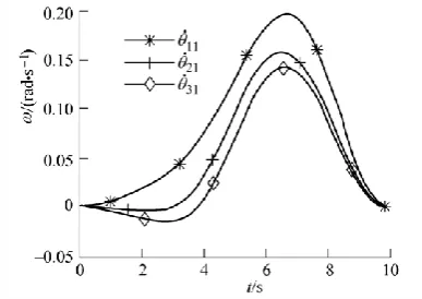
For the system given motion law, Inverse solution through system kinematics, It can be obtained from the
position of each member in this parallel mechanism. In Figure 2, the variation curves of the angular velocity of
the driving member BiCi (i=1,2,3) in the 6-DOF parallel robot are given.
Fig. 2 Driving component angular velocity curve chart
For the system given motion law, The pose and speed of motion of the 6-DOF parallel robot are changed
Fig. 3 Moving platform linear displacement and velocity curve chart
Fig. 4 Dynamic platform attitude change curve chart
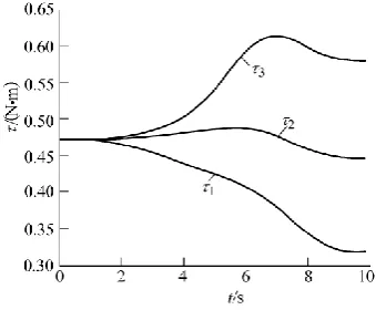
For the given motion law,the change curve of the driving moment of each active component in the system,
as shown in Figure 5.
Fig. 5 Drive torque curve chart
V.
THE ANALYSIS OF THE RESULT
(1) Zp is the only completely independent variable, It is unconnected with the other five parameters Xp、Yp、α、
β、γ.
(2) the Mechanism has 3 parameters that could be arbitrarily selected, but it must include the Zp, the other two
parameters can be arbitrarily selected.
(4) when α=0 or β=90º, Xp=0.
In this paper, the dynamic model of 6-DOF parallel robot is established by using Lagrange equation. The
pose of the system and the movement curves of the drivers are given. The change law of the driving force /
torque and energy consumption are analyzed. These contents are very important for the study of the dynamic
performance of 6-DOF robot, the optimization design of mechanism and the realization of the control law of the
system.
REFERENCE
[1] HUNT K H. Structural kinematic of in-parallel-actuated robot arms[J]. Journal of Mechanisms, Transmissions and Automation in
Design, 1983(105): 705-712.
[2] LEE K M, SHAH D K. Kinematic analysis of a three degrees-of-freedom in-parallel actuated manipulator[J]. IEEE Journal of
Robotics and Automation, 1988, 4(3): 354-360.
[3] LEE K M, SHAH D K. Dynamic analysis of a three degrees-of-freedom in-parallel actuated manipulator[J]. IEEE Journal of
Robotics and Automation, 1988, 4(3): 361-367.
[4] GOSSELIN C, ANGELES J. The optimum kinematic design of a planar three-degree-of-freedom parallel manipulator[J]. Journal
of Mechanisms, Transmissions and Automation in Design, 1988, 110(3): 35-41.
[5] FANG Yuefa, HUANG Zhen. Kinematic of a three degree- freedom in-parallel actuated manipulator mechanism[J]. Mechanism
and Machine Theory, 1997, 32(7): 789-796.
[6] HUANG Zhen, FANG Yuefa. Kinematic characteristics analysis of 3 DOF in-parallel actuated pyramid mechanisms[J].
Mechanism and Machine Theory, 1996, 31(8): 1 009-1 018.
[7] FANG Hairong, FANG Yuefa, HU Ming. Forward position analysis of a novel three DOF parallel mechanism [C]// Proceedings
of the 11th World Congress in Mechanism and Machine Science, April 1-4, 2004, Tianjin, China. Beijing:China Machinery Press,
2004: 154-157.
[8] LI Jianfeng. Cutter-path planning for surface machining and dynamic modeling of parallel machine tools [D].Beijing: Tsinghua
University, 2001.
[9] CARRETERO J A, PODHORODESKI R P, NAHON MA, et al. Kinematic analysis and optimization of a new three
degree-of-freedom spatial parallel manipulator[J].Journal of Mechanical Design, 2000, 122(3): 17-24.
[10] WANG Jiegao, GOSSELIN C M. Static salancing of spatial three-degree-of-freedom parallel mechanisms [J]. Mechanism and
Machine Theory, 1999, 34(3): 437-452.