ISSN (Online): 2320-9364, ISSN (Print): 2320-9356
www.ijres.org Volume 2 Issue 2
ǁ
Feb. 2014
ǁ
PP.48-55
Numerical Experiments of Hydrogen-Air Premixed Flames
M.A. Abdel-Raheem
1, S.S. Ibrahim
2, W. Malalasekera
11Wolfson School of Mechanical and Manufacturing Engineering, Loughborough University, UK 2
Department ofAeronautical and Automotive Engineering, Loughborough University, UK
ABSTRACT
: Numerical experiments have been carried out to study turbulent premixed flames ofhydrogen-air mixtures in a small scale combustion chamber. Flow is calculated using the Large Eddy Simulation (LES) Technique for turbulent flow. The chemical reaction is modeled using a dynamic procedure for the calculation of the flame/flow interactions. Sensitivity of the results obtained to the computational grid, ignition source and different flow configurations have been carried out. Numerical results are validated against published experimental data. It was found that the grid resolution has very small effect on the results after a certain grid. Also, the ignition source has influenced only the time where the peak overpressure appears. Finally, the different configurations are reported to affect both the peak overpressure and flame position.
Keywords
–Dynamic Flame Surface Density, Hydrogen, LES, Explosion, Reaction RateI.
INTRODUCTION
The deployment of hydrogen as a clean fuel and energy carrier brings into consideration the safety problems related to its use. The current interest in hydrogen is due its availability from many resources and the fact that has no carbon emissions. However, to enable its widespread usage in practical applications, tough challenges must be overcome regarding hydrogen and further studies are needed to develop an improved understanding of the issues affecting the generation, storage, distribution as well as combustion of hydrogen. The objective of the present work is to contribute to hydrogen safety by developing numerical capabilities to compute the overpressures resulting from itsexplosion. The study uses the large eddy simulation (LES) technique to calculate the structure of lean hydrogen flames propagating inside a vented combustion chamber while interacting with solid obstructions. The results are validated against experimental measurements reported by Masri et al. [1] and Al-Harbi et al. [2].
The LES technique is now accepted as a reliable computational tool to study turbulent flames both premixed and non-premixed [3-8] despite its added computational cost. A key advantage of LES lies in its ability to compute the complex dynamics of turbulent flows and resolve transient processes such as flame propagation, instability, extinction, as well as ignition. The cost and accuracy of LES solutions lie between direct numerical simulation (DNS) and Reynolds Averaged Navier-Stokes (RANS) techniques. A crucial challenge to the advancement of LES lies in the development of adequate sub-grid-scale (SGS) models, which are capable of representing combustion over a wide range of flow and combustion conditions. This paper makes a contribution towards this objective.
II.
R
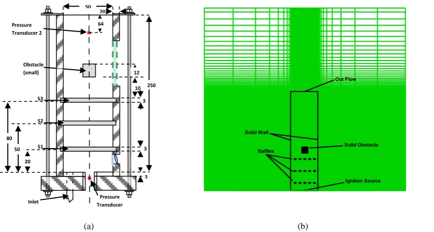
EACTION RATE CLOSUREThe experimental chamber used in this study was developed by the University of Sydney, Australia [1, 2]. The combustion chamber has dimensions of 50 x 50 x 250 mm and consists of 3 baffle plates located at equidistance and a solid square obstacle of size 12 x 12 mm at about 96 mm from the ignition end (Fig. 1a). In the experiments the hydrogen-air mixture enters the atmospheric pressure chamber, where the mixture is allowed to settle before being ignited by focusing the infrared output from a Nd:YAG laser 2 mm above the base. A hinged flap on top of the chamber contains the mixture during fill time prior to ignition. This flap is raised just before ignition and is maintained through the combustion process to allow venting.
(a) (b)
Fig. 1:(a) Schematic diagram for the Sydney combustion chamber with 3-baffles (dimensions in mm). (b) Illustration of the computational domain with the combustion chamber and the obstacles are superimposed over grid resolution.
III.
T
HE COMBUSTIONM
ODELIn LES, modelling the reaction rate in turbulent premixed flames is very challenging due to its non-linear relation with chemical and thermodynamic states. It is often characterized by propagating thin reaction sheets or layers thinner than the smallest turbulent scales. In the present simulations, the SGS chemical reaction rate is accounted for by using a recently developed DFSD model [4, 9, 10] modified for hydrogen flames.Brief details of the model are given here. More details can be found elsewhere [9].
The mean SGS chemical reaction rate ( ̇̅ ) is the source term, which is modelled by following the laminar flamelet approach as:
̇̅
̅
(1)
Where (u) is the density of unburned mixture, ( ) is the laminar burning velocity, and () is the flame surface
density (FSD). The filtered flame surface density in Eq. (1) can be split into two terms as resolved and unresolved:
̅ |
̅̅̅| ∏( ̅ ̅)
⏟
( ̅
⏟
̅ ∏( ̅ ̅))
(2)
Where ( ̅) is the mean reaction progress variable, (̅) is the filter width. The over-bar describes application of the spatial filter. The unresolved term ( ) in the above equation is evaluated using the following expression:
̅ ∏( ̅ ̅) |
̅̅̅| ∏( ̅ ̅)
(3) Baffles
Ignition Source Solid Obstacle Out Flow
Solid Wall
250
S2
3 3 3 10 12
S1 S3 Obstacle (small)
Inlet Transducer Pressure 1 Pressure
Transducer 2
50
64 20
Defining () as a ratio of test filter to grid filter, taken here equals 2 and applying the test filter (^) to flame surface density Eq. (2) leads to:
̅̂ |
̅̅̅
̂|
∏ ( ̅̂ ̅̂)
⏟
[|
⏟
̅̅̅
̂| ∏ ( ̅̂ ̅̂)]
(4)
From the above equation, the unresolved flame surface density ( ) contribution at the test filter level can be written as:
[|
̅̅̅
̂| ∏ ( ̅̂ ̅̂)]
(5)
Assuming the sub-grid scale contribution of unresolved flame surface density at test filter is the same as that at grid filter and relating () and () by using Germano identity [11]:
̂ [|
̅̅̅
̂| ∏ ( ̅̂ ̅̂)] [|
̅̅̅
̂| ∏( ̅ ̅)
̂ ]
̂ [∏( ̅ ̅)
̂ ∏ ( ̅̂ ̅̂)]
(6)
The sub-grid scale flame surface density contribution from the above equation can be added to the resolved flame surface density in Eq. (4) with a model coefficient (Cs) in order to obtain total flame surface density. Hence the flame surface density can be expressed as:
̅ ∏( ̅ ̅) [∏( ̅ ̅)
̂ ∏ ( ̅̂ ̅̂)]
(7)
The model coefficient (Cs) in above equation is dynamically obtained by identifying subgrid-scale flame surface as a fractal surface [4] as follows:
[(
̅
)
]
(8)
Where (δc) is the lower cut-off scale, (γ) is the ratio of test filter to grid filter and (D) is the fractal dimension,
calculated dynamically from [4].
(〈∏( ̅ ̅)̂ 〉 〈∏( ̅̂ ̅̂)〉⁄ )
( ̅̂ ̅⁄ )
(9)
The angular brackets ‘’ in the previous equation indicates conditional averaging within the flame bounded by ̃ = 0 to ̃ = 1.
The other parameters used in the present work are; equivalence ratio () of 0.7, a lower heating value of 286,000 (kJ/kmol) and the laminar burning velocity equals to 1.3 (m/s).The numerical model described above, has been implemented using a modified in-house LES code [12]. The details of the computational domain arepresentedin Fig. 1b. Other mathematical details of the code are not described here but available in our earlier publications [9, 10].
IV.
R
ESULTS ANDD
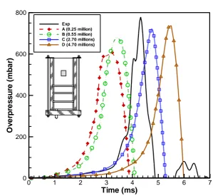
ISCUSSIONS4.1 Grid Dependence Test
grid independence and the solution convergence represent the balance between the turbulence model and reaction rate model. The other parameters for the different grids used can be found in Table 1.
Fig. 2: LES predictions of overpressure-time histories using different grid resolutions compared with experimental data.
Table 1: Numerical parameters used withthe different grid resolutions.
Parameters
A
B
C
D
Dimension 40 x 40 x 156 54 x 54 x 190 90 x 90x 336 105 x 105 x 426
Grid (in millions) 0.25 0.55 2.70 4.70
Computational Time (in days) 1 2 12 30
x (mm) 2.0 1.47 0.75 0.60
y (mm) 2.0 1.47 0.75 0.60
z (mm) 1.0 – 2.0 1.0 – 1.75 0.75 - 1.0 0.5 – 1.0
Filter Width (mm) 3.17 – 4.0 2.59 – 3.12 1.5 – 1.65 1.13 – 1.42
Flame Thickness (mm) 0.35 0.35 0.35 0.35
Grid Spacing / Filter Width 0.32 – 0.5 0.39 – 0.56 0.5 – 0.6 0.44 – 0.7
Filter Width/Flame Thickness 10.8 - 11.4 7.4 – 8.9 4.3 – 4.7 3.23 – 4.05
4.2 Ignition Radius Optimization
An optimization for the ignition source is required as there is no ignition model used in the current work. Hence, the analysis shown in Fig. 3 is used to provide the most suitable ignition radius. Itbe seen that the predicted peak overpressure is independent of the ignition radius. The only effect found is in the timing of the occurrence of the maximum pressure. The ignition radius which is found to be most appropriate to represent the early phase of flame propagation is 3 mm. Also, for the same ignition area, the shape (i.e. hemi-spherical or spherical) has no effect on either the overpressure or the timing of occurrence, as both shapes have exactly overlapped in the figure (as for 3 mm case).
Time (ms)
O
v
e
rp
re
s
s
u
re
(m
b
a
r)
0 1 2 3 4 5 6 7
0 200 400 600 800
Fig. 3: Effect of various ignition radii and shapes on overpressure-time traces for BBBS configuration (IR: Ignition Radius, H-Sph: Hemi-Spherical shape).
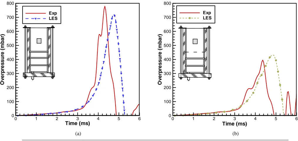
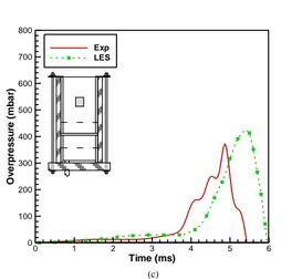
4.3 Flow Configuration Effects
In this section 3 configurations will be presented to evaluate the current model. The difference between these configurations is mainly the number and location of the baffles.For simplicity the configurations are named according to the baffles and obstacle as, the baffle by (B), the solid obstacle by (S), and location with no baffles or obstacle by (0). Hence, the cases under consideration are BBBS, BB0S and 0B0S. For configuration (BBBS), it is formed from 3 baffles located downstream of the ignition source. It can be clearly seen from Fig. 4&5 that this configuration is characterised with the highest overpressure and fastest flame speed.Where from Fig. 4a & 5a the flame in the early phase tends to be laminar even after hitting the first baffle,as its effect is not noticeable due to the closeness of this baffleto the ignition source.
Time (ms) O v e rp re s s u re (m b a r)
0 1 2 3 4 5 6 7 8 9 10
0 100 200 300 400 500 600 700 800 Exp
IR = 2.0 (H-Sph) IR = 3.0 (H-Sph) IR = 4.0 (H-Sph) IR = 5.0 (H-Sph) Spherical
(a) (b)
Time (ms) O v e rp re s s u re (m b a r)
0 1 2 3 4 5 6
0 100 200 300 400 500 600 700 800 Exp LES Time (ms) O v e rp re s s u re (m b a r)
0 1 2 3 4 5 6
Fig. 4: Overpressure-time traces of LES simulations for three configurations. (a)BBBS, (b) BB0S, and (c) 0B0S respectively compared with experimental data.
Thus this obstacle only has a small effect on turbulence generation. Actually, the main purpose of this baffle plate is just to increase the initial propagation speed of the flame front, hence leading to a faster time to peak pressure. While the second baffle (downstream of ignition source) tends increase the pressure and flame speed. The same observation could be seen in configuration (BB0S), and the trends for both configurations are almost the same until the second baffle. The third baffle (downstream of ignition source) plays the most important role in increasing the amount of turbulence generated within the combustion chamber.Highest flame accelerationoccurs after hitting this baffle and hence increasing the amount of turbulence.
Time (ms) O v e rp re s s u re (m b a r)
0 1 2 3 4 5 6
0 100 200 300 400 500 600 700 800 Exp LES (c) Time (ms) F la m e P o s it io n (m )
0 1 2 3 4 5 6
0 0.02 0.04 0.06 0.08 0.1 0.12 0.14 0.16 0.18 0.2 Exp LES Baffle 1 Baffle 2 Baffle 3 Sq. Obstacle Time (ms) F la m e P o s it io n (m )
0 1 2 3 4 5 6
0 0.02 0.04 0.06 0.08 0.1 0.12 0.14 0.16 0.18 0.2 Exp LES Baffle 1 Baffle 2 Sq. Obstacle
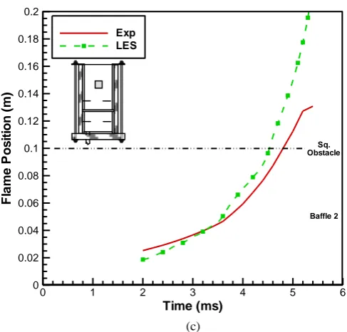
Fig. 5: Flame Position-time traces of LES simulations for three configurations. (a)BBBS, (b) BB0S, and (c) 0B0S respectively compared with experimental data.
The effect of the third baffle can be only seen for the BBBS case. The square obstacle is not a turbulence-inducing device but works to increase the blockage ratio and hence changes the development of the flame front [2, 16]. Rapid acceleration of the flame is recorded past this obstruction followed by the wrapping of the flame in the recirculation region, which enhances the mixing and distortion at the flame front [16].It should be noticed here that the discrepancies (time shift and peak overpressure) between the experimental data and the simulations could be due to many reasons. For example the ignition model, as LES combustion models based onflame surface density assume equilibrium between turbulence and flame wrinkling which is generally not reached as the flame is laminar at early stages [17].This could verify why the results for the 0B0S case have the biggest difference between the experiments and the calculations as this case tends to be more laminar.
V.
C
ONCLUSIONIn the current work the dynamic flame surface density approach has been used to model the reaction rate for hydrogen explosion inside the Sydney combustion chamber. The simulations were carried out to study the effect of grid resolution, ignition radius and different flow configurations on the current model. Based on that study the following observations have been concluded.
The grid independency has been reached after certain grid (grid C), although the solution convergence is not completely achieved after this grid.
The size and shape of the ignition radius affects only at the time shift for the peak overpressure to appear but has no effect on the value of the overpressure.
The flow configurations play an important role in the determination of the peak overpressure and flame position, and this is because as we increase the number of baffles the levels of turbulence is increased and hence the reaction rate. This leads to increase the values of the peak overpressure and flame speed as the number of baffles increase.
REFERENCES
[1] Masri, A.R., AlHarbi, A., Meares, S., and Ibrahim, S.S., A Comparative Study of Turbulent Premixed Flames Propagating Past Repeated Obstacles, Industrial and Engineering Chemistry Research, 51(22), 2011, 7690-7703.
[2] Al-Harbi, A., Masri, A.R., and Ibrahim, S.S., Turbulent Premixed Flames of CNG, LPG, and H2 Propagating Past Repeated Obstacles, 8th Mediterranean Combustion Symposium, Izmir, Turkey, 2013.
Time (ms)
F
la
m
e
P
o
s
it
io
n
(m
)
0 1 2 3 4 5 6
0 0.02 0.04 0.06 0.08 0.1 0.12 0.14 0.16 0.18 0.2
Exp LES
Sq. Obstacle
Baffle 2
[3] Charlette, F., Meneveau, C., and Veynante, D., A power-law flame wrinkling model for LES of premixed turbulent combustion Part II: dynamic formulation, Combustion and Flame, 131(1-2), 2002, 181-197.
[4] Knikker, R., Veynante, D., and Meneveau, C., A dynamic flame surface density model for large eddy simulation of turbulent premixed combustion, Physics of Fluids, 16(11), 2004, L91-L94.
[5] Fureby, C., Pitsch, H., Lipatnikov, and Hawkes, E., A fractal flame-wrinkling large eddy simulation model for premixed turbulent combustion, Proceedings of the Combustion Institute, 30(1), 2005, 593-601.
[6] Masri, A.R., Ibrahim, S.S., and Cadwallader, B.J., Measurements and large eddy simulation of propagating premixed flames, Experimental Thermal and Fluid Science, 30(7), 2006, 687-702.
[7] Pitsch, H., Large-eddy simulation of turbulent combustion, Annual Review of Fluid Mechanics, 38, 2006, 453-482.
[8] Ranga Dinesh, K.K.J., Jiang, X., Malalasekera, W., and Odedra, A., Large eddy simulation of fuel variability and flame dynamics of hydrogen-enriched nonpremixed flames, Fuel Processing Technology, 107(0), 2013, 2-13.
[9] Gubba, S.R., Ibrahim, S.S., Malalasekera, W., and Masri, A.R., "LES modelling of propagating turbulent premixed flames using a dynamic flame surface density model", 2nd ECCOMAS Thematic Conference on Computational Combustion, Delft, Netherlands, 2007.
[10] Ibrahim, S.S., Gubba, S.R., Masri, A.R., and Malalasekera, W., Calculations of explosion deflagrating flames using a dynamic flame surface density model, Journal of Loss Prevention in the Process Industries, Special Issue on CFD Simulations for Explosion Phenomena, 22, 2009, 258-264.
[11] Germano, M., Piomelli, U., Moin, P., and Cabot, W.H., A dynamic subgrid-scale eddy viscosity model, Physics of Fluids A: Fluid Dynamics, 3(7), 1991, 1760-1765.
[12] Gubba, S.R., Development of a dynamic LES model for premixed turbulent flames, PhD, Loughborough University, UK, 2009.
[13] Schumann, U., Large-eddy simulation of turbulent diffusion with chemical reactions in the convective boundary layer, Atmospheric Environment (1967), 23(8), 1989, 1713-1727.
[14] Gubba, S.R., Ibrahim, S.S., Malalasekera, W., and Masri, A.R., Measurements and LES calculations of turbulent premixed flame propagation past repeated obstacles, Combustion and Flame, 158(12), 2011, 2465-2481.
[15] Gubba, S.R., Ibrahim, S.S., Malalasekera, W., and Masri, A.R., An assessment of large eddy simulations of premixed flames propagating past repeated obstacles, Combustion Theory and Modelling, 13(3), 2009, 513-540.
[16] Abdel-Raheem, M.A., Ibrahim, S.S., Malalasekera, W., and Masri, A.R., Large Eddy Simulation of Hydrogen-Air Propagating Flames, 8th Mediterranean Combustion Symposium, Izmir, Turkey, 2013. [17] Richard, S., et al., Towards large eddy simulation of combustion in spark ignition engines, Proceedings