A Dynamic Temperature Controlling Method for
Processors in Constrained Sealed Spaces
Haixia Xia* and Yu Zhang
College of Informatics & Electronics, Zhejiang Sci-Tech University, Hangzhou, Zhejiang, 310018, China Email: [email protected], [email protected]
Abstract—Temperature is an important factor to keep the reliability of processors at run time. This paper presents a new method to perform the temperature controlling for processors working in constrained sealed device spaces. This method first models the working environment of a processor using Finite Element Analysis (FEA), and then finds the safe working frequency and the safe working time of the processor. Tasks are scheduled to work at suitable running frequencies at run time. Experimental results are as the follows: 1) The temperature of processors is higher in a constrained sealed space than that in an open space; 2) the temperature-safe running time can be obtained by temperature variation curves; and 3) the stability of systems can be kept by controlling tasks’ running speeds when using the dynamic voltage/frequency scaling (DVFS) technique.
Index Terms—Dynamic thermal management, embedded systems, constrained space, DVFS
I. INTRODUCTION
Many methods have been developed to manage and control the temperature of processors from chips’ packaging at design time to dynamic thermal management (DTM) at run time. Thermal management through packaging or active cooling at design time usually incurs expensive cost. Furthermore, some packaging methods may not be appropriate for embedded systems in some specific working environments. Due to the limitation of packaging in thermal management at design time, DTM has attracted more and more attention in managing systems’ temperature. There are the software-based and based DTM. The hardware-based DTM includes chip-wide mechanisms such as dynamic voltage and/or speed scaling [1], clock gating [2] and ILP-based techniques [3]. Recently, there have been many research efforts on the software-based DTM due to its flexibility [4]. Most of the research efforts on the software-based DTM are to reduce the temperature of processors [5-8], or optimize the running of tasks, for example, reducing the tasks’ latency [9-10], increasing the throughput of tasks [11], or minimizing the energy [12] within the temperature constraint etc. When modeling the temperature of a processor, the existing research usually uses equivalent RC circuits to model temperature in the software-based DTM. The most
widely used equation is
( ) ( ) '
( )
t t a t
th th th
P
T
T
T
C
R C
−
=
−
. (1)where T(t) is the temperature of the processor at time t, Ta
is the temperature of the ambient, P(t) is the power
consumption of the processor at time t, Rth is the thermal
resistance and Cth is the thermal capacitance of the
processor.
The equation (1) has been proved to be effective. The thermal design manuals of many processors usually provide the corresponding parameters to facilitate the modeling of the temperature of processors. If Ta is a
constant, Rth and Cth are known when a processor is
working, we can use the equation (1) to model the temperature of the processor. This is feasible when the processor is exposed in the open air or the mainframe-box of a device is much larger than its processor. However, there are many devices working in constrained spaces due to the limitation of size or working environments. For example, the automatic gear-box is an encapsulated device which is usually no more than 150mm×150mm×20mm in size. In a constrained working space, the heat dissipation of a processor is influenced not only by the air in the mainframe-box but also by the material of the mainframe-box. The latter is decided at design time and will influence the safe working of processor at run time. In this paper, we present a new modeling method for temperature of processors and a task scheduling method at run time to meet the temperature control requirements of processors.
The rest of this paper is organized as follows. Section II presents the device model and the processor model. Section III describes the basic principle of our method. Simulation experiments are given in Section IV. Finally, this paper concludes in Section V.
II. DEVICE AND PROCESSOR MODEL
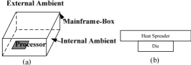
The device model used in this paper is shown in Figure 1. In Figure 1(a), the mainframe-box is a cubic container, which is made of metal material with the parameters of length L, width W, height H, and thickness TK. There is a processor in the mainframe-box, and the processor does not touch the mainframe-box. The air beyond the mainframe-box is called the external ambient, which keeps a constant temperature. The air inside the mainframe-box is called the internal ambient, which has a
Figure 1. (a) Structure of device (b) Structure of processor
variable temperature. The structure of the processor is shown in Figure 1(b), which is composed of two components, i.e., the integrated heat spreader and the die. If the processor needs to use fan cooling, there will be a fan on the heat spreader. There must be other electronic components and circuits in the printed circuit board besides the processor. For simplicity, we do not consider the influence of other components and circuits in our current research.
We assume the processor Pi has the capability of
DVFS at run time, that is to say, Pi has the parameters of
{(f1,V1),···, (fmax,Vmax)}, where fi is the operating frequency,
Vi is the supply voltage at fi, and fi < fj if i<j (it means f1 is
the minimal frequency and fmax is the maximal frequency).
We use the following equation to compute the power of the processor [13]
0 1 2
P
=
β
s
α+
β
T
+
β
. (2) where β0, β1, β2 andα
are constants, and s is the speedof the processor which is defined as [14]
2
(
dd th)
dd
V
V
s k
V
−
=
. (3)where Vdd, Vth, and k are the supply voltage, the threshold
voltage, and a hardware-specific constant respectively. In this paper, we assume the processor has a threshold temperature Tth, and errors will occur once Tth is exceeded
at run time.
III. BASIC METHODOLOGY
In order to obtain the temperature model in a constrained space, we take the following three steps. A. Modeling the Working Environment of Devices
At run time, the processor’s heat dissipating into the internal ambient is mainly constrained by air convection. The convection coefficient is influenced by the space size of the mainframe-box, and the layout of the components. Regardless of nature convection or forced ventilation, the convection effect will be weakened compared to that in the open space. In this paper, we consider both the nature convection and the forced ventilation cooling methods to suit for processors which require different cooling conditions. In the constrained space, the steady temperature in the internal ambient will be higher than that in the open space.
Because the effect of the internal ambient is to pass the heat dissipated from processors to the mainframe-box, the internal ambient is modeled as a conductor whose thermal conductivity is constrained by nature convection or forced ventilation by fans. Due to the complex influence factors, it is necessary to measure the conduction coefficient of the internal ambient by experiments using a heat source calibrated. It includes two steps. First, a series of largest temperature data can be got according to the power of the heat source, the time of the system reaching a steady state and the change of temperature of the heat source during the transient process. Second, the equivalent conduction coefficient can be deduced by using binary search. According to experience, we can assume two equivalent conduction coefficients of the internal ambient CCmin and CCmax,
which denote the possible minimal and maximal values of the equivalent conduction coefficient. Based on the data and other known parameters such as the size of mainframe-box, the material characteristic parameters (for example, density, specific heat, thermal conductivity, etc.), the temperature of external ambient, and each assuming equivalent conduction coefficient, we model the temperature curve by FEA in order to verify the consistency between the temperature curve and the measured values until the equivalent conduction coefficient is deduced.
FEA has proved its effectiveness on building temperature models of objects [15]. After obtaining the above parameters, we analyze the temperature field by the known material’s heat parameters using FEA.
B. Modeling the Safe Working Frequency
We first give the definition of the safe working frequency.
Definition 1. Safe workingfrequency is the maximal working frequency fs at which the processor could work
for infinite time while keeping its temperature below Tth.
Once the thermal parameters of the device have been obtained, we can use FEA to find the safe frequency of the processor.
C. Modeling the Safe Working Time
Definition 2. Safe workingtime is the time for which the processor could run while keeping the temperature of the processor below Tth.
We assume fs ≥ f1. It is reasonable because the
processor cannot work if fs<f1. We model the temperature
change curves from f1 to a specific frequency fi for all
f1<fi≤fmax. For example, there are four frequencies f1-f4 for
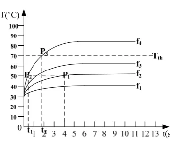
the processor, and the temperature curves are shown in Figure 2. We assume the safe working frequency of the processor is f3, and the temperature threshold is Tth, the
crossover point between Tth and the temperature curve of
Figure 2. Temperature curves
From Figure 2, we can obtain the maximal working time of the processor when its frequency changes from fi
to fj. Let’s use an example to explain its principle. In
Figure 2, at the point P1, a task τi runs at the frequency of
f2, and the temperature of the processor is 50˚C. If the
frequency of the processor is changed to f4, how long can
τi run safely? We draw a horizon line (the dash-dot line
from P1 to P2 in Figure 2), and it has a crossover point P2
with the temperature curve of f4. The time between P2 and
P3 (i.e., t2-t1) is the time for which τi can run safely. Of
course, if the frequency of the processor where τi resides
is below fs, τi can safely run for infinite time. By using
this method, we can obtain the parameters of all the temperature curves or fitting curves for a processor with DVFS capacity to direct tasks’ running. The storage of the temperature curves is a problem which should be considered carefully. The storage space for the temperature curves can be reduced due to the following facts:
z The discrete working frequencies of a processor with DVFS capability are limited. For example, there are at most seven working frequencies for a processor in Transmeta TM5800 serial [16].
z The working temperature range for electronic device usually falls between -40°C and 100°C.
z The temperature monitoring accuracy of processors is limited. For example, the on-die temperature monitoring accuracy for a processor in Transmeta TM5800 serial is ±3°C [16]. Although data presented an on-die thermal sensor which can get an accuracy of 0.2ºC in theory, its accuracy is still limited.
z The values after the stable state of a temperature curve keep constant.
Therefore, we can store finite 2-tuples {(T1, t1), (T2,
t2),··· } to denote a temperature curves. In fact, we need
only store the 2-tuples in temperature curves whose working frequencies exceed fs and temperature is below
Tth. Then the information from the temperature curves
can be used to schedule the system tasks.
D. Run-time Task Scheduling with the Temperature Constraint
Till now, many task scheduling methods in real-time fields only consider the real-time requirements [17-18]. Under the fixed priority preemptive scheduling and
temperature constraints, the running of a task depends not only on its priority, but also on whether it is likely to exceed the temperature threshold. The controlling method for the temperature of the processor presented in this paper is suitable for soft time tasks. The soft real-time tasks can exist in soft real-real-time systems or hybrid systems [19]. Because tasks may be scheduled by different algorithms to meet all kinds of requirements in different applications, we do not provide an omnipotent task scheduling method in this paper, but provide a mechanism which can be used at the release and re-scheduling instants of tasks. This mechanism only guarantees that processors will not exceed their temperature thresholds. The high-level scheduler is responsible for processing the deadline missing of tasks, and speed adjustment of the processor according to interrupts. For the processor using the DVFS technique, we assume that the task τj is preempted at the time instant
t, and a subsequent task τi has the WCET (Worst Case
Execution Time) of Ci. The current working frequency of
the processor is fi (the corresponding speed scaling factor
is Si), and the current safe working time is Δti. In this
paper, the ideal working frequency fiI is defined as the
one from the high-level schedulers where the temperature constraint is not considered, and the corresponding speed scaling factor and the corresponding safe working time are denoted as SiI and ΔtiI respectively. We modify the
task scheduling module for τi in operating systems as
follows. Run (τi) {
if (TMj exists)
Cancel the interrupt TMj which is set for the
temperature control of task τj;
if (SiCi>Δti)
Set the timer interrupt TMi at the time t+Δti;
else {
if (fi!= fiI) {
Set the working frequency of τj to the ideal
working frequency fiI;
if (SiICi>ΔtiI)
Set the timer interrupt TMi at the time t+ΔtiI;
} }
Schedule τi to run on Pi;
}
If SiCi exceeds the safe working time of Pi at the
frequency fi, the interrupt occurs to prevent the processor
from exceeding the temperature threshold. Otherwise, if the task’s frequency is modified to be not the same as the ideal working frequency fiI, its frequency is reset to fiI,
and the timer interrupt is set to tiI. Certainly, the pending
timer set for the previous running task τj should be
canceled if the actual running time of τj is less than the
safe working time of Pi, or τj is preempted by another task
before it ends.
As soon as the interrupt TMi occur, the interrupt
handler need not only save contexts but also set the working frequency of τj to fs in order to satisfy the
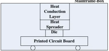
Printed Circuit Board Die Heat Spreader
Heat Conduction
Layer
Mainframe-Box
Figure 3. Structure of experiment platform
TABLE II
MATERIAL CHARACTERISTIC PARAMETERS
Component
Thermal Conductivity
(W/(m⋅°C))
Density
(kg/m3) Specific Heat(J/(kg ⋅°C))
Die 150 2330 700
Heat Spreader 237 2702 897
Mainframe-Box 237 2702 897
Heat Conduction
Layer
441.6 1.29 240
Figure 4. Surface temperature distribution of the die (a) In open space (b) In constrained space
TABLE I PROCESSOR PARAMETERS
Frequency (MHz) Maximum Power (W)
TM5800
900 6.8 867 6.5 800 6.0 700 5.3 667 5.0
IV. EXPERIMENTS
In this section, we give three simulation experiments. The influence of constrained space on the processor’s temperature, curves of working frequency and safe working time of tasks are tested. By using the proposed algorithm in this paper, results of temperature control on the processor are obtained. Although some parameters in the simulation experiments are based on assumptions, it can prove the influence of constrained space on processor temperature, and possibly direct tasks’ running. The structure of the experiment platform is shown in Figure 3. The heat conduction layer is the air layer between the heat spreader and the mainframe-box. We choose the frequency/maximum power parameters in Table I from the Transmeta TM5800 serial as the die’s power parameters. The L×W×H of the die is 8.6466mm×6.3527mm×0.818mm. The L×W×H of the heat spreader is 52mm×45mm×3.2mm. The L×W×H×TK of the mainframe-box is 120mm×100mm×10.109mm× 1mm. There is a fan on the heat spreader. We use the above parameters as the mechanical parameters of constrained space, and the parameters in Table II as the characteristic parameters of material. The temperature of the external ambient is 35°C. We ignore the influence of the printed circuit board. The tool for FEA is ANSYS 8.1.
In the following three experiments, we use ANSYS to calculate the temperature values of the die. We do not compare them with on-site measured values due to the following reasons. First, there is no suitable method to measure the runtime temperature of the die. In the existing methods, Pt-resistance thermometers may be the best option for measuring the temperature of the die in terms of response time, accuracy, range, and application fields. However, it is difficult to measure the temperature field of the die because the die is covered with the heat spreader. Although we can drill a hole in the heat spreader and put the probe of the Pt-resistance thermometers on the surface of the die, the measured temperature of the die will make a larger error because the hole on the die changes the conduction effect. Second, ANSYS has been proved to be effective software for temperature analysis. Till now, ANSYS are widely used to perform temperature analysis and optimization in the design of electromotor, electric cooker, etc. When we measure the equivalent conduction coefficients of the internal ambient, heat source is cover with sand (Sand is make of silicon, which is the same material as the surface of the die.). The probe is put in the sand and on the center of the surface of the heat spreader. Because sand is poor
conductor, the measure accuracy of the Pt-resistance thermometers can be guaranteed, and the equivalent conduction coefficients can be deduced correctly. Based on the known information, we can use ANSYS to analyze the exact temperature of the die.
In the first experiment, we compare the highest temperature of the die in an open space and in a constrained space. There are no mainframe-box and heat spreader in the open space, and the other mechanical parameters are the same as those in the constrained space. The processor power is 6.0W.
In the open space, the convection coefficient of the die and the heat spreader are determined as 7W/(m2°C) and
100W/(m2°C) respectively. In the constrained space, the
convection coefficient of the mainframe-box is 5W/(m2°C).
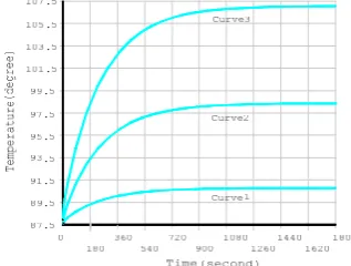
Figure 5. Temperature curves when frequencies switch
Figure 6. Temperature curve of a processor
is more difficult in the constrained space, which makes the appropriate structure design of the device and the task scheduling necessary in the constrained space. In the constrained space, it is found that the material of the mainframe-box, size, and the convection coefficient of the external ambient have more influence on the maximum temperature of the die’s surface, but the thermal conductivity of the heat conduction layer has less influence on the maximum temperature of the die’s surface even it is scaled to 1/10 times. It proves that the little error in the thermal conductivity of the heat conduction layer is acceptable.
In the second experiment, we analyze the change of the highest temperature of the die’s surface in the constrained space. In the test, the initial state of the processor is assumed to be the working frequency of 667MHz, and the processor is at the steady temperature state. Then the working frequency is switched to that of others. The results are shown in Figure 5. In Figure 5, Curve1, Curve2 and Curve3 are the temperature curves when the processor’s frequency switches from 667MHz to 700MHz, 800MHz and 900MHz, respectively. From Figure 5, we can see it usually takes several hundred seconds to reach a stable temperature when the processor carries on frequency switches. So we have enough time to change the task’s running state.
The processor’s temperature threshold is set to 91.5°C, when the temperature curve in Figure 5 is used. To analyze the change of temperature in the processor which is working in a constrained space and the software control is used to dynamic thermal control, the third experiment is performed. In this experiment, we use recurring tasks, and the number of tasks is 20. The utilization of the processor is 0.8, and the temperature of the processor is measured during a super cycle of tasks. The measured value is shown in Figure 6. In Figure 6, TC and N-TC are the temperature curves when the proposed temperature control method is and is not applied respectively. Note that we do not compare TC with other existing temperature scheduling methods because TC is not an independent scheduling method of scheduler, but a control mechanism of temperature which will be called by scheduler, as explained in Section 3.4.
When the safe working time is not used to control the processor’s temperature, it can be seen from Figure 6 that the processor’s temperature at the time instant 4, 4.5 and
5 exceed the processor’s temperature threshold due to tasks’ high speed and intensive running. This kind of overheating of processor may cause processor damage. The high speed running time of processor is under control when the proposed temperature control method in this paper is used. Although the processor’s temperature is higher at some time, the intensive area of temperature is relieved on the whole, which makes the processor’s temperature below the temperature threshold, and ensures the safety of the processor. It is noted that tasks used in the experiment have short execution time in the real-time system in order to prevent from hurting to processor, so temperature differences are not obvious. If there are tasks with long execution time, the processor’s temperature will exceed the temperature threshold significantly.
V. CONCLUSION
In the paper, a modeling method and a controlling method for the temperature problem of embedded devices in the constrained space are proposed. This method models the working environment of a processor first, and then finds the safe working frequency and the safe working time of the processor by using FEA. Under the temperature constraint, tasks are scheduled at run time by using the safe working time. The proposed method can be used to validate the design, and control the safe running of tasks in order to ensure the stability of systems.
ACKNOWLEDGMENT
This work has been supported by National Natural Science Foundation of China (No.61100183), Zhejiang Provincial Natural Science Foundation (No. Q13F020065, Y1110477 and Y1101336), and the Zhejiang Postdoctoral Research Found.
REFERENCES
[1] J.S. Lee, K. Skadron, and S.W. Chung, “Predictive
Temperature-Aware DVFS,” IEEE Transactions on
Computers, vol. 59, no. 1, pp. 7-133, 2010.
[2] S. Gunther, F. Binns, D.M. Carmean, and J.C. Hall,
“Managing the Impact of Increasing Microprocessor Power Consumption,” Intel Technology Journal, vol. Q1, pp. 1-9, 2001.
[3] S. Heo, K. Barr, and K. Asanovic, “Reducing Power
[4] Thermal-aware scheduling at the system level, http://domino.research.ibm.com/comm/research.nsf
/pages/r.os.thermal.scheduling.innovation.html.
[5] J. Chen, S. Wang, and L. Thiele, “Proactive Speed
Scheduling for Frame-Based Real-Time Tasks under Thermal Constraints,” In Proceedings of the 15th IEEE Real-Time and Embedded Technology and Applications Symposium (RTAS 2009), 2009, 141-150.
[6] X. Qin, W. Wang, and P. Mishra, “TCEC: Temperature
and Energy-Constrained Scheduling in Real-Time Multitasking Systems,” IEEE Transactions on Computer-Aided Design of Integrated Circuits and Systems, vol. 31 , no. 8, pp. 1159-1168, 2012.
[7] Y. Xie and W. Hung, “Temperature-Aware Task
Allocation and Scheduling for Embedded Multiprocessor
Systems-on-Chip (MPSoC) Design,” Journal of VLSI
Signal Processing, vol. 45, pp. 177-189, 2006.
[8] N. Fisher, J. Chen, and S. Wang, et al., “Thermal-Aware Global Real-Time Scheduling on Multicore Systems,” In Proceedings of the the 15th IEEE Real-Time and Embedded Technology and Applications Symposium (RTAS 2009), 2009, 131-140.
[9] S. Wang and R. Bettati, “Reactive speed control in
temperature-constrained real-time systems,” Real-Time Systems, vol. 39, pp. 73-95, 2008.
[10] S. Zhang and K.S. Chatha, “Approximation Algorithm for
the Temperature-aware Scheduling Problem,” In
Proceedings of the 2007 IEEE/ACM International Conference on Computer-Aided Design (ICCAD 2007), pp. 281-288, 2007.
[11] M. Chrobak, C. Durr, M. Hurand, and J. Robert,
“Algorithms for Temperature-Aware Task Scheduling in
Microprocessor Systems,” Lecture Notes in Computer
Scienc, vol. 5034, pp. 120-130, 2008.
[12] Y. Cheng, L. Zhang, Y. Han, and X. Li,
“Thermal-Constrained Task Allocation for Interconnect Energy
Reduction in 3-D Homogeneous MPSoCs,” IEEE
Transactions on Very Large Scale Integration (VLSI) Systems, vol. 21, no. 2, pp. 239-249, 2013.
[13] S. Wang, Y. Ahn, and R. Bettati, “Schedulability Analysis in Hard Real-Time Systems under Thermal Constraints,”
Real-Time Systems Journal (RTSJ), vol. 46, pp. 160-188, 2010.
[14] W. Wolf, Modern VLSI Design, Prentice Hall Modern Semiconductor Design Series, 3rd ed., Prentice Hall, USA, 2002.
[15] F. Xianzhang, C. Junwei, “Research of Distribution of Temperature Field in Process of Shaping,” Journal of Software, vol. 6, no. 1. pp. 72-77, 2011.
[16] TM5800 Data Book, version 2.1,
http://www.transmeta.com.
[17] C. Yuanlong, L. Dong, M. Peijun, “Implementation of Multi-objective Evolutionary Algorithm for Task Scheduling in Heterogeneous Distributed Systems,”
Journal of Software, vol. 7, no. 6, pp. 1367-1374, 2012. [18] Y. Nianhua, Y. Huiqun, S. Hua, Q. Zhilin, “Scheduling
Real-Time Embedded Systems Based on TCPNIA,”
Journal of Software, vol. 6, no. 3, pp. 340-348, 2011.
[19] G. Zhigang, W. Yifan, D. Guojun, and X. Haixia,
“Energy-Efficient Scheduling for Hybrid Tasks in Control Devices for the Internet of Things,” Sensors, vol. 12, no. 8, pp. 11334-11359, 2012.
Haixia Xia received the Ph.D. degree
from Zhejiang University, Hangzhou, China in 2007. She is a teacher in the College of Informatics & Electronics, Zhejiang Sci-Tech University, Hangzhou, China. Her current research interests are pervasive computing and motor systems.
Yu Zhang is an associate professor of