VOLUME 3, ISSUE 6, Jun.-2017
33 | P a g e
INVESTIGATION OF FAULT CURRENT LIMITING TRANSFORMER USING
VARIABLE REACTANCE
MR. KENDRE SOMNATH M.
ME (Power System) Scholar, Department of Electrical Engineering, GHRIET, Pune, India
PROF. LAKADE C.R.
Assistant Professor, Department of Electrical Engineering, GHRIET, Pune, India
ABSTRACT:
To demonstrate experimentally the capability of a reactive variable impedance transformer to limit the fault current and set a secondary voltage is the goal of this task. This transformer is capable of changing its leakage reactance using a shift of a mobile iron core block. It plays threerole that is voltage transformation, fault current limiting and voltage regulation. A small test device was developed and tested almost these functions. Its features should go ahead and they also explained.
KEYWORDS: Transformer, Faults, Variable Reactance, Current Limiting Transformer etc.
I.INTRODUCTION:
Our planet and our society evolve us, in many
cases, evolving ever-changing environment and
illustrations, we are forced to advance. All this comes out to fulfill the emergence of new desires emerging from this variant, global and regional trends and new technologies. What was able to come out dated as a rush, recently was contemporary. Development will change quickly need to recognize manufacturers to respond with new, advanced products. Also when applied to product care, this is mature, transformer etc. In this document, the influence on the major markets understands that the global trend is acknowledged in the era of the transformer, and currently includes innovative forerunner dry transformers and distribution, including liquid filled.
Conventionally, the transformer in power system was passive system, become active elements of the network to interact vigorously in the future, network capabilities, to ensure reliability and efficiency. In the new design specification, taking into account in the design transformer has been improved in order to strengthen regulation and stability. Current control, plays an essential role in their own industrial units, variable current transformer rating. These transformers have been distributed to the primary and secondary windings. The primary coil A, B, C is in one half of the core, a, b, c are positioned at the opposite end of the core. Another keymodification in the conventional design is a change in inductance characteristics. Leakage inductance has the
beneficial effect of limiting the transformer current without dissipating energy.
The inductance is reliant on on the geometry of the core and the windings. The change in the dispersion inductance is effected by the addition of an additional path of the flow stream between the core legs. If the 100% inductive differential transformers design, the transformer will not burn, even after a short circuit in the secondary winding. Design development approaches practically oriented as a transformer for application in which a variable current such as neon signs, gas discharge lamps, and laboratory test instruments, etc. In addition, the control arc welding sets, the average power control to motor conductors extension of electricity generating
systems and isolated connection in electrical
systemssource an increase in fault current. Although many types of fault current limiters have been proposed and some are ongoing, most only work for the current limit and the high cost and space required for their installation are difficult problems. Moreover, a certain quantity of connection, causing voltage variations in the system standard voltage distribution system power quality.
A solution in the middle of the supply line feed distribution system is the construction of a step voltage regulator (SVR), which nevertheless requires an additional cost, which does not limit the accuracy of the fault current. These problems will be avoided by the introduction of a large development and distributed generation. We propose the leakage resistance of the transformer, which can be controlled by moving the core block. A capacitor connected in parallel, consisting mainly of voltage transformation and has three functions to limit the fault current, voltage transformation, and voltage regulation. Therefore, the additional fault current limit, the consumer power system and the transformer can be replaced by a transform substation to receive and SVR. In addition, it is used to control the loop current limit fault, the expected power flow. Create a small transformer to try to improve the performance and characteristics of the experiment.
II.LITERATURE SURVEY:
VOLUME 3, ISSUE 6, Jun.-2017
34 | P a g e
investigated on transformer reactance for fault current limiting. Attest experimentally the proficiency of a transformer with variable reactance to restrict the fault current and to regulate the secondary voltage [1].
S. Blair and brilliant team investigate the future basic need to limit the fault current in the United Kingdom’s electrical system and a part of the technical implications of this change. It is expected that approximately 300-400 electrical distribution substations will be led to limit the fault current, especially in light of the static evaluation of the alleged violation of the failure level. A case study on distributed generation (DG) through a superconducting fault current limiter (SFCL) is exploited topotential guard and control problems. In particular, it addresses DG fault ride-through, auto shut-off and the current input of the adapter may be unacceptable for SFCL that need recovery period[2].
Professor KK. Kulkarni innovation introduced in the varactor transformer (Variable reactance coil) recently introduced VRT or power supplies. It has an irresistible contact between primary and secondary. Host belongs to the DC link signal line can be considered the best core saturation transformer is not the voltage control device, however, no one can get secondaryside ampere.[3].
III. PRINCIPLE:
The principles of the three tasks (voltage transformation, limiting fault current and voltage regulation) and the role of a capacitor connected in parallel are designated in this section with an equivalent circuit for this system.
A. EQUIVALENT CIRCUIT:
Fig. 1(a) EQUIVALENT CIRCUIT OF PROPOSED TRANSFORMER
REFERRED IN SECONDARY
Fig.1(a) shows the equivalent circuit of this system, which is valued in secondary side of the transformer. Turn ratio, voltage, current, resistance, and leakage reactance are denoted by a, V, I, R and X and subscripts 1 and 2 show the primary side and secondary side, respectively. Symbols in Fig. 1(b) are defined as V1r=V1/a , I1r=aI1 , Rs=R1/a2+R2, Xs=X1/a2+X2 The variable
range of the reactance Xsis represented as Xsmin≤ Xs≤ Xsmax.
Exciting circuit for the transformer is omitted from Fig. 1(a).
Fig. 1(b) VECTOR DIAGRAM FOR EQUIVALENT CIRCUIT
The relationship of each voltage vector is shown in Fig.1 (b). Impedance Zs of the transformer and transmitted
apparent power St are andimpedance angles ϕ and a
power-factor angle θ.
B. FAULT CURRENT LIMITATION:
A short-circuit in secondary side is considered and it is presumed that V2 drops to zero. In this fault situation, the
secondary current I2fc is greater than 10 pu in the case of a
conventional transformer, whose impedance ZS is set to
less than 0.1 pu in order to evade large voltage fluctuation at the normal situation. On the other hand, I2fc may be set
below a given level in the case of the transformer with variable reactance, since its minimum reactance Xsmin can
be selected much higher than ZS of a conventional
transformer because of the control function mentioned.
C. ROLE OF PARALLEL-CONNECTED CAPACITOR:
Since the current flow to a power system is delayed, a secondary V2 voltage is lower than V1R in general.
However, this can be changed to lead by connecting a capacitor with an appropriate capacity. Under this condition, V2 may be higher or lower than V1R.
IV.DESIGN METHODOLOGY:
A small trial apparatus was manufactured in order to demonstrate experimentally the functions described in Section II.
Fig.2 (a) STRUCTURE OF PROPOSED TRANSFORMER (LATERAL
VOLUME 3, ISSUE 6, Jun.-2017
35 | P a g e
Fig. 2 (b) STRUCTURE OF PROPOSED TRANSFORMER (TOP VIEW)
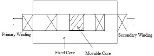
A side view of the same shown in the figure. 2 (A). The moving iron core block and the magnetic track located between the two windings. There are two air spaces between the core portion of mobile iron and the fixed iron core and the sum of them is defined as the total length (lg)
empty. When it moves to lock moving core iron core in the vertical position, as shown in Fig. 2 (a). The moving block and fixed iron core stationary in the distance. The position of the mobile block is defined as X = 0 mm when the mobile block is completely inserted in the fixed core and the total depth when the mobileblock is projected from the
fixed iron core completely. A plan view of the mobile portion of the actuator shown in the figure.2 (b).
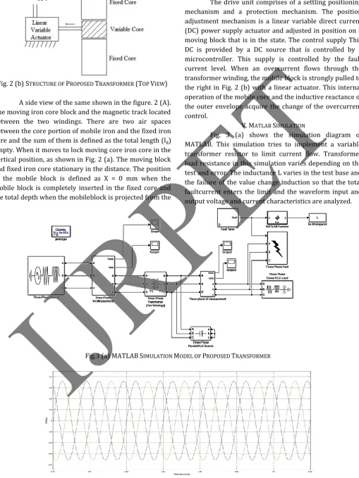
The drive unit comprises of a settling positioning mechanism and a protection mechanism. The position adjustment mechanism is a linear variable direct current (DC) power supply actuator and adjusted in position on a moving block that is in the state. The control supply This DC is provided by a DC source that is controlled by a microcontroller. This supply is controlled by the fault current level. When an overcurrent flows through the transformer winding, the mobile block is strongly pulled to the right in Fig. 2 (b) with a linear actuator. This internal operation of the mobile core and the inductive reactance of the outer envelope acquire the change of the overcurrent control.
V. MATLAB SIMULATION
Fig. 3 (a) shows the simulation diagram of MATLAB. This simulation tries to implement a variable transformer resistor to limit current flow. Transformer load resistance in this simulation varies depending on the test and error. The inductance L varies in the test base and the failure of the value change induction so that the total faultcurrent enters the limit and the waveform input and output voltage and current characteristics are analyzed.
Fig.3 (a) MATLABSIMULATION MODEL OF PROPOSED TRANSFORMER
VOLUME 3, ISSUE 6, Jun.-2017
36 | P a g e
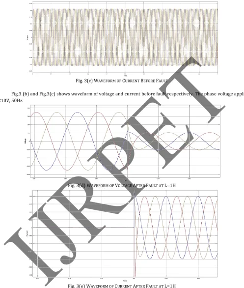
Fig. 3(c) WAVEFORM OF CURRENT BEFORE FAULT
Fig.3 (b) and Fig.3(c) shows waveform of voltage and current before fault respectively. The phase voltage applied is 210V, 50Hz.
Fig. 3(d) WAVEFORM OF VOLTAGE AFTER FAULT AT L=1H
Fig. 3(e) WAVEFORM OF CURRENT AFTER FAULT AT L=1H
VOLUME 3, ISSUE 6, Jun.-2017
37 | P a g e
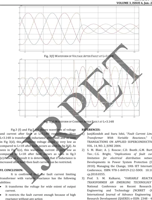
Fig. 3(f) WAVEFORM OF VOLTAGE AFTER FAULT AT L=3.14H
Fig. 3(g) WAVEFORM OF CURRENT AFTER FAULT AT L=3.14H
Fig.3 (f) and Fig.5 (g) shows waveform of voltage and current after fault at L=3.14H respectively. Here L=3.14H is transformer inductance after fault and as seen in Fig 3(d), this waveform voltage deeps is very low as compared to L=1H after fault occurs as seen in fig.3(d). As seen in Fig 5(e), this waveform current is very low as compared to L=1H after fault occurs as seen in fig.3 (e).Hence as a result it is determined that if inductance is increased after fault then fault current can be restricted.
VI. CONCLUSION:
It is confirmed that the fault current limiting transformer with variable reactance has the following abilities:
It transforms the voltage for wide extent of output current.
It restricts the fault current enough because of high reactance without any action
The voltage is regulated by the reactance adjustment.
REFERENCES:
1) JunjiKondoh and Itaru Ishii, “Fault Current Limiting Transformer With Variable Reactance,” IEEE TRANSACTIONS ON APPLIED SUPERCONDUCTIVITY, VOL. 14, NO. 2, JUNE 2004.
2) S. M. Blair; A. J. Roscoe ; C.D. Booth ; G.M. Burt ; A. Teo ; C.G. Bright, “Implications of fault current limitation for electrical distribution networks,” Developments in Power System Protection (DPSP 2010). Managing the Change, 10th IET International Conference, ISBN: 978-1-84919-212-5DOI: 10.1049/ cp.2010.0355.
3) Prof. S. M. Kulkarni, “VARIABLE REACTANCE