145004-8383-IJMME-IJENS © August 2014 IJENS I J E N S
Abstract— This paper deals with the Fuzzy-PID control on Nonlinear Wheel Balancing Robot. A simplified T-S Fuzzy-PID scheme that will be based on the signed distance method has been proposed. Simplification process of ‘conventional’ Fuzzy-PID to ‘simplified’ Fuzzy-PID scheme through 3D vector projection was demonstrated. Without reducing the performance of conventional Fuzzy-PID control, the number of fuzzy rules was greatly reduced, which eventually minimized the computational burden of the processor. Besides, the proposed controller ensures the control energy was within permissible limit and it also eliminates the effects of nonlinearity when the system was only controlled by PID controllers. Finally, the performance of proposed controller is compared to the performance of conservative Fuzzy-PID and PID schemes via simulation.
Index Term— Nonlinear Wheel Balancing Robot, Simplified Fuzzy-PID scheme, Signed distance method.
I. INTRODUCTION
NONLINEAR Wheel Balancing Robot (NWBR) is an innate unstable system. Therefore, this robot has to be continuously actuated by its motors to balance its main body from toppling. Thus, various control schemes such as linear [2-4], nonlinear [5-7], adaptive [8-10] and hybrid [11-13] controllers had been proposed to stabilize the robot. Linear control schemes had a low computational burden; however, these control signals are often much interference from disturbance and measurement noise. Moreover, its control performance degrades due to the effects of nonlinearity when NWBR is operated in larger tilt angles. In contrast, nonlinear and robust schemes are more robust to the aforementioned conditions. Thus these schemes require high computational effort from the system and they are extremely time consuming [14, 15].
As a nonlinear scheme, intelligent control scheme that is based on Fuzzy logic control (FLC) encounters similar issue [16]. Initially, one input-one output FLC controller was realized to stabilize the NWBR system [17]. Each of the input
This work was supported by Department of Higher Education of MOE Malaysia via their SLAI scheme.
M. A. Shamsudin, Rosbi Mamat and S. W. Nawawi are with Department of Control & Mechatronic Engineering, Universiti Teknologi Malaysia, 81310
Skudai, Johor, Malaysia (e-mail: [email protected], [email protected] and [email protected] ).
S. M. Ayob is with Department of Electrical Power Engineering, Universiti Teknologi Malaysia, 81310 Skudai, Johor, Malaysia (e-mail:
and output has five and seven fuzzy sets. There are some study that have considered the error and the rate of error of tilt angle as the inputs of FLC [18], and others [19, 20] that have designed this PD-Fuzzy controller as a balancing controller. Furthermore, when controlling two or more states of the NWBR system, designing sub-FLC can evade the implication of a complex FLC scheme [21]. This method diminished the required rules from 625 fuzzy rules in single FLC to 25 fuzzy rules in each of two FLCs. Further, the performance of PD-Fuzzy controller was compared to the performance of the PD controller when the centre of gravity (COG) of main body varied due to the effect of load disturbance [22]; FLC yielded faster stabilization. Alternatively, an implementation of PD-fuzzy controller and PD controller (respectively playing the role of position and balancing controllers) can reduce the computational load [23]. Meanwhile, a higher number of rules are needed to improve the control performance of the Fuzzy scheme [24], and consequently, 7 by 7 fuzzy set of rules were considered for each position FLC and balancing FLC [25]. By using incomplete rule approach, the number of rules was decreased to 35 fuzzy rules. Unfortunately, the controlled NWBR produces unexpected fluctuation and overshoot because the implemented FLCs had been realized via PI Mamdani law.
T-S Fuzzy scheme is also deployed to control NWBR. Whenever T-S fuzzy model of NWBR was available, Parallel Distributed Compensation (PDC) technique [26] could be adapted [27]. This work employed quadratic stabilization law and applied fuzzy observer to estimate the unavailable direct measure states. The inclusion of observer increased the dynamic of the system and thus producing more oscillatory state responses. In addition, the input of balancing PDC FLC can be gained by state feedback [28]. In other research, the gains were also tuned by considering LMI constrains [29]. The study conducted a comparative assessment between the controlled NWBR by LQ with linear observer, PDC FLC1 that comprising 16 T-S fuzzy models with fuzzy observer and PDC FLC2 that comprising 4T-S fuzzy model with fuzzy observer. Both PDC FLCs were more robust than the linear controller because the linear controller was unable to handle large uncertainties and the stability was lost as well. Yet, this mentioned work demonstrates PDC FLC as the only balancing controller. Again, when designing three FLCs to fully control the NWBR system, the PDC FLC was only applicable in fuzzy balanced standing control (FBSC) [30]. The other two FLCs- fuzzy travelling and position (FTPC), and fuzzy yaw steering
Simplified Partial State Fuzzy-PID Control on
Nonlinear Wheel Balancing Robot
M. A. Shamsudin*, Rosbi Mamat, S. M. Ayob and S. W. Nawawi
control (FYSC)-were realized by using 7 by 7 fuzzy PI Mamdani rules. If PDC FTPC was also realized, this second term of control disappears and only FBSC is left in operation when the main body of NWBR in vertical position. Eventually, the robot will always remain at the starting point. Thus, to realize full control of the NWBR system by using T-S Fuzzy scheme, this paper proposes simplified Fuzzy-PID scheme that is called Simplified Partial state Fuzzy-PID controller (SPS-FPID). At first, this work designs Partial state Fuzzy-PID controller (PS-FPID). Unlike conventional Fuzzy control, the proposed PS-FPID scheme takes the error, summation of error and rate of error as the inputs; hence, improves the fuzzy control performance. Furthermore, using signed distance method [31], the applied PS-FPID controller can be simplified to SPS-FPID which tremendously decreases the computational burden of the processor. Lastly, via simulation, results show the proposed controller outperforms the others equivalent controller.
II. DYNAMIC MODEL OF NWBR
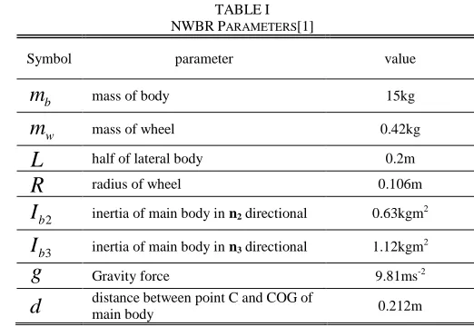
A NWBR consisted of an intermediate body, B, and two wheels, W1 and W2. Other important points to note are the COG of the main body, G, the centre of right wheel, WC1, and the centre of left wheel, WC2 where the gravitational force acts on them. Another vital point is cb where force, Fb, is exerted on the body by two wheels. Fig. 1 shows a free body diagram of the NWBR travelling from point b to c. The NWBR can be modelled by using the Newtonian approach [32], its parameters are tabulated in Table 1. Firstly, bc is defined as a linear velocity and consider following condition:
. ), ( ) ( k and j i x v t t b c c o bc c o (1)
The force and torque that are translated by the wheels to the main body at point cb are
j.R L and i R F F F w wl wr b wl wr wl wr b (2)
TheFwr, Fwl, wr and wl are the generated forces and torques by motors on the right and left wheels. The acceleration of the main body with respect to point O can be formulated as
d d
j d d
ki d d x a v r r a v dt d r dt d v dt d a bc G c G c c o G c c o c o G c c o c o G c G c c o c o G o cos sin cos sin sin cos 2 2 2 (3)
, where
v
cG
v
rx
v
ry,a
cG
d
v
cGdt
and G cr is d in vector
form. The
v
rx andv
ry are the velocityv
r inx
andy
direction respectively. The exerted force by the wheels can be solved from (4),. g m F F a
m H V b
G o b (4)
The FH and FV are experienced horizontal and vertical forces on the wheel by the main body. Based on Newton second law, the following force and torque equations are obtained: mb b g b b H b c o w w I I and F F a R I m 2 2 3 3 3 2 (5) , where 3 w I , 3 , 2,
g
and
mb
are inertia of each wheel in n3 directions, tilting angular acceleration, steering angular
acceleration, torque of main body at COG due to the gravity and yaw torque of the whole system. The following three equations of motion were obtained by appropriately solving (5) in
i
,
j
andk
vector:TABLEI
NWBRPARAMETERS[1]
Symbol parameter value
b
m
mass of body 15kgw
m
mass of wheel 0.42kgL
half of lateral body 0.2mR
radius of wheel 0.106m2
b
I
inertia of main body in n2 directional 0.63kgm23
b
I
inertia of main body in n3 directional 1.12kgm2g
Gravity force 9.81ms-2145004-8383-IJMME-IJENS © August 2014 IJENS I J E N S
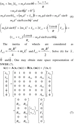
cos sin cos .cos 2 2 2 sin cos sin sin sin cos , sin cos 3 3 2 2 2 2 2 2 2 2 3 2 2 2 d m R L I R l I I L m d m and d m d m gd m I d m x d m d m R d m x m m b w wl wr w w b w b b b b b b bc b b wl wr b bc w b (6)
The inertia of wheels are considered as
2 2 2
4
L
m
R
m
I
w ww
and2
2 3R
m
I
ww
. Solve (6) forx
,
and
, One may obtain state space representation ofNWBR (7). 0 0 0 0 0 0 0 0 0 0 0 0 0 0 0 0 0 0 0 0 0 0 0 0 0 0 0 0 0 0 0 0 0 0 0 0 0 0 0 1 0 ) , ( ) ( ) , ( ) ( ) , ( ) ( 4 2 62 61 42 41 22 21 66 46 44 26 24 F F B B B B B B x x A A A A A x x t f t t t t t wl wr bc bc bc bc
A x x Bx u x
x
(7)
By linearizing NWBR and using parameters as in table 1, the following decoupled linear model of NWBR is obtained:
. 64 . 2 0 0 0 1 0 57 . 1 0 89 . 0 0 0 61 . 26 0 0 1 0 0 0 0 20 . 5 0 0 0 0 1 0 ) ( ) ( ) ( u and u x x x x t t t bc bc bc bc i i i i i
Ax Bu x
(8)
i
A
AndB
i are respectively state constant system matrix andinput matrix with appropriate dimension.
x
i
n and
iu
are respectively defined as state variables and control input withn
number of state variables. Indexi
equals to
and
to indicate balancing and steering subsystems .Theinputs of these subsystems are
wl wr
u
andu
wr
wl.III. SIMPLIFIED PARTIAL STATE FUZZY-PID A. PS-FPID
To form a hybrid FLC and PID control, FLC is firstly designed to realize linear PID control behaviour. Then FLC with three inputs, namely error
e
, change of errore
and integral of error
, are considered. Using T-S fuzzy approach, a general rule forn
inputs FLC can be realized as) (
: 1 1
x f y THEN F is x AND AND F is x IF R i i i n j n i j i
(9)
, where
i
1
,
2
,
,
m
nandm
nis the maximum number ofTHEN
IF
rules ofR
i.m
is the number of fuzzylinguistic variables of each fuzzy input variable.
x
1,
,
x
nare the antecedents of input variables in its own universe of discoursen
x x
U
U
,
,
1
.i x j n
F
| is a fuzzy set with a value ofi x j n
U
| . The output function can be formulated as thesummation of
e
,e
and
, as obtainable in a normal PID control.
i i i
i i i ii x f e e e e
f( ) ,, (10)
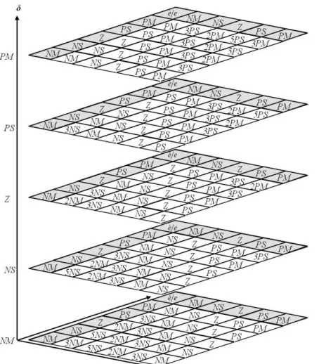
Then a rule table was established in three dimensional spaces and each fuzzy antecedent
e
,e
and
has the following fuzzy set:NM
,
NS
,
Z
,
PS
andPM
. If each of the antecedents is separated according to its neighborhood by an equal magnitude, thus the following fuzzy table as shown in Fig. 2 will be obtained. Further, to realize Fuzzy-PID control, the output function has to include PID parameters. Each of these PS-FPID controllers was illustrated as shown in Fig. 3 and its output function is
i i i
P i I i D i ii x f e e K e K K e
f( ) ,, (11)
B. SPS-FPID controller
Three dimensions Fuzzy-PID table has 125 numbers of fuzzy rules as shown in Fig. 2. It can be indicated that the rules have multiple phase–planes in the same magnitude of the fuzzy output function in the diagonal direction as shown in Fig. 4. Every point on the diagonal surface
S
i has a magnitude that is proportional to the perpendicular distance from the main diagonal surfaceS
Z. This teoplitz structure allows FLC to be reformulated in such a way the output of the FLC is in single input function that called as “signed distance”s
0
:K e K K e D
SZ P Z I Z DZ (12)
Then solving the distance by projecting
W
toV
,2 2 2
D I P
Z D Z I Z P
K K K
D e K K e K
proj d
W
V
(13)
where
V
K
PK
IK
D
Tis a normal vector to surfaceZ
S
andW
e
Z
e
P
Z
Pe
Z
e
P
Tis a vector that is pointing out fromP
ZtoQ
P. Dropping the absolute sign, this step gives the signed distanced
s. Since the main diagonal surface is parallel to its neighboring surfaces,Z D Z I Z P P D P I P
Pe K K e K e K K e
K . (14)
Simplification can be made by considering point
P
Zat theorigin, whereD0. Hence, „signed‟ distance
d
scan beobtained; where its value is positive if point
Q
Pis on the same side as the normal vectorV
and negative if it on the opposite side. The signed distanced
s isZ Di Z Ii Z Pi
s e e
d (15)
, where
2 2 2
D I P
P Pi
K K K
K
,
2 2 2
D I P
I Ii
K K K
K
and
2 2 2
D I P
D Di
K K K
K
.
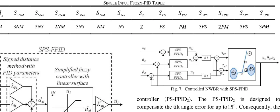
From the applied simplification method, one dimensional fuzzy table can be constructed as shown in Table 2. Thus each of the obtained SPS-FPID can be illustrated as in Fig. 6. The
controlled system of NWBR with proposed SPS-FPID controller can be shown as in Fig. 7. Therefore, a total of three numbers of SPS-FPID controller are required for NWBR system where two controllers for balancing subsystem and one controller for heading subsystem. The proposed controller is used to control actual position
x
a, tilt angle
a and headingFig. 4. Three dimensions fuzzy table with diagonal surface
Fig. 5. Patches of the diagonal surfaces
145004-8383-IJMME-IJENS © August 2014 IJENS I J E N S
angle
aof NWBR system. These controlled states need to track the desired positionx
d, tilt angle
d and heading angled
inputs trajectories. The control signals (torque) from FLC are
u u
u
u u
u
wr wr
5 . 0 5
. 0
5 . 0 5
. 0
2 1
2
1 (16)
, where
x x x e
e f
u1 1 , , , u2 f2
e,,e
andu f
e,,e
.IV. RESULT AND DISCUSSION
A. Tuning the SPS-FPID
Firstly, the gains of proposed PS-FPID controller are tuned by the quadratic regulation scheme [33] where Q and R
matrices are set to
83.112,2.548,5.229,3.466,0.001
diag
θ
Q , Rθ 1,
10,1000,10
diag
Q andR 1. Thus following PID
gains were obtained:
12.331 1.201 3.287
. 022 . 9 579 . 0 088 . 44, 015 . 3 579 . 0 879 . 1
3
PID1 PID PID1
K K K
and (17)
Further, the proposed PS-FPID has to be tuned to have similar control behaviour as PID controller. Based on the tuned gains of PS-FPID, proportional controller of KPIDθ3has the highest magnitude of gain which results in the production of highest torque energy from this controller; hence, the fuzzy Position controller (PS-FPID1) and Fuzzy steering controller
(PS-FPID3) is designed based on the design of balancing
controller (PS-FPID2). The PS-FPID2 is designed to
compensate the tilt angle error for up to 0
15 . Consequently, the initial universe of discourse of the inputs
i
e ,
i
and
i
e are from 11.54to11.54.
54 . 11 360
088 . 44 2 15 360
2 3
P
i
K e
x (18)
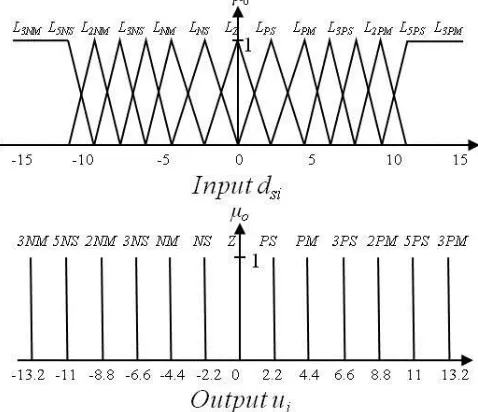
However, to ease the distribution of the membership function of each fuzzy set in equal space, the universe of discourse is set to13.2. Further, these input membership functions were realized by triangular function where each of them intersects about half of its neighborhood and the output membership functions were realized by singleton function. The value of fuzzy linguistic variable
NM,NS,Z,PS,PM
of the input is
13.2,6.6,0,6.6,13.2
and the fuzzylinguistic variable
3NM,5NS,2NM,3NS,NM,NS,Z,PS,PM,3PS,2PM,5PS,
PM
3 of the output
is
39.6,33,26.4,19.8,13.2,
6 . 39 , 33 , 4 . 26 , 8 . 19 , 2 . 13 , 6 . 6 , 0 , 6 . 6
.
Using five linguistic variables for each input, each of fuzzy position, fuzzy balancing and fuzzy steering controllers has 125 fuzzy rules. This situation will cause a high computational burden to the system. Fortunately, utilizing sign distance method, the fuzzy rules were tremendously reduced to 13 fuzzy rules as shown in Table 2. Using the same type of membership functions, both input and output membership function of SPS-FPID controller can be shown as in Fig. 8.
Result shows that the obtained SPS-FPID is linear where the rate of control action is
'
1
'
. To employ nonlinear fuzzy scheme and to improve the control performance, the fuzzy membership function is heuristically tuned by following preliminary consideration: If the error of tilt angle is less than
5
0 , the SPS-FPID has similar control action as linear PID scheme because the effect of nonlinearity is very small. If the error of tilt angle is within
5
0to15
0, the rate of control action of SPS-FPID is set to be larger than TABLEIISINGLE INPUT FUZZY-PIDTABLE
s
d
S3NM S5NS S2NM S3NS SNM SNS SZ SPS SPM S3PS S2PM S5PS S3PMu
3NM 5NS 2NM 3NS NM NS Z PS PM 3PS 2PM 5PS 3PMFig. 6. A unit of Proposed SPS-FPID.
linear control action.
If the error of tilt angle is larger than
15
0, the control action of SPS-FPID is saturated at certain value. This guarantees the SPS-FPID to produce permissible control energy (torque).Finally, the tuned membership function of SPS-FPID is shown in Fig. 9. The values of fuzzy linguistic variable
3NM,5NS,2NM,3NS,NM,NS,Z,PS,PM,3PS,2PM,4PS,
PM
3 of the input is
13.2,11,8.8,6.4,4.4,2.2,
2 . 13 , 11 , 8 . 8 , 6 . 6 , 4 . 4 , 2 . 2 ,
0 and fuzzy linguistic variable
3NM,5NS,2NM,3NS,NM,NS,Z,PS,PM,3PS,2PM,5PS
PM
3 of the output is
13.2,11,8.8,6.6,4.4,2.2,0,
2 . 13 , 11 , 8 . 8 , 6 . 6 , 4 . 4 , 2 .
2 . The fuzzy table of SPS-FPID is
shown in Table 3. The motors used in this study can generate a maximum torque of 4 Nm; therefore the real value of
1
u ,
2
u
and u in equation 16 is within ±8 Nm. Thus
m
K was set to 6
.
0 to convert the output of FLC to the mentioned real value.
B. Computation time
This subsection shows a comparison of computation time between the NWBR that is controlled by PID (16), conventional Fuzzy-PD (CFPD) [22], PS-FPID and proposed SPS-FPID. The proportional and derivative gains of CFPD were also tuned by the quadratic regulation scheme. The testing of this NWBR with the respective controller was simulated ten times for 40s in each testing. The desired
position and steering inputs were set as
) 1
( ) 3 / 5 ( )
( 0.3(t20)
d t e
x and
) 20 ( 148 . 2 )] 20 ( 2 ) ( [ 1
3 / 2 )
( 0.3( 20)
ut u t u t
e
t t
d
. Table 4 shows the computation time and its standard deviation of the system of the mentioned controller. As expected, PID had the less computational time compare to fuzzy based controller as shown in Table 4. Conventional PS-FPID had the largest computational time, which is about fifteen times more than PID controller, but the computation time of CFPD and SPS-FPID was five and four times more than PID controller respectively.
C. Stabilization performance
In this section, stabilization behavior of NWBR was investigated when non-zero initial condition and disturbance occurred on the tilt angle state. The considered initial nonzero condition of tilt angle was 0
15 and the considered disturbance
on tilt angle was 0
5 at time t50s for the duration oftDis0.5s. To show the effect of nonlinearity, the responses of linear WBR and NWBR with PID were simulated. Then, NWBR with CFPD, PS-FPID and SPS-FPID were simulated to examine their performance. Further, the tracking behaviors of NWBR that is controlled by CFPD, PS-FPID and SPS-PS-FPID were also investigated. The NWBR is required to track the position input defined by TABLEIII
SPS-FPIDTABLE
s
d
13.2 11 8.8 6.6 4.4 2.2 0 2.2 4.4 6.6 8.8 11 13.2u
13.2 11 8.8 6.6 4.4 2.2 0 2.2 4.4 6.6 8.8 11 13.2Fig. 9. The tuned input and output membership function of SPS-FPID controllers.
145004-8383-IJMME-IJENS © August 2014 IJENS I J E N S
) 1
( ) 3 / 5 ( )
( 0.3(t20)
d t e
x .
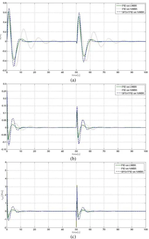
Fig. 10 shows the performance of NWBR deviated from the performance of linear WBR even it was controlled by the same PID controller. Compare to linear WBR, nonlinear NWBR took longer time to stabilize its position and tilt angle. The linear WBR generated rapid and higher torque response, but NWBR generated lower torque response. This is due to the nonlinearity factors that exist in the NWBR which degraded the performance of the system. The tuned liner PID controller has optimal performance only at equilibrium operation point; therefore, it cannot compensate this nonlinear effect when the robot is operated in larger tilt angle. As shown in Fig. 10, the performance of NWBR with SPS-FPID improved and was close to the behaviour of linear WBR. With SPS-FPID, the settling time of position and tilt angle of NWBR reduced, and the position state settled three times faster compare to the NWBR with PID controller. When large tilt angle causes the NWBR to move away from equilibrium operation point, the SPS-FPID initiates a nonlinear action to compensate; hence, it
minimizes this nonlinear effect and further improves the performance of NWBR. The implementation of SPS-FPID also confirmed that the expended torque was less than
Nm
4 when stabilizing the main body.
Fig. 11 and 12 show the behaviour of NWBR in the existence of measurement noise in the tilt angle reading. The noise was assumed to be 0
5 . 2
in magnitude and frequency of 2Hz. As shown in Fig. 11, the stabilization performance of all fuzzy based controllers was quite same, but the position response of CFPD was better. Meanwhile, Fig. 12 (a) shows that NWBR with the proposed SPS-FPID will have faster position tracking response and higher overshoot than NWBR with CFPD. Furthermore, Fig. 12 (b) shows that the NWBR with SPS-FPID will have less oscillation when stabilizing the robot as it moves to desired position. The result from both Fig. 11 and 12 showed the SPS-FPID maintained the performance of PS-FPID even when less number of fuzzy rules was implemented.
(a)
(b)
(c)
Fig. 10. Responses of (a) position (b) tilt angle and (c) torque due to the nonzero initial condition and disturbance. The solid line indicated response of LWBR that controlled by PID while the dotted and dashed lines are respectively showed the responses of NWBR that controlled PID and
SPS-FPID controllers.
(a)
(b)
(c)
Fig. 11. Responses of (a) position (b) tilt angle and (c) torque in the existence of measurement noise. The solid, dotted and dashed lines are respectively showed the responses of NWBR that controlled CFPD, PS-FPID
V. CONCLUSION
A simplified Fuzzy-PID control scheme was proposed to control NWBR system for balancing and trajectory tracking application. Using singed distance method, proposed SPS-FPID had a small number of fuzzy rules and consequently reduced the computational load of the processing system. Results showed the proposed SPS-FPID successfully maintains the performance of a complex fuzzy control scheme, eliminates the effect on nonlinearity, and guarantees the control energy within the permissible range. Lastly, in future research, the designed controller can be programmed in the embedded NWBR to realize an autonomous NWBR system.
ACKNOWLEDGMENT
This work was supported by Universiti Teknologi Malaysia and Department of Higher Education Malaysia in MOE via SLAI scholarship scheme. The authors also gratefully acknowledge the reviewers for their helpful comments and suggestions, which have improved the presentation of this paper.
REFERENCES
[1] S. W. Nawawi, "Partial Feedback Linearization Control for a Class of Two-Wheeled Mobile Robot," Phd Thesis, Universiti Teknologi Malaysia, 2010.
[2] K. M. Goher and M. O. Tokhi, "Modeling and control of a two wheeled machine: a genetic algorithm-based optimization approach," Cyber Journals: Multidisciplinary Journals in Science and Technology, Journal of Selected Areas in Robotics and Control, pp. 19-22, 2010.
[3] A. N. K. Nasir, M. A. Ahmad, and R. M. T. R. Ismail, "The control of a highly nonlinear two-wheels balancing robot: A comparative assessment between LQR and PID-PID control schemes," World Academy Of Science Engineering and Technology, vol. 46, pp. 227-232, 2010.
[4] J.-H. Han, S.-S. Zhao, J.-S. Li, and H. Li, "Research on developed parallel two-wheeled robot and its control system," in IEEE International Conference on Automation and Logistics, ICAL 2008, September 1, 2008 - September 3, 2008, Qingdao, China, 2008, pp. 2471-2475.
[5] H. Jian, G. Zhi-Hong, T. Matsuno, T. Fukuda, and K. Sekiyama, "Sliding-Mode Velocity Control of Mobile-Wheeled Inverted-Pendulum Systems," Robotics, IEEE Transactions on, vol. 26, pp. 750-758, 2010.
[6] Y. Da-Peng, Y. Jiaming, and Z. Yi-Zhang, "Control simulation for two-wheeled self-balancing robot linear move based on active disturbance rejection controller," in 2012 2nd International Conference on Intelligent Materials and Mechanical Engineering, MEE 2012, December 22, 2012 - December 23, 2012, Yichang, China, 2013, pp. 129-136.
[7] A. Shimada and N. Hatakeyama, "Movement control of two-wheeled inverted pendulum robots considering robustness," in
SICE Annual Conference 2008 - International Conference on Instrumentation, Control and Information Technology, August 20, 2008 - August 22, 2008, Tokyo, Japan, 2008, pp. 3361-3365. [8] T. Ren, T. C. Chen, and C. J. Chen, "Motion control for a
two-wheeled vehicle using a self-tuning PID controller," Control Engineering Practice, vol. 16, pp. 365-375, 2008.
[9] C.-H. Chiu, Y.-W. Lin, and C.-H. Lin, "Real-time control of a wheeled inverted pendulum based on an intelligent model free controller," Mechatronics, vol. 21, pp. 523-533, 2011.
[10] C. Li, F. Li, S. Wang, F. Dai, Y. Bai, X. Gao, et al., "Dynamic adaptive equilibrium control for a self-stabilizing robot," in 2010 IEEE International Conference on Robotics and Biomimetics, ROBIO 2010, December 14, 2010 - December 18, 2010, Tianjin, China, 2010, pp. 609-614.
[11] Y. Tanaka, Y. Ohata, T. Kawamoto, and Y. Hirata, "Adaptive control of 2-wheeled balancing robot by cerebellar neuronal network model," in 2010 32nd Annual International Conference of the IEEE Engineering in Medicine and Biology Society, EMBC'10, August 31, 2010 - September 4, 2010, Buenos Aires, Argentina, 2010, pp. 1589-1592.
[12] C. H. Chiu and C. H. Lin, "A WIP control based on an intelligent controller," World Academy Of Science Engineering and Technology vol. 54, pp. 656-661, June 2011.
[13] N. G. M. Thao, D. H. Nghia, and N. H. Phuc, "A PID backstepping controller for two-wheeled self-balancing robot," in 2010 International Forum on Strategic Technology, IFOST 2010, October 13, 2010 - October 15, 2010, Ulsan, Korea, Republic of, 2010, pp. 76-81.
[14] K.-H. Su and Y.-Y. Chen, "Balance control for two-wheeled robot via neural-fuzzy technique," in SICE Annual Conference 2010, SICE 2010, Taipei, Taiwan, 2010, pp. 2838-2842.
[15] C.-H. Chiu, "The design and implementation of a wheeled inverted pendulum using an adaptive output recurrent cerebellar model articulation controller," IEEE Transactions on Industrial Electronics, vol. 57, pp. 1814-1822, 2010.
[16] W. Wei, M. Xiaoning, and W. Jijun, "Intelligent control in two-wheel self-balanced robot," in 2010 International Conference on Computer, Mechatronics, Control and Electronic Engineering, CMCE 2010, August 24, 2010 - August 26, 2010, Changchun, China, 2010, pp. 470-473.
[17] U. Farooq, M. U. Asad, A. Hanif, K. M. Hasan, and M. Amar, "Design and implementation of a fuzzy logic controller for two wheeled self balancing robot," in 2011 7th International Conference on MEMS, NANO and Smart Systems, ICMENS 2011, November 4, 2011 - November 6, 2011, Kuala Lumpur, Malaysia, 2012, pp. 4918-4925.
[18] Y. Liao, M. Li, and C. Xu, "The design of two-wheel mobile platform using digital DC servo motor based on CompactRIO," in
2010 International Conference on Materials Science and Technology, ICMST 2010, December 27, 2010 - December 28, 2010, Jeju Island, Korea, Republic of, 2011, pp. 92-98.
[19] S. Miasa, M. Al-Mjali, A.-H. I. Anas, and T. A. Tutunji, "Fuzzy control of a two-wheel balancing robot using DSPIC," in 2010 7th
(a)
(b)
Fig. 12. Trajectory tracking responses of (a) position and (b) tilt angle in the existence of measurement noise. The solid, dotted and dashed lines are respectively showed the responses of NWBR that controlled CFPD, PS-FPID
145004-8383-IJMME-IJENS © August 2014 IJENS I J E N S International Multi-Conference on Systems, Signals and Devices,
SSD-10, June 27, 2010 - June 29, 2010, Amman, Jordan, 2010, pp. 1-6.
[20] J.-Y. Chen, T.-F. Wu, P.-S. Tsai, and K.-Y. Lian, "Indirect adaptive fuzzy controller for LEGO mindstorms NXT twowheeled robot," in 2012 International Conference on Mechatronics and Control Engineering, ICMCE 2012, November 29, 2012 - November 30, 2012, Guangzhou, China, 2013, pp. 561-567. [21] C.-H. Chiu and Y.-F. Peng, "Design and implement of the
self-dynamic controller for two-wheel transporter," in 2006 IEEE International Conference on Fuzzy Systems, July 16, 2006 - July 21, 2006, Vancouver, BC, Canada, 2006, pp. 480-483.
[22] K. M. Goher, M. O. Tokhi, and N. H. Siddique, "Dynamic modelling and control of a two wheeled robotic vehicle with a virtual payload," Journal of Engineering and Applied Sciences,
vol. 6, pp. 7-41, 2011.
[23] J. Wu and W. Zhang, "Design of fuzzy logic controller for two-wheeled self-balancing robot," in 6th International Forum on Strategic Technology, IFOST 2011, August 22, 2011 - August 24, 2011, Harbin, China, 2011, pp. 1266-1270.
[24] I. H. Altas and A. M. Sharaf, "A Generalized Direct Approach for Designing Fuzzy Logic Controllers in Matlab/Simulink GUI Environment," International Journal of Information Technology and Intelligent Computing, vol. 1, 2007.
[25] A. N. Kasruddin Nasir, M. A. Ahmad, R. Ghazali, and N. S. Pakheri, "Performance comparison between Fuzzy Logic Controller (FLC) and pid controller for a highly nonlinear two-wheels balancing robot," in 1st International Conference on Informatics and Computational Intelligence, ICI 2011, December 12, 2011 - December 13, 2011, Bandung, Indonesia, 2011, pp. 176-181.
[26] H. O. Wang, K. Tanaka, and M. Griffin, "Parallel distributed compensation of nonlinear systems by Takagi-Sugeno fuzzy model," in Fuzzy Systems, 1995. International Joint Conference of the Fourth IEEE International Conference on Fuzzy Systems and The Second International Fuzzy Engineering Symposium., Proceedings of 1995 IEEE Int, Yokohama, 1995, pp. 531-538 vol.2.
[27] H. Tirmant, M. Baloh, L. Vermeiren, T. M. Guerra, and M. Parent, "B2, an alternative two wheeled vehicle for an automated urban transportation system," in Intelligent Vehicle Symposium, 2002. IEEE, 2002, pp. 594-603 vol.2.
[28] Y. Qin, Y. Liu, X. Zang, and J. Liu, "Balance control of two-wheeled self-balancing mobile robot based on TS fuzzy model," in
6th International Forum on Strategic Technology, IFOST 2011, August 22, 2011 - August 24, 2011, Harbin, China, 2011, pp. 406-409.
[29] L. Vermeiren, A. Dequidt, T. M. Guerra, H. Rago-Tirmant, and M. Parent, "Modeling, control and experimental verification on a two-wheeled vehicle with free inclination: An urban transportation system," Control Engineering Practice, vol. 19, pp. 744-756, 2011. [30] C. H. Huang, W. J. Wang, and C. H. Chiu, "Design and implementation of fuzzy control on a two-wheel inverted pendulum," IEEE Transactions on Industrial Electronics, vol. 58, pp. 2988-3001, 2011.
[31] B.-J. Choi, S.-W. Kwak, and B. K. Kim, "Design of a single-input fuzzy logic controller and its properties," Fuzzy Sets and Systems,
vol. 106, pp. 299-308, 1999.
[32] F. Grasser, A. D‟Arrigo, S. Colombi, and A. C. Rufer, "JOE: a mobile, inverted pendulum," IEEE Transactions on Industrial Electronics, vol. 49, pp. 107-114, Feb 2002 2002.
[33] M. A. Shamsudin, R. Mamat, and S. W. Nawawi, "Dynamic Modelling and Optimal Controlscheme of Wheel Inverted Pendulum for Mobile Robot Application," International Journal of Control Theory and Computer Modeling vol. Volume 3, pp. 1-20, 2013.
Mohamad Amir Shamsudin was born in Johor, Malaysia, in 1983. He received the B.S and M.S degrees in mechatronics engineering from Universiti Teknologi Malaysia (UTM) respectively in 2007 and 2009. He is currently a PhD student in the Faculty of Electrical Engineering, UTM. His research is on Modeling and Control of Wheel Inverted Pendulum system.
Rosbi Mamat is Associate Professor at Department of Control and Mechatronic Engineering UTM, Malaysia. His research interests include control and intelligent systems, mechatronic system, and embedded system.
Shahrin Md Ayob is currently a senior lecturer at Faculty of Electrical Engineering, Universiti Teknologi Malaysia. He obtained his first degree in Electrical Engineering, Master in Electrical Engineering (Power) and Doctor of Philosophy (PhD) from Universiti Teknologi Malaysia in 2001, 2003 and 2009, respectively. His current research interest is solar photovoltaic system, electric vehicle technology, fuzzy system, and evolutionary algorithms for power electronics applications.