Study and Effects of UPFC and its Control
System for Power Flow Control and Voltage
Injection in a Power System
Vibhor Gupta
University Institute of Engineering and Technology, Panjab University, Chandigarh Contact: [email protected]
Abstract: The maintenance and reliability of the power system has become a major aspect of study. The
encouragement to the construction of HV lines, the amount of power transmission/km on HV line and the amount of power transaction as seen from economic side is much responsible for concern towards congestion in power system. The solution is the use of FACTS devices especially the use of UPFC. In this paper the study of UPFC with its various modes of operation is understood. Second, the operation of control system used in its converters is also studied. Finally by help of modeling of a power system in MATLAB, and by installing UPFC in transmission link, its use as power flow controller and voltage injection is seen. Conclusion is made on different results to see the benefit of UPFC in power system.
Keywords – FACTS, UPFC, Voltage Source Convertor, power flow controller
I. INTRODUCTION
The deregulation and competitive environment in the contemporary power networks will imply a new scenario in terms of load and power flow condition and so causing problems of line transmission capacity. But, nowadays some problems exist to change the present structure of transmission system. So, the need for new power flow controllers capable of increasing transmission capacity and controlling power flows through predefined transmission corridors [1] will certainly increase. Today’s power systems are highly complex and require careful design of new devices taking into consideration the already existing equipment, especially for transmission systems in new deregulated electricity markets. Blackouts have put network reliability on top of agenda. Improvement will require combination of technical and regulatory improvements. This is not an easy task considering that power engineers are severely limited by economic and environmental issues. Thus, this requires a review of traditional methods and the creation of new concepts that emphasize a more efficient use of already existing power system resources without reduction in system stability and security. In the late 1980s, the Electric Power Research Institute (EPRI) introduced a new approach to solve the problem of designing and operating power systems; the proposed concept is known as Flexible AC Transmission Systems (FACTS). The two main objectives of FACTS are to increase the transmission capacity and control power flow over designated transmission routes. The improvements in the field of power electronics have had major impact on the development of the concept itself. A new generation of FACTS controllers has emerged with the improvement of Gate Turn-Off (GTO) thyristor ratings (4500V to 6000V, 1000A to 6000A). These controllers [7-9] are based on voltage source converters and include devices such as Static Var Compensators (SVCs), Static Synchronous Compensators (STATCOMs), Thyristor Controlled Series Compensators (TCSCs), the Static Synchronous Series Compensators (SSSCs), and the Unified Power Flow Controller (UPFCs).
II. UNIFIED POWER FLOW CONTROLLER
A. Characteristics of UPFC
the series inverter and the transmission line. The series inverter can be used to control the real and reactive line power flow inserting an opportune voltage with controllable magnitude and phase in series with the transmission line. Thereby, the UPFC can fulfill functions of reactive shunt compensation, active and reactive series compensation and phase shifting. Besides, the UPFC allows a secondary but important function such as stability control to suppress power system oscillations improving the transient stability of power system. As the need for flexible and fast power flow controllers, such as the UPFC, is expected to grow in the future due to the changes in the electricity markets, there is a corresponding need for reliable and realistic models of these controllers to investigate the impact of them on the performance of the power system. In this article emphasis is laid to project the use of UPFC in transmission link to increase the power flow and to improve the voltage profile of the system using MATLAB SIMULINK v7.6.
B. Operation of UPFC
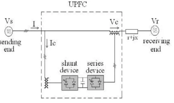
The basic components of the UPFC are two voltage source inverters (VSIs) sharing a common dc storage capacitor [6], and connected to the power system through coupling transformers. One VSI is connected to in shunt to the transmission system via a shunt transformer, while the other one is connected in series through a series transformer. A basic UPFC functional scheme is shown in fig.1.
Figure 1: UPFC Link in Transmission Line
The series inverter is controlled to inject a symmetrical three phase voltage system (Vc), of controllable magnitude and phase angle in series with the line to control active and reactive power flows on the transmission line. So, this inverter will exchange active and reactive power with the line. The reactive power is electronically provided by the series inverter, and the active power is transmitted to the dc terminals. The shunt inverter is operated in such a way as to demand this dc terminal power (positive or negative) from the line keeping the voltage across the storage capacitor Vdc constant. So, the net real power absorbed from the line by the UPFC is equal only to the losses of the inverters and their transformers. The remaining capacity of the shunt inverter can be used to exchange reactive power with the line so to provide a voltage regulation at the connection point. The two VSI’s can work independently of each other by separating the dc side. So in that case, the shunt inverter is operating as a STATCOM (Static Synchronous Compensators) that generates or absorbs reactive power to regulate the voltage magnitude at the connection point. Instead, the series inverter is operating as SSSC (Static Synchronous series compensators) that generates or absorbs reactive power to regulate the current flow, and hence the power flows on the transmission line.
C. Operating Modes of UPFC
The UPFC has many possible operating modes. In particular, the shunt inverter is operating in such a way to inject a controllable current, into the transmission line. This current consists of two components with respect to the line voltage: the real or direct component, which is in phase or in opposite phase with the line voltage, and the reactive or quadrature component, which is in quadrature. The direct component is automatically determined by the requirement to balance the real power of the series inverter. The quadrature component, instead, can be independently set to any desired reference level (inductive or capacitive) within the capability of the inverter, to absorb or generate respectively reactive power from the line. The shunt inverter can be controlled in two different modes:
VAR Control Mode: The reference input is an inductive or capacitive VAR request. The shunt inverter control
also required.
Automatic Voltage Control Mode: The shunt inverter reactive current is automatically regulated to maintain
the transmission line voltage at the point of connection to a reference value. For this mode of control, voltage feedback signals are obtained from the sending end bus feeding the shunt coupling transformer.
The series inverter controls the magnitude and angle of the voltage injected in series with the line to influence the power flow on the line. The actual value of the injected voltage can be obtained in several ways.
Direct Voltage Injection Mode: The reference inputs are directly the magnitude and phase angle of the series
voltage.
Phase Angle Shifter Emulation mode: The reference input is phase displacement between the sending end
voltage and the receiving end voltage.
Line Impedance Emulation mode: The reference input is an impedance value to insert in series with the line
impedance
Automatic Power Flow Control Mode: The reference inputs are values of P and Q to maintain on the
transmission line despite system changes. III. UPFC CONTROL SYSTEM
In order to understand the UPFC Control System the phasor diagram in the figure 2and Figure3 given below is system.
Figure2: Single-line Diagram of a UPFC
Figure3: Phasor Diagram of Voltages and Currents[3]
This FACTS topology provides much more flexibility than the SSSC for controlling the line active and reactive power because active power can now be transferred from the shunt converter to the series converter, through the DC bus. Contrary to the SSSC where the injected voltage Vs is constrained to stay in quadrature with line current I, the injected voltage Vs can now have any angle with respect to line current. If the magnitude of injected voltage Vs is kept constant and if its phase angle with respect to V1 is varied from 0 to 360 degrees, the locus described by the end of vector V2 (V2=V1+Vs) is a circle as shown on the phasor diagram. As is varying, the phase shift δ between voltages V2 and V3 at the two line ends also varies. It follows that both the active power P and the reactive power Q transmitted at one line end can be controlled.
The shunt converter operates as a STATCOM. In summary, the shunt converter controls the AC voltage at its terminals and the voltage of the DC bus. It uses a dual voltage regulation loop: an inner current control loop and an outer loop regulating AC and DC voltages.
freedom are used to control the active power and the reactive power. A simplified block diagram of the series converter is shown below Figure 4.
The series converter can operate either in power flow control (automatic mode) or in manual voltage injection mode. In power control mode, the measured active power and reactive power are compared with reference values to produce P and Q errors. The P error and the Q error are used by two PI regulators to compute respectively the Vq and Vd components of voltage to be synthesized by the VSC. (Vq in quadrature with V1controls active power and Vd in phase with V1 controls reactive power).
Figure 4: Simplified Block of the Series Converter Control System[4]
In manual voltage injection mode, regulators are not used. The reference values of injected voltage Vdref and Vqref are used to synthesize the converter voltage.
IV. MODELING OF UPFC ON A TRANSMISSION SYSTEM
Using the concept of the control system a power system is taken to implement the use of UPFC. The two modes i.e. the power flow control and the voltage injection mode are simulated in SIMULINK to see the effect of UPFC on a power system. Study is carried out to verify the utility of FACT device. The figure 5 below illustrates application study the steady-state and dynamic performance of a unified power flow controller (UPFC) used to relieve power congestion in a transmission system. The load flow analysis and the single line diagram simulation are done on power flow simulator. This software helps to calculate the power flow, the voltage at each bus and the cost effectiveness of the system
A. Explanation of Single Line Diagram
A UPFC is used to control the power flow in a 500 kV /230 kV transmission systems. The system, connected in a loop configuration, consists essentially of five buses (B1 to B5) interconnected through three transmission lines (L1, L2, L3) and two 500 kV/230 kV transformer banks Tr1 and Tr2. Two power plants located on the 230 kV system generate a total of 1500 MW (illustrated in figure 6) which is transmitted to a 500 kV, 15000 MVA equivalent and to a 200 MW load connected at bus B3. Each plant model includes a speed regulator, an excitation system as well as a power system stabilizer (PSS). In normal operation, most of the 1200 MW generation capacity of power plant #2 is exported to the 500 kV equivalents through two 400 MVA transformers connected between buses B4 and B5. For this illustration we consider a contingency case where only two transformers out of three are available (Tr2= 2*400 MVA = 800 MVA). The load flow shows that most of the power generated by plant #2 is transmitted through the 800 MVA transformer bank (899 MW out of 1000 MW) and that 96 MW is circulating in the loop. Transformer Tr2 is therefore overloaded by 99 MVA. This will now illustrate how a UPFC can relieve this power congestion. The UPFC located at the right end of line L2 is used to control the active and reactive powers at the 500 kV bus B3, as well as the voltage at bus B_UPFC. The UPFC consists of two 100 MVA, IGBT-based, converters (one shunt converter and one series converter interconnected through a DC bus). The series converter can inject a maximum of 10% of nominal line-to-ground voltage (28.87 kV) in series with line L2.
B. Model Block of Single Line Diagram
The single line diagram illustrated in Figure 5 is implemented on MATLAB SIMULINK to check the validity of the UPFC controller. The Model of UPFC will generate two kinds of results. First is based upon the simulations at power flow control mode and second on voltage injection Mode. The important keys to note in the block diagram are,
1. Use of Bypass breaker – Used to connect or disconnect UPFC Block from Power System 2. The reference power inputs [P Qref] – Reference for power flow control
3. The reference voltage Vdref – Reference for voltage injection
4. Power flow analysis at load flow indicated by arrows – Comparison with & without UPFC
C. Power Flow Control with the UPFC
Figure 6: MATLAB SIMULINK Model of the above single line diagram
D. UPFC P-Q Controllable Region and voltage injection
In the UPFC dialog box Control parameters (series converter) are seen. The mode of operation is now Manual Voltage injection. In this control mode the voltage generated by the series inverter is controlled by two external signals Vd, Vq multiplexed at the Vdqref input and generated in the Vdqref magenta block. For the first five seconds the Bypass breaker stays closed, so that the PQ trajectory stays at the (-27Mvar, 587 MW) point. Then when the breaker opens, the magnitude of the injected series voltage is ramped, from 0.0094 to 0.1 pu. At 10 s, the angle of the injected voltage starts varying at a rate of 45 deg/s.
A. SIMULATIONS
B. Power Flow Control with the UPFC
0 500 1000 1500 2000
6 6.2 6.4 6.6 6.8 7 7.2
Time (ms)
Pr
e
f U
PF
0 500 1000 1500 2000 -0.285 -0.28 -0.275 -0.27 -0.265 -0.26 Time(ms) Qr e f U P F C
0 500 1000 1500 2000
0 0.02 0.04 0.06 0.08 0.1 Time(ms) Vo lt a g e M ag (p. u) U P F C
0 500 1000 1500 2000
90 91 92 93 94 95 96 Time(ms) V o lag e pha s e(deg )
6 6.2 6.4 6.6 6.8 7 7.2
-0.274 -0.272 -0.27 -0.268 -0.266 -0.264 -0.262 -0.26
UPFC Controllable Region
0 500 1000 1500 2000 0 200 400 600 800 1000 1200 1400 Time(ms) R eal P ow er at B us es B1 B2 B3 B4 B5
C. Voltage Injection using UPFC
0 500 1000 1500 2000 2500
0 0.02 0.04 0.06 0.08 0.1 0.12 Time(ms) V ol ta ge M ag( p. u)
0 500 1000 1500 2000 2500
-200 -100 0 100 200 Time(ms) V ol tage ph as e (d eg)
4 5 6 7 8
-4 -3 -2 -1 0 1 2 3
UPFC Controllable Region
P (pu)
Q (
p
u
)
587 MW,-27 MVAr
V. RESULTS
A. Power Flow Control with UPFC
The results are in compliance with the UPFC characteristics. The net reference real power output of the UPFC increased by 100 MW when the breaker opened. The increase in the real power led to decrease in congestion on bus 5. This can be seen by the power variation at every bus in the graphs given above. Relating to the reactive power, when the breaker opened the oscillations of reactive power was finished and reactive power was then constant at -27MVAr. The main concern lies at the UPFC controllable region. The region defined in the graph is such that the UPFC can only act under these conditions; else the UPFC behaves like open to transmission link. The voltage levels were also increase so to meet the real power demand.
B. Voltage injection using UPFC
The voltage is injected by the series controller by the series transformer. The voltage is injected by increase in magnitude as well as angle to meet the characteristics as in figure 3. Considering UPFC controllable region, during this mode the results get verified in accordance with figure 3. Also the voltage level increases sharply. This shows that the voltage profile of the system has improved which increases the net power flow between transmission lines.
VI. CONCLUSION
In power system transmission, it is desirable to maintain the voltage magnitude, phase angle and line impedance. Therefore, to control the power from one end to another end, this concept of power flow control and voltage injection is applied. Modeling the system and studying the results have given an indication that UPFC are very useful when it comes to organize and maintain power system. Following conclusions are made-
1. Power flow control is achieved and congestion is less. 2. Transient stability is improved.
3. Faster Steady State achievement. 4. Improved Voltage Profile VII. REFERENCES
[1] Hingorani, N.g., “High power Electronics and Flexible AC Transmission System”, IEEE Power Eng. REV., July 1988.
[2] M. Noroozian, L. Angquist, M. Ghandhari, G. Andersson, “Use of UPFC for optimal power flow”, IEEE Transactions on Power
Delivery, vol. 12, No. 4, October 1997.
[3] Phasor Model of UPFC control, MATLAB v 7.6, ‘help’- UPFC for power flow control
[4] Control Block of UPFC - M. Toufan, U.D. Annakkage, “Simulation of The Unified Power Flow Controller Performance Using
PSCAD/EMTDC,” Electrical Power System Research Vol. 46, 1998, pp 67-75
[5] A. J. F. Keri, X. Lombard, A. A. Edris, “Unified Power Flow Controller (UPFC): Modelling and Analysis”, IEEE Trans. on Power
Delivery, Vol. 14, No. 2, April 1999, pp. 648-654.
[6] L. Xu and V.G. Agelidis, “Flying Capacitor Multilevel PWM Converter Based UPFC’, IEE Proc. Of Electronic Power Application,
Vol. 149, No. 4, July 2003. Page(s) 304-310.
[7] Narain G. Hingorani, Laszlo Gyugyi, “Understanding FACTS: Concepts and Technology of Flexible AC Transmission Systems,”
IEEE Press Marketing, 1999, pp. 297-352, pp. 407-424.
[8] C. D. Schauder, D.M. Hamai, A. Edris, “Operation of the Unified Power Controller (UPFC) under practical constraints”, IEEE
transaction on Power Delivery, vol. 13, No. 2, April 1998.
[9] I. Papic, P. Zunko, D. Povh, “Basic control of Unified Power Flow Controller ” IEEE Trans. on Power Systems, Vol. 12, No. 4,
November 1997, pp. 1734-1739.
![Figure 4: Simplified Block of the Series Converter Control System[4]](https://thumb-us.123doks.com/thumbv2/123dok_us/9603941.1488823/4.612.158.421.513.678/figure-simplified-block-series-converter-control.webp)
