EFFECT OF SOME STRUCTURAL
PARAMETERS ON THE VIBRATION OF
PRETWISTED CONICAL SHELLS – A
FINITE ELEMENT APPROACH
ANKURAN SAHA
Department of Mechanical Engineering, NIT Agartala Jirania, Tripura 799046, India
APURBA DAS
Department of Mechanical Engineering, Jadavpur University Kolkata, West Bengal 700032, India
AMIT KARMAKAR
Department of Mechanical Engineering, Jadavpur University Kolkata, West Bengal 700032, India
Abstract:
The present analysis has been carried out to study the free vibration characteristics of shallow pretwisted conical shells at static and rotational condition using finite element method. Three basic laminate formations, viz. bending stiff, torsion stiff and quasi isotropic case have been considered. An eight noded composite shell element has been considered for the present analysis. The analytical results are attained to explore the significances of skew angle, precone angle and angle of twist on the fundamental natural frequencies of undelaminated and delaminated graphite epoxy pretwisted composite conical shells. The obtained results manifests the fact that, irrespective of laminate configurations fundamental frequency attains the peak value for 00 skew angle compared to any other values of the skew angle. Maximum fundamental frequency has been
observed within a definite range of precone angle (400 to 450) regardless the effect of other parameters. Keywords:
Finite Element, Composite Laminates, Conical Shell, Skew Angle, Precone Angle, Angle of Twist.
1. Introduction
delamination model was conducted by [Krawczuk et. al, 1997] and [Shen and Grady, 1992]. Natural vibration studies of cross ply laminated composite plates and shells were carried out by [Narita et al, 1993] and [Liang et al, 2006]. [Chamis, 1977] carried out the free vibration analysis along with natural frequencies and mode shapes of composite fan blades with high tip speed for graphite fiber reinforced polyimide matrix – HTS / K601. Vibration and damping behavior of cantilever pretwisted composite blades of glass fiber reinforced plastics was conducted by [Nabi and Ganesan, 1993], wherein three nodded triangular cylindrical shell element was considered for the analysis. The effects of fiber orientation, fiber angle, skew angle, pre-twist, taper and aspect ratio on natural frequency and damping were investigated. [Todoroki et al, 2002], [Toyama et al, 2003], [Takeda and Ogihara, 1994], [Berthelot and Le Corre, 2000] and [Rebière and Gamby, 2004] have done the analytical and experimental studies of delamination initiation and growth. Considering the geometric non linearity and Coriollis acceleration term three dimensional continuum vibration analysis of rotating laminated composite blades using Ritz method and was carried out by [McGee and Chu, 1994]. Using finite element analysis, free vibration of laminated composite plates and shells was investigated by [Lee et al, 2002], [Tripathi et al, 2007] and [Aydogdu and Timarci, 2003]. [Parhi et al, 2001] carried out numerical investigation considering bending and impact using finite element method. Geometric non linearity in the form of Von Karman strains along with plain stress assumptions in the constitutive relations was considered for studying the free vibration characteristics of shear deformable, composite rotating blades by [Bhumbla, R. et.al, 1990]. [Sreenivasamurthy. S and Ramamurty. V, 1981] carried out investigation on first bending and first torsional frequencies of flat rotating low aspect ratio cantilever plates using finite element method. Triangular shell element has been considered and Coriolis Effect along with variation of skew angle, aspect ratio was also taken into account. In an important work of [Karmakar. A and Sinha. P.K, 1997], authors carried out the vibration analysis of laminated composite pretwisted cantilever plates undergoing rotations using finite element method. [Hu. X.X et al, 2003] investigated the fundamental vibration rotating cantilever blades with pre-twist. A nine noded three dimensional degenerated composite shell element has been considered and combined effect of skew and precone angle on the vibration characteristics of three basic laminate arrangements viz. bending stiff
[0 / ± 30 ] , torsion stiff [± 45/ ∓ 45 ] and quasi isotropic [0/± 45/ 90 ] . It has been observed that, most of the literatures which are available in open platforms has mainly emphasized on the vibration characteristics of uniform plates and pretwisted rotating plates by varying the structural parameters in static and dynamic state. Considering the review of the open literatures, it is revealed that there no literature available dealing with the finite element analysis of rotating laminated pretwisted conical shells considering the combined effect of skew and precone angle to analysis the free vibration characteristics of both undelaminated and delaminated bending stiff, torsion stiff and quasi isotropic laminates. Hence the present study will bridge the research gap.
1.1. Nomenclature
= Radius of curvature in x – direction
=Radius of curvature in y – direction
= Radius of Twist
= Precone Angle
= Skew Angle
= Twist Angle
Ω = Non-dimensional speed of rotation (Ω / ) Ω = Angular speed of rotation.
= Non-dimensional frequency parameter
= Mass density
= Volume
, = Length & reference width
= Poisson’s ration
ℎ, = Thickness and crack length
= Vertex Angle and base subtended angle
, = Elastic moduli along 1 and 2 axes.
, , = Shear moduli along 1 -2, 1 – 3 and 2 -3 planes
[ ] = Global mass matrix
[ ] = Shape function Matrix
[ ] = Global Coriolis Matrix
[ ], [ ], [ ] = Elastic Stiffness Matrix, geometric stiffness matrix and global rotational stiffness matrix
{ } = Global displacement vector
= Non-dimensional frequency
, ,, ,= Nodal displacements
, = Rotation about x and y axis.
{ } = Transverse shear resultants
[ ] = Extension coefficient
[ ] = Bending extension coupling coefficients
[ ] = Bending stiffness coefficients
{ } = Strain vector
= z-co-ordinate of mid plane of tth sublaminate , = Local natural coordinates of the element
, , = Local coordinate axes
, , = Inertial coordinate axes
, , = Fixed translational offsets of the plate coordinate axes from inertial axes.
/ = Aspect ratio
= Natural frequency of the rotating shell
2. Theoretical Formulations
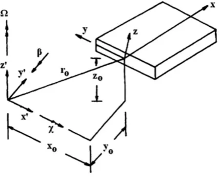
Two coordinate system (x0, y0, z0) and (x, y, z) are used for modeling the rotating plate Fig. 1 where (x0, y0, z0)
is the inertial reference frame (absolute fixed system) and (x, y, z) is the plate coordinate system (local coordinate axes). The local kinetic energy of the rotating plate can be expressed as
= 1
2 (1)
Where the absolute velocity vector of an arbitrary point on the plate with respect to inertial reference frame (x’, y’, z’) is . The plate is assumed to rotate about the inertial coordinate system (x, y, z) with an angular velocity component Ω = Ω about the axis.
Fig 1. Rotational and Translational offsets of the rotating plate local axes from the inertial axes
With respect to the plate coordinate system the angular velocity components are given in Fig. 1.
Ω , Ω , Ω = {0 , 0 , Ω} [ ] (2) In which,
= 10 cos0 − sin0
0 sin cos (3)
[ ] = cos0 0 − sin1 0
sin 0 cos (4)
Where the rotational speed of the plate about axis of the inertial coordinate system (x’, y’, z’) is Ω. is the skew angle and is the precone angle. With reference to plate coordinate system, the fixed translational offsets expressed as,
ℎ , ℎ , ℎ = { , , } [ ] (5)
According to Chasle’s theorem:
= + (Ω ) (6)
= (ℎ + + ) + ℎ + + + (ℎ + + ) (7)
The angular velocity vector can be written as
Ω = Ω = Ω + Ω + Ω (8)
The velocity vector is given by
= + Ω (ℎ + + ) − Ω ℎ + + + [ + Ω (ℎ + + ) − Ω (ℎ + + )]
+ + Ω ℎ + + − Ω (ℎ + + ) (9)
The kinetic energy expression can be written after computing the value of ∙ = and neglecting the noncontributing terms in Lagrange’s equation.
Kinetic Energy,
= 1
2 [ ][ ] +
1
2 [ ][ ][ ]
+1
2 [ ][ ][ ]
+1
2 (ℎ + ) ℎ + (ℎ + )[ ][ ] (10)
Here [ ] [ ] are expressed as,
[ ] =
0 −2Ω 2Ω
2Ω 0 −2Ω
−2Ω 2Ω 0 [ ] =
Ω + Ω − Ω Ω −(Ω Ω )
− Ω Ω (Ω + Ω ) − Ω Ω
−(Ω Ω ) − Ω Ω Ω + Ω
(11)
The displacement vector { } at any point in the element can be written as
{ } = { } = [ ]{ } (12)
Using Eqn. 12, the expression of kinetic energy can be written as
= 1
2 [ ] +
1
2 [ ] +
1
2 [ ] + { } [ ] (13)
Where, [ ], [ ] [ ] are element mass matrix, coriolis matrix and element rotational stiffness matrix respectively.
The element centrifugal force vector is given as,
{ } = [ ] [ ] (ℎ + ) ℎ + (ℎ + ) (14)
The elastic strain energy of an element is given by
=1
2 { } { } (15)
{ } = [ ]{ } (16)
Here, { } and { } are strain vector and stress vector respectively and { } =
The stresses at any point in the laminate can be expressed as
=
0 0
0 0
0 0
0 0 0
0 0 0
(17)
Here is the off axis elastic constant matrix and expression of elasticity matrix of the undelaminated composite laminate is given by
[ ] =
0 0
0 0 (18)
The strain energy expression can be re written as
= { } [ ][ ][ ]{ } = { } [ ]{ } (19) Considering the strain energy contribution from the initial stress generated due to rotation , the potential strain energy for an element of a rotating plate can be expressed as
= + =1
2 { } [ ]{ } +
1
2 { } [ ]{ } (20)
Applying Lagrange’s equation, and assembling all element matrices and force vectors with respect to the common global coordinates, the resulting equilibrium equation becomes,
[ ] + [ ] + ([ ] + [ ] − [ ]){ } = { (Ω )} + { } (21)
Neglecting the Coriolis matrix and rotational stiffness matrix for moderate rotational speed, the dynamic equilibrium equation in the absence of externally applied force can be written as,
[ ] + ([ ] + [ ]){ } = { (Ω )} (22)
Standard Eigen value problem is used to find the natural frequencies using QR iteration algorithm as shown in Eqn. 23.
[ ]{ } = { } (23)
Where, [ ] = ([ ] + [ ]) [ ] and = 1⁄ M o d e l a n d s h e l l g e o m e t r y
A shallow shell is characterized by its middle surface which is defined by the Eqn. 24 [Karmakar, A. and Kishimoto, K., 2006]
= −1
2 + 2 + (24)
tan = − (25)
A thin shallow conical shell with length L reference width , thickness ℎ , vertex angle and base subtended angle of cone is shown in Fig.1 [Liew et al, 1994].
Fig.2 Geometry of cantilever angle-ply shallow conical shell model
Fig.3 Geometry of pretwisted Conical Shell Model
Since the conical shell is shallow, it may be assumed that the cross section in Fig.2 is elliptical. The component of radius of curvature in the chord wise direction ( , ) is a parameter varying both in the x- and y-directions. The variation in the x-direction is linear. There is no curvature along the span wise direction( = ∞ ). The cantilever shell, clamped along x = 0, is pretwisted with radius of twist as shown in Fig.3 [Liew et al, 1994].
Introducing the non-dimensional coordinate system as follows:
= and = (26)
Where, L and are the length and reference width of the shell plan form as shown in Fig. 3. The varying radius of curvature can also be expressed as [Liew et al, 1994]
( , ) =
( , ) (27)
( , ) = tan( ⁄ )2
( , ) (28)
( , )
= + − (29)
= ( ⁄ )( ⁄ ) tan( ⁄ )2
4( ⁄ ) ( ⁄ ) − ( ⁄ ) 2 (30)
= tan( ⁄ ) [1 − ( ⁄ ) ] (31)2
= sin( ⁄ )2 ( ⁄ )2
cos( ⁄ ) +2 ( ⁄ ) 2 (32)
= [1 − ( / ) ] (33)
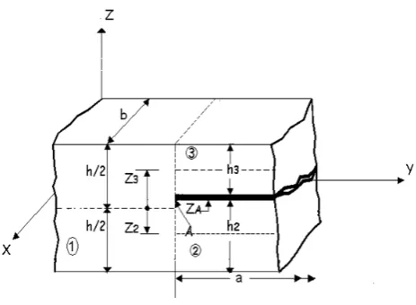
M u l t i p o i n t C o n s t r a i n t s
The cross-sectional view of a typical delamination crack tip is shown in Fig. 4 where the nodes of three plate elements meet together to form a common node. The undelaminated region is model led by plate element 1 of thickness h, and the delaminated region is modeled by plate elements 2 and 3 whose interface contains the delamination (h2 and h3 are the thicknesses of the elements 2 and 3, respectively). The elements 1, 2 and 3 are
freely allowed to deform prior to imposition of the constraints conditions. The nodal displacements of elements 1, 2 and 3 at the crack tip are expressed in Eqn. 34 [Karmakar, A. and Kishimoto, K., 2006].
uj = uoj - (z – zoj) θxj
(34) vj = voj - (z – zo j) θyj
wj = woj (where, j = 2, 3)
Where, , are the mid-plane displacements, is the z coordinate of the mid-plane of element j and , are the rotations about x and y axes, respectively.
Fig. 4 Plate elements at a delamination crack tip
w2 = w3 = w
(35) θx 2 = θx 3 = θx
θy2 = θy3 = θy
The in-plane displacements of all three elements at the crack tip are equal and they are related as uo
2 = uo1 - zo2θx
(36) vo
2 = vo1 - zo2θy
uo
3 = uo1 - zo3θx
vo
3 = vo1 - zo3θy
Where is the mid-plane displacement of element 1. The nodal displacements and rotations of elements 1, 2 and 3 at the delamination crack tip, are the multipoint constraint equations used in the finite element formulation to satisfy the compatibility of displacements and rotations.
Mid-plane strains between elements 2 and 3 are related as
{ } = { } + { } for j=2,3 (37)
Where, { } represents the normal strain vector at mid-plane and {k} is the curvatures vector being identical at the crack tip for elements 1, 2 and 3. This equation can be considered as a special case for element 1 when is equal to zero.
The in-plane stress resultants, {N} and moment resultants, {M} of elements 2 and 3 can be expressed as {N}j = [A] j {εo}1 + (zoj [A] j + [B] j) {k}
(38) {M}j = [B] j {εo}1 + (zoj [B] j + [D] j) {k}
Where [A], [B] and [D] are the extension, bending-extension coupling and bending stiffness coefficients of the composite laminate, respectively [Gim, C.K., 1994]. The elasticity matrix for the tth sub laminate is then
modified and is expressed in the form
[ ] =
+ 0
+ 0
0 0
(39)
Where,
= ⁄ [ ]
⁄ (40)
= ⁄ [ ]
⁄ − (41)
= ⁄⁄ [ ] ( − ) = ⁄⁄ [ ] − 2 ⁄⁄ [ ] + ( ) , = 1,2,6 (42)
= [ ]
⁄ ⁄
, = 4, 5 (43)
Here [ ] is the transformed reduced stiffness as defined in [26] while is the z-coordinate of mid-plane of tth
{N} = {N}1 = {N}2 + {N}3
(44) {M} = {M}1 = {M}2 + {M}3 + z′2 {N}2 + z′3 {N}3
{Q} = {Q}1 = {Q}2 + {Q}3
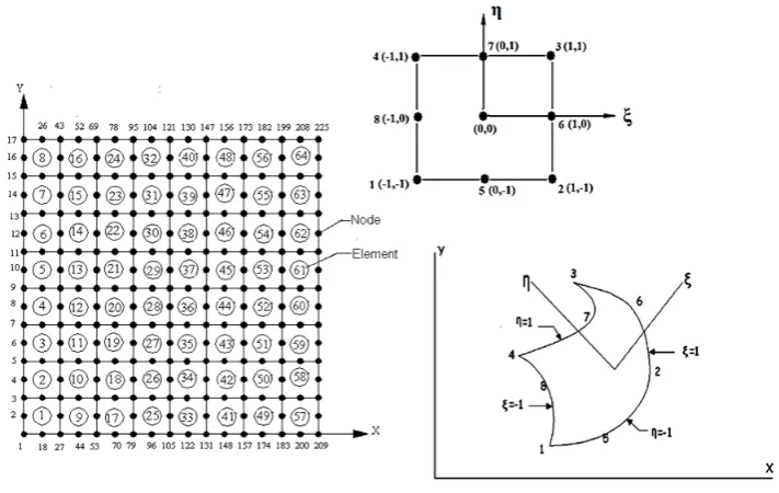
Where {Q} denotes the transverse shear resultants. An eight noded isoparametric quadratic plate bending element with five degrees of freedom at each node (three translations and two rotations) is considered in Fig. 5 wherein the shape functions are given as.
= (1 + )(1 + )( + − 1) Where = 1,2,3,4
=1
2(1 + )(1 − ) Where = 5,7
= (1 + )(1 − ) Where = 6,8 (45) Where, ξ and η are the local natural coordinates of the element and and are the values at a node “i”, i ranges from 1 to 8.
3. Result & Discussion 3.1. Validation:
In order to determine the converged mesh size, convergence studies has been performed. The numerical results are computed using the finite element model for graphite epoxy composite pretwisted shallow conical shells. Obtained results are compared with the results of published literatures as furnished in Table: 1.
Table 1. Convergence study for NDFF = ℎ⁄ , where = ℎ /12(1 − ) of the pretwisted shallow conical shells, considering = 0.3, s/h = 1000, = 30 and = 15
Twist Angle ψ (L/s) Present FEM ( 6 x 6) Present FEM ( 8 x 8) [Liew et al, 1994]
15o 0.2 0.4 0.53241 1.4156 0.55823 1.4587 0.56767 1.4771
0.6 0.32416 0.33872 0.34116
45o 0.2 0.4 0.59632 0.28034 0.61187 0.28189 0.61642 0.28260
0.6 0.20146 0.21007 0.21015
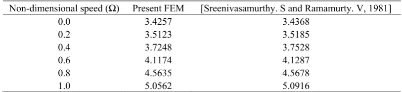
Table 2. Non-dimensional fundamental frequencies = ℎ⁄ of an isotropic rotating cantilever plate, L/b = 1, h/L = 0.12,
= 0.3 and = ℎ /12(1 − )
Non-dimensional speed (Ω) Present FEM [Sreenivasamurthy. S and Ramamurty. V, 1981]
0.0 3.4257 3.4368
0.2 3.5123 3.5185
0.4 3.7248 3.7528
0.6 4.1174 4.1287
0.8 4.5635 4.5678
1.0 5.0562 5.0916
In Table 2, fundamental natural frequencies of an isotropic rotating cantilever plate are shown. The comparative study with the existing literature shows a reasonable agreement with the results which has been published before. This demonstrates precision of the analysis and also the competence of the present computer code, which has been developed. It is observed from the convergence study that, uniform mesh divisions of (6 x 6) and (8 x 8) of the planform of the conical shell provides very close results where the deviation from the published results are marginal. In order to enhance the computational efficiency, negligible deviation of the exact result has been compromised. A mesh size of (6 x 6), having 36 elements and 133 nodes have been considered where each node has five degrees of freedom with thee translations and two rotations.
The present investigation has been carried out to observe the effect of skew and precone angle on the fundamental frequency of shallow pretwisted conical shells with three basic types of laminate configuration viz. Bending Stiff [0 /±30] , Torsion Stiff [± 45/∓ 45] and Quasi Isotropic [0/ ±45 / 90] laminates. At the same time an attempt has been made to see the influence of non-dimensional rotational speeds. The precone angle has been varied from 0o to 90o with an interval of 15o, whereas the skew angle has been varied for 0o, 45o
and 90o. The effect of twist angle has been observed for untwisted shell and twisted shells having a twist angle
30o. The fundamental frequency has been calculated for undelaminated and delaminated shells. In case of
delaminated shells, delamination has been considered at the mid plane of the laminates with relative crack length (a/l) of 33%.
In order to see the effect of skew, precone angle and angle of twist on the natural frequencies with respect to rotational speeds, parametric studies have been conducted. Non dimensional frequencies of conical shells having L/b0 = 0.7 and thickness ration (s/h) of 1000 are found corresponding to non-dimensional rotational speed Ω = (Ω / ) varying from 0 to 1. The and has been considered as 45o and 20o respectively. The relative
distance has been considered as d/L = 0.5 with twist angle = 30 along with the untwisted one = 0 . For investigating the consequences of delamination, single delamination has been considered at the mid plane of the laminates where the total no of layers is equal to 8 ( n= 8). The skew angle and precone angle has been varied from 0 90 with an interval of 45 15 respectively. For the finite element formulation an eight noded isoparametric shell element with five degrees of freedom at each node has been considered. The material properties of graphite epoxy composite are assumed as [Qatu and Lieissa, 1991], E1 = 138.0 GPa, E2 = 8.96
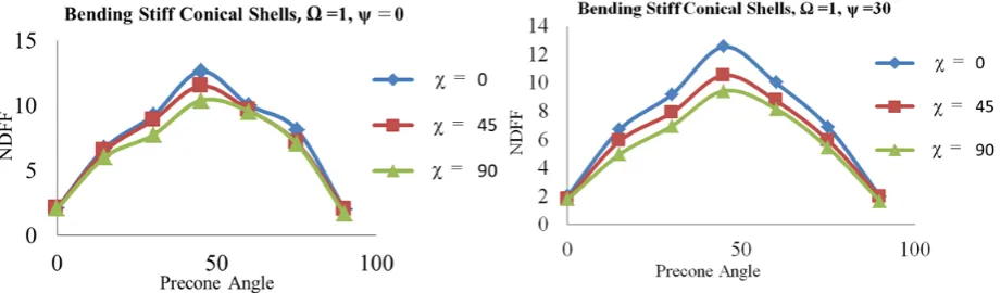
Non-dimensional fundamental frequencies (NDFF) for undelaminated bending stiff composite conical shells
[0 /±30] for skew angle 0 , 45 and 90 has been plotted in Fig 6 for untwisted and twisted shells respectively. For the case of undelaminated quasi isotropic laminate [0/ ±45 / 90] and torsion stiff laminate
[± 45/∓ 45] , variation of NDFF with respect to precone angles at various skew angle are plotted considering twist angle 0 30 in Fig. 7 - 8.
Fig 6: Fundamental Frequency vs. Precone Angle for undelaminated Bending Stiff Conical Shells at Ω = 1 , twist angle ψ = 0 (left) & ψ = 30 (right)
Fig 7: Fundamental Frequency vs. Precone Angle for undelaminated Quasi Isotropic Conical Shells at Ω = 1 , twist angle ψ = 0 (left) & ψ = 30 (right)
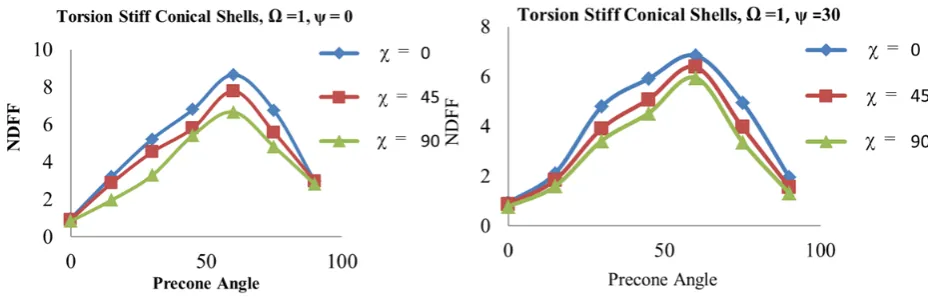
Fig 8: Fundamental Frequency vs. Precone Angle for undelaminated Torsion Stiff Conical Shells at Ω = 1 , twist angle ψ = 0 (left) & ψ = 30 (right)
Fig 9: Fundamental Frequency vs. Precone Angle for Bending Stiff Conical Shells with mid plane delamination at Ω = 1 , twist angle ψ = 0 (left) & ψ = 30 (right)
Fig 10: Fundamental Frequency vs. Precone Angle for Quasi Isotropic Conical Shells with mid plane delamination at Ω = 1, twist angle ψ = 0 (left) & ψ = 30 (right)
Fig 11: Fundamental Frequency vs. Precone Angle for Torsion Stiff Conical Shells with mid plane delamination at Ω = 1 , twist angle ψ = 0 (left) & ψ = 30 (right)
The fundamental frequency for Bending stiff composite laminates is maximum for skew angle = 0o, and
gradually decreases for higher value of skew angle (45o and 90o). The effect of twist angle is not dominant on
fundamental frequencies can be observed irrespective of laminate configurations as shown in Fig. 9 – 11. This attributes to fact of decrease in the geometric stiffness of the laminate due to presence of delamination. The fundamental frequency gets significantly reduced at higher values of skew angle for twisted shells, whereas for untwisted shells the fundamental frequency decays in a sluggish manner in the same situation. Like bending and quasi isotropic shells, in case of torsion stiff shells also, twist angle has dominant effect on the value of fundamental frequency at higher value of skew angle. Table 3 – 4 shows the non-dimensional fundamental frequencies at Ω = 0.5 for twisted and untwisted conical shells, whereas Table 5 – 6 shows the same in presence of mid plane delamination.
Table: 3 Effect of Skew and Precone Angles on undelaminated bending stiff, torsion stiff and quasi isotropic pretwisted conical shells at
Ω = 0.5 and ψ = 0o
Precone Angle
(β)
Bending Stiff Conical Shells Torsion Stiff Conical Shells Quasi Isotropic Conical Shells
Skew Angle (α ) Skew Angle (α ) Skew Angle (α )
0o 45o 90o 0o 45o 90o 0o 45o 90o
0o 1.3719 1.2769 1.1277 1.2754 1.1657 1.0756 1.3240 1.2457 1.1935
15o 4.3214 3.8304 3.3304 3.1817 2.6572 2.1572 3.9813 3.5728 3.1728
30o 6.9099 6.1258 6.0652 5.1318 4.4561 4.1555 5.3776 4.8466 4.2744
45o 8.8953 8.2730 7.9765 6.9512 5.8506 4.7305 7.2880 6.5047 5.8799
60o 5.2025 4.7246 4.2359 4.0562 3.4477 3.2092 4.3893 3.5917 3.2233
75o 3.8082 3.4311 3.2901 2.7847 2.1077 1.8739 3.4545 2.7968 2.3707
90o 1.4812 1.3252 1.1968 1.8154 1.5905 1.4486 1.2401 1.1428 1.0589
Table: 4 Effect of Skew and Precone Angles on undelaminated bending stiff, torsion stiff and quasi isotropic pretwisted conical shells at Ω
= 0.5 and ψ = 30o
Precone Angle (β)
Bending Stiff Conical Shells Torsion Stiff Conical Shells Quasi Isotropic Conical Shells
Skew Angle (α ) Skew Angle (α ) Skew Angle (α )
0o 45o 90o 0o 45o 90o 0o 45o 90o
0o 1.1603 1.0748 1.0641 1.1681 1.0571 0.9850 1.1250 1.0571 0.9852
15o 3.2591 2.8421 2.1421 2.4246 1.7084 1.0844 2.6361 1.9569 1.6569
30o 5.2929 4.9517 3.9087 4.2796 3.3946 2.6758 4.6839 3.8267 3.1252
45o 6.9674 5.5054 4.7560 5.9925 4.8165 4.0123 6.4112 5.7754 4.8070
60o 4.2851 3.5497 2.9395 3.1731 2.6011 2.0309 3.4323 2.9186 2.4226
75o 2.3792 1.8592 1.3732 1.9402 1.6949 1.3161 2.5720 2.1043 1.7604
90o 1.0659 0.9626 0.9333 1.1713 1.0835 0.9150 1.1443 1.0773 0.9712
Table: 5 Effect of Skew and Precone Angles on bending stiff, torsion stiff and quasi isotropic pretwisted conical shells with mid plane delamination at Ω = 0.5 and ψ = 0o
Precone Angle (β)
Bending Stiff Conical Shells Torsion Stiff Conical Shells Quasi Isotropic Conical Shells
Skew Angle (α ) Skew Angle (α ) Skew Angle (α )
0o 45o 90o 0o 45o 90o 0o 45o 90o
0o 1.3127 1.2583 1.1597 1.1973 1.1553 1.0432 1.3156 1.2588 1.1937
15o 4.0081 3.7359 3.3590 2.7637 2.3035 2.1035 3.2529 2.8555 2.5554
30o 6.1844 5.9629 5.3096 4.9675 4.3773 3.9612 5.2675 4.8187 4.6172
45o 8.1663 7.8303 6.9374 6.6515 5.7028 4.9795 6.8650 5.9081 5.6004
60o 4.8624 3.9525 3.4025 3.8885 3.6784 2.9412 4.1466 3.8134 3.5357
75o 3.4051 2.8778 2.5865 2.2903 2.1449 1.7625 2.8598 2.4882 2.3666
Table: 6 Effect of Skew and Precone Angles on bending stiff, torsion stiff and quasi isotropic pretwisted conical shells with mid plane delamination at Ω = 0.5 and ψ = 30o
Precone Angle
(β)
Bending Stiff Conical Shells Torsion Stiff Conical Shells Quasi Isotropic Conical Shells
Skew Angle (α ) Skew Angle (α ) Skew Angle (α )
0o 45o 90o 0o 45o 90o 0o 45o 90o
0o 1.0603 0.9675 0.8964 0.9681 0.8587 0.6825 1.0387 1.0262 1.0193
15o 3.1606 2.6222 2.1322 2.2431 1.6434 0.9842 2.4158 1.9602 1.4602
30o 4.8653 3.8820 3.2087 3.8756 2.8395 2.3948 4.1640 3.5160 2.9180
45o 6.2343 5.3424 4.7956 4.7963 4.1482 3.6754 5.7587 4.5303 3.7253
60o 4.0751 3.6796 2.7490 2.9813 2.4539 1.9525 2.9802 2.2727 1.7185
75o 1.9879 1.8592 1.3542 1.7543 1.5297 1.2671 2.4655 1.8568 1.4312
90o 1.0453 0.9236 0.8533 1.0658 0.9835 0.9743 1.0912 0.9420 0.9277
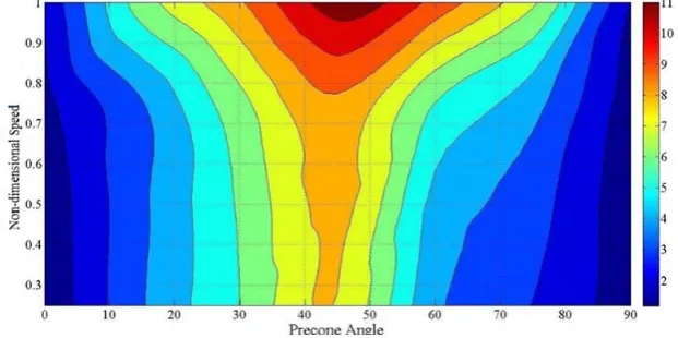
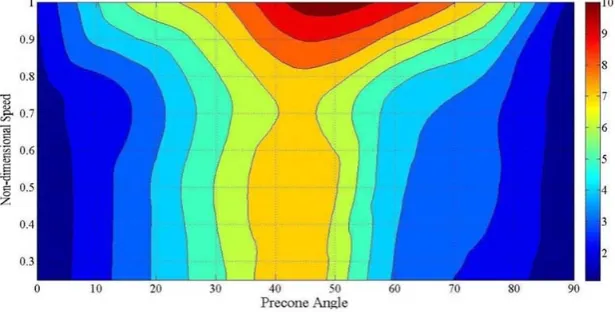
In order to investigate the effects of rotational speed, twist angle, skew angle and precone angle on the non-dimensional fundamental frequency various laminate configurations, contour plots have been plotted with MATLAB for bending stiff pretwisted conical shells as shown in Fig 12 - 16. The x and y axis of the plot denotes the variation of precone angle and non-dimensional speed respectively. The legend color shows the range of the value of the non-dimensional fundamental frequency.
Fig 12. Effect of non-dimensional speed on the fundamental frequencies of undelaminated bending stiff conical shells with skew angle (χ)
= 0o, ψ = 0o
Fig 13. Effect of non-dimensional speed on the fundamental frequencies of undelaminated bending stiff conical shells with skew angle (χ)
Fig 14. Effect of non-dimensional speed on the fundamental frequencies of undelaminated bending stiff conical shells with skew angle (χ)
= 90o, ψ = 0o
Fig 15. Effect of non-dimensional speed on the fundamental frequencies of bending stiff conical shells with mid plane delamination, skew
angle (χ) = 45o, ψ = 30o
Fig 16. Effect of non-dimensional speed on the fundamental frequencies of undelaminated bending stiff conical shells with skew angle (χ)
= 45o, ψ = 30o
An interesting trend may be observed for the case of maximum non dimensional frequency irrespective of laminate configurations. It has been seen that maximum non dimensional frequency is obtained at Precone angle ranging from 40o – 45o. Fig. 12 -13 shows that, high value of non-dimensional fundamental frequency may be
precone angle (β = 90), non-dimensional fundamental frequency value gradually gets reduced and almost becomes equal to the frequency value at β = 0.
CONCLUSION:
Eight noded isoparametric shell element has been developed based on which finite element method has been formulated to investigate the free vibration characteristics of rotating composite pretwisted conical shells having three basic laminate formations. Structural parameters like angle of twist, skew angle and precone angle has been varied in order to see the influence of these parameters on the free vibration characteristics. A common trend has been observed while varying the precone angles, regardless of the other parameters. The value of non-dimensional frequency rises to maximum at a precone angle range of 400 – 450 and after that it gradually
reduces to minimum value at precone angle 900. With the increase of skew angle non-dimensional frequency
gradually decreases. This trend is observed in all the three basic laminate configurations viz. bending stiff [0 / ± 30] , Torsion Stiff [±45/ ∓45] and quasi-isotropic laminates[0/±45/90] . With the increase of twist angle (ψ) fundamental frequency gradually decreases. At skew angle 450 angle of twist has considerable
influence on the fundamental frequency compared to the skew angle value = 00. Bending stiff pretwisted shells
exhibits the maximum fundamental frequency followed by quasi isotropic and torsion stiff laminates. The presence of delamination influences the geometric stiffness matrix of the laminate, as a result fundamental frequency gets reduces due to it. The effect of non-dimensional speed on the non-dimensional frequencies with the influence of skew and precone angle also has been investigated. In general, maximum fundamental frequency occurs at a specific precone angle range (400 – 450) irrespective of the influence of any other
parameters. For bending stiff laminates, non-dimensional speed has pronounced effect on maximum fundamental frequency at higher value of skew angle (χ). The results furnished here are first known natural frequencies for the shallow pretwisted conical shells under the influence of varying structural parameters and it may serve as a ready reference for future studies.
Acknowledgements:
Authors sincerely acknowledge the Department of Mechanical Engineering of Jadavpur University , Specially the Applied Mechanics Section for extending all sorts of help from time to time.
References
[1] Aydogdu, M; Timarci, T: Vibration analysis of cross-ply laminated square plates with general boundary conditions, Compos. Sci. Technol. 63 (7) (2003) 1061–1070.
[2] Berthelot, J.M.; Le Corre, J.F: Statistical analysis of the progression of transverse cracking and delamination in cross-ply laminates, Compos. Sci. Technol. 60 (14) (2000) 2659–2669
[3] Bhumbla, R.; J.B. Kosmatka and J.N. Reddy. (1990): “Free Vibration behavior of spinning shear deformable plates composed of Composite Materials,” AIAA J. 28: 1962 – 1970
[4] Chamis, C.C: “Vibration Characteristics of Composite Fan Blades and Comparison with measured data”, J. Aircraft, 14: 644 – 647, 1977.
[5] Gim, C.K. "Plate finite element modeling of laminated plates". Comput. Struct. 1994; 52(1):157 – 168.
[6] J.L. Rebiere, D. Gamby, A criterion for modeling initiation and propagation of matrix cracking and delamination in cross-ply laminates, Compos. Sci. Technol. 64 (13–14) (2004) 2239–2250
[7] Karmakar, A., Sinha, P.K., (1997).”Finite Element Free Vibration Analysis of rotating Laminated Composite Pretwisted Cantilever Plates”, Vol. 16, No. 16: 1461 – 1491.
[8] Karmakar, A. and Kishimoto, K. "Free Vibration Analysis of Delaminated Composite Pretwisted Rotating Shells – A Finite Element Approach". JSME International Journal, Series A. 2006; 49(4):492-502.
[9] Krawczuk, M; Ostachowicz. W: A. Zak, Dynamics of cracked composite material structures, Comput. Mech. 20 (1997) 79–83. [10] Lee, J.J; C.H. Yeom, I. Lee: Vibration analysis of twisted cantilever conical composite shells, J. Sound Vib. 255 (5) (2002) 965–982 [11] Liang, H.L. Sen; T. Chen, Chen, M.Y. Wang: The natural vibration of a symmetric cross-ply laminated composite conical-plate shell,
Compos. Struct. 80 (2006) 265–278.
[12] Liew, K.M; Lim, C.M; Ong, L.S: Vibration of pretwisted cantilever shallow conical shells, Int. J. Solids Struct. 31 (1994) 2463– 2474.
[13] McGee, O.G and H.R. Chu. “Three dimensional vibrational analysis of rotating laminated composite blades”, J. Engg. Gas Turbines and Power, Trans. ASME (1994), 116: 663 – 671
[14] Nabi, S. M. and Ganesan.N: “ Vibration and Damping Analysis of Pre twisted Composite Blades.” , Computers and Structures (1993), 47 (2): 275 – 280
[15] Narita, Y; Ohta, Y; Saito, M: Finite element study for natural frequencies of cross-ply laminated cylindrical shells, Compos. Struct. 26 (1–2) (1993) 55–62.
[16] Parhi, P.K; Bhattacharyya,S.K; Sinha,P..K: Failure analysis of multiple delaminated due to bending and impact, Bull. Mater. Sci. 24 (2) (2001) 143–149.
[17] Qatu, M.S; A.W. Leissa, Vibration studies for laminated composite twisted cantilever plates, Int. J. Mech. Sci. 33 (1991) 927–940 [18] Sallam, S. Simitses, G.J: Delamination buckling and growth of flat, cross-ply laminates, Compos. Struct. 4 (4) (1985) 361–381. [19] Sreenivasamurthy, S., Ramamurti, V: ”Coriolis effect on the vibration of flat rotating low aspect ratio cantilever plates,” Journal of
Strain Analysis, Vol. 16 No. 2: (1981) 97 – 106
[21] Todoroki, A; Tanaka, Y. Shimamura,Y: Delamination monitoring of graphite/epoxy laminated composite plate of electric resistance change method,Compos. Sci. Technol. 62 (9) (2002) 1151–1160.
[22] Toyama, N; Noda, J; Okabe, T: Quantitative damage detection in cross-ply laminates using Lamb wave method, Compos. Sci. Technol. 63 (10) (2003) 1473–1479.
[23] V. Tripathi, B.N. Singh, K.K. Shukla, Free vibration of laminated composite conical shells with random material properties, Compos. Struct. 81 (2007) 96–104.