138 |
P a g e
DESIGN AND IMPLEMENTATION OF MICROSTRIP PATCH
ANTENNA USING METAMATERIALS FOR BIOMEDICAL
APPLICATIONS
Priyanka.A, Aachal.M, Niharika.K,Manjulatha, Siddanagouda.F.B
Dept. of Electronics& Communication Sphoorthy Engineering College Hyderabad (India)
ABSTRACT
In this workcircularmicrostrip patch antenna using rectangular spilt ringmetamaterial unit cell is designed,
simulated and analyzed. The rectangular split ring metamaterial unit cell and conventional circular microstrip patch antenna are designed using FR-4 substrate with dielectric constant 4.4. The overall dimensions of conventional circular microstrip patch antenna and rectangular split ring metamaterial unit cell are 62X36X1.6mm3, 20X20X1.6mm3respectively. Then designed metamaterial unit cell is loaded on the ground plane of conventional circular microstrip patch antenna is resonated from 2.34GHz to 3.4GHz with overall bandwidth of 200MHz. Simulated results include bandwidth gain VSWR and radiation pattern. The proposed circular patch Antenna is compared with the conventional circular patch antenna, which shows the significant miniaturization as compared to conventional circular patch antenna hence the proposed antenna shows good results and it is well suited for biomedical application wireless devices.
Keywords:CircularMicrostrip patch antenna,Rectangular split-ring,biomedicaldevice, Bandwidth
I.
INTRODUCTION
In Recent years, need for the deployment of wireless telemetry systems in medicine has significantly increased
due to necessity for early diagnosis of diseases and continuous monitoring of physiological
parameters.Microwave antennas and sensors are key components of these telemetry systems since they provide
the communication between the patient and base station.Nowadays, the major microwave applications in the
medical field are in data telemetry, medical diagnosis and treatment (see in Figure 1.1).
139 |
P a g e
Data telemetry: Data telemetry refers to wireless data transmission using microwaves between implantedmedical devices (IMDs) and external devices. Due to the rising demand of health care products, IMDs have
gained much interest for healthcare providers. Examples are: bladder stimulators and pacemakers, glucose
monitoring for diabetics, which are widely usedwith the use of traditional IMDs, the wires used to connect to the
devices for the diagnosis signals increase the pain and risk of infection in the patients. With the help of wireless
link, the continuous monitoring of the state of implanted devices can also be achieved.
Medical diagnosis using microwaves: The applications for medical diagnosis are used in the detection of
breast cancer, stroke, water accumulation in human body, etc. Among these, one of the most important
applications of medical diagnosis is the detection of breast cancer, which is the most dangerous form of cancer
among women. Approximately one million women around the world suffer from breast cancer. Therefore,
technologies with high accuracy and sensitivity to detect the presence of tumors are required. An almost
pain-free examination with a short examination time and a portable apparatus is especially desirable for the detection
of early-stage breast cancer.
Medical treatment using microwaves:Medical treatment using microwaves is based on using the heat
generated by microwave radiation to increase the local temperature to destroy the abnormal tissues (e.g.
malignant tissues). This technique is more sensitive and effective compared to ionizing radiation (i.e. X-ray) and
chemical toxins (i.e. Chemotherapy).
140 |
P a g e
Telemedicine refers to the use of telecommunication for the transmission of health information to deliver
clinical healthcare from a distance .A vision of the future telemedicine for a healthcare system for nursing home
residents using microwaves is illustrated in Figure 2. The medical diagnosis system serves to monitor health
problems such as stroke for prompt diagnosis and treatment. On the other hand, the data transmission between
IMDs and external devices are performed simultaneously. In this way, the combination between medical
diagnosis and data telemetry using microwaves contributes very positively to the existing healthcare services. In
the data telemetry of this healthcare system, the physiological data (temperature ,blood pressure, glucose
concentration) or vital signs (such as respiration ,heart beating, etc.) are monitored by sensors integrated on the
implants .The implants are wirelessly powered by an antenna at a certain frequency(usually very low frequency
in the MHz range). The wireless data transmission between implants and external medical devices is performed
at a high frequency (in the GHz range) at the medical center, the received data is forwarded to the healthcare
practitioner to evaluate the patient’s status. In the case where abnormalities are detected, the doctor is
immediately informed so that necessary actions can be initiated in time. The vision shown in Figure 2 is the
development of suitable antennas for IMDs and medical diagnosis using radar imaging. For such applications,
the antenna for radiating and receiving the signals is the governing factor of the SNR of the overall system.
Metamaterials are artificial materials which have the electromagnetic propertiesthat may not be found in nature.
The unusual properties of a metamaterial have led to thedevelopment of metamaterial antennas, sensors and
metamaterial lenses for miniature wireless systems which are more efficient than their conventional
counterparts. Metamaterialsexhibita very sensitive response to the strain, dielectric media, chemical and
biological sensing applications. The design concept of metamaterial circular microstrip patch antennas in ISM
band is presented by using FR4 substrate with 4.4 dielectric constant and result shows well suited for biomedical
applications.
II.
RECTANGULAR SPLIT RING METAMATERIAL STRUCTURE (RSRM):
Figure3: RSRM Unit Cell
An attractive properties of metamaterial is that plane wave propagating in the media would there phase velocity
antiparallel with group velocity so that media would support backward waves. In this paper we proposed a
periodic rectangularsplit ring resonator structure (SRSM) a unit cell is depicted in figure 3.This metamaterial
141 |
P a g e
constant of 4.4. The dimension of the unit cell is shown in table 1. The resonance frequency of this rectangular
split ring unit cell structure depends on the gap dimension (g). By increasing the gap, the capacitance in LC
circuit model of the unit cell decreases. The decrement of the capacitance, results the increment of the resonance
frequency of the structure.
Parameters Dimensions(mm)
Length of the substrate 30
Width of the substrate 30
Length of rectangle split ring , L 20
Width of rectangle split ring, W 20
Thickness, d 0.03
Gap, G 0.2
Distance between the split ring 0.2
Table1: Dimensions of RSRM
In all of the previous work, slot loaded miniaturized patch antennas were used in biomedical applications. Such
patch antennas were never extended and analyzed by metamaterialstructure.Hence here we designed rectangular
split ring metamaterial structure and it loaded on ground plane of the conventional circular microstrip antenna so
that we achieved 75% of size reduction and good amount of bandwidth and gain for biomedical and wireless
applications.
III.
ANTENNA DESIGN
A.
Conventional Microstrip Patch Antenna
In this paper we proposed a circular microstrippatch antenna having radius 16.3mm using Fr-4 substrate with
4.4 dielectric constant and having thickness of the substrate 1.6mm .The overall dimension of the circular
microstrip patch antenna are shown in table2.and conventional circular microstrip patch antenna as shown in
figure 4 .
142 |
P a g e
Parameter Dimensions (mm)
Radius, r 16.3
Length of the substrate, L 62
Width of the substrate, W 36
Quarter wave length of thefeed line, Lq 10
Quarter wave Width of the feed line, Wq 0.7
Length of thefeed line, Lf 17.11
Width of the feedline, Wf 3.059
Thickness of the substrate 1.6
Table2: Dimensions of the Conventional Microstrip Patch Antenna
B.
MetamaterialMicrostrip Patch Antenna
In this work designed rectangular split ring metamaterial structure loaded on the ground plane of the
conventional circular microstrip patch antenna so that we etched the RSRM structure on the ground plane of the
conventional microstrip patch antenna, so that RSRM structure is actively coupled with conventional circular
microstrip patch antenna hence it shows that the antenna miniaturized to 75% of size reduction as compared to
conventional circular microstrip patch antenna, and it supported 200MHz bandwidth as well as 2.4dB gain more
than conventional microstip patch antenna bandwidth and gain was 100MHz, 2dB respectively. The designed
metamaterial circular microstrip patch antenna is shown in figure 5.after that by varying the width and gap of
the metamaterial structure parametric studies was done for the better improvement of bandwidth and gain and
efficiency for biomedical applications. so that here we simulated and compared conventional microstrip antenna
result with proposed met material micro strip patch antenna.
Figure5: Metamaterial Circular Microstrip Patch Antenna top and bottom view
IV.
RESULTS:
I
n this section we are presenting the design and simulated results for the conventional microstrip patch antenna143 |
P a g e
antenna results like scattering parameter, bandwidth, gain, VSWR, radiation pattern after that we presented our
proposed metamaterialmicrostrip patch antenna for the same parameter like scattering parameter, bandwidth,
gain, VSWR, radiation pattern, then we summarized the result in table 3
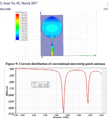
Figure6: Reflection coefficient of conventional microstrip patch antenna
Figure 6 shows the reflection coefficient conventional microstrip patch antenna is that -18.31dB at 2.56GHz and
it supported bandwidth 100MHz.
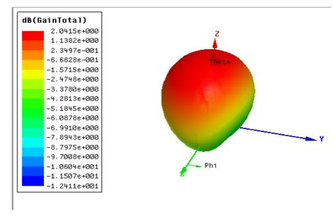
Figure 6: 3D gain pattern of conventional microstrip patch antenna
Figure 6 show that conventional microstrip patch antenna supported gain is about 2dB, and figure 7 show the
144 |
P a g e
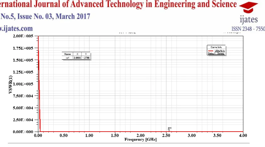
Figure7: VSWR of conventional microstrip patch antenna
The radiation pattern and current distribution pattern of conventional circular microstrip patch antenna are
shown in figure 8 and figure9 respectively. And figure 10 shows the proposed metamaterial circular microstrip
patch antenna reflection coefficient bandwidth here the proposed antenna resonate a dual band frequencies are
2.32GHz and 3.4GHz with supported 200MHz bandwidth, so that as compare with conventional microstrip
patch antenna we achieved 75% of size reduction as well as increased in bandwidth and it resonate at dual
frequencies. Figure 11 show the gain parameter of the proposed antenna is 2.4dB hence proposed antenna gain
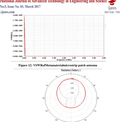
improvement far better than conventional microstrip patch antenna. Figure 12 and figure 13 shows the VSWR
and radiation pattern of the proposed metamaterial circular microstrip patch antenna.
145 |
P a g e
Figure 9: Current distribution of conventional microstrip patch antenna
Figure 10: Reflection Coefficient ofMetamaterialmicrostrip patch antenna
146 |
P a g e
Figure 12: VSWRofMetamaterialmicrostrip patch antenna
Figure 13: Radiation patternofmetamaterialmicrostrip patch antenna
Parameters Conventional Antenna Proposed Antenna
Resonating Frequency 2.56GHz 2.32GHz, 3.4GHz
Reflection Coefficients -18.31dB -17.20dB, -13dB
Bandwidth 100MHz 200MHz
Gain 2.0dB 2.4dB
VSWR 1,21 1.21
Table 3: Compression of conventional and proposed microstrip patch antenna
V.
CONCLUSION
A new antenna has been designed and simulated using rmetamaterial at the frequency range of 2.3GHz-3.4GHz.
Bandwidth of 200MHz.Theproposed Circular microstrippatchantenna with metamaterial gives a multiband
operation compared to conventional microstrip patch antenna.Byanalyzing the simulation result, it is found that
the bandwidth and gain is also increased by using metamaterial structure. Further the size of antenna is also
147 |
P a g e
ACKNOWLEDGEMENT
We thank Department of Electronics & Communication Sphoorthy Engineering College Hyderabad for
providing an research environment, laboratory facility to design metamaterial antenna for biomedical and
wireless applications.
Biography of the authors
Priyanka.ACurrently she is pursuing her B.Tech in the department of Electronics&
Communication, Sphoorthy Engineering College Hyderabad.Her research area interest
includesmetamaterial antenna, and IOT Application system design.
Aachal.M Currently she is pursuing her B.Tech in the department of Electronics&
Communication, Sphoorthy Engineering College Hyderabad.Her research area interest
includesmetamaterialmicrostrip antenna, and Signal Processing.
Niharika.K Currently she is pursuing her B.Tech in the department of Electronics&
Communication, Sphoorthy Engineering College Hyderabad.Her research area interest
includesmetamaterialmicrostrip antenna, and Microwave Engineering.
Manjulatha.Treceived her Btech from Bhojreddy Engineering college in 2003 and ME
from Osmania university with Microwave and RADAR specialization in 2006.Currently
she is pursuing her PhD in the field of Microwave antennas from KLUniversity.Her
research area interest include microwave components and antennas. Currently she is
working as an Assistant professor in Sphoorthy engineering college in the department of
ECE
Siddanagouda.F.B received his BE and M.Tech from PES College of Engineering
Mandya and IIT Kharagpur in the year 2009 and 2012 respectively. Currently he is
pursuing his Ph.D. in the field of Microwave Antennas from the department of Applied
Electronics, Gulbarga University Gulbarga. His research area interest
includeMetamaterial antenna, Dielectric resonator antenna and wireless communication
system design.
REFERENCES
[1]. Smith, R. A., D. Saslow, K. A. Sawyer, W. Burke, M. E. Costanza, W. P. Evans, R. S. Foster, E.
Hendrick, H. J. Eyre, and S. Sener, \American cancer society guidelines for breast cancer screening:
148 |
P a g e
[2]. P.Katehi, N. Alexopoulos, and I. Hsia, "A bandwidth enhancement method for microstrip antennas,
vol.35 no.1, Jan 1987.
[3]. A. Wood, et al., “ALARM-NET: Wireless Sensor Networks for Assisted-Living and Residential
Monitoring,” Technical Report CS-2006-13, University of Virginia, 2006.
[4]. A.Milenkovic, et al., “Wireless Sensor Networks for Personal Health Monitoring: Issues and an
Implementation,” Computer Communications, Vol. 29, No. 13-14, 2006, pp. 2521-2533.
[5]. G. J. Pottie and W. J. Kai, “Wireless Integrated Network Sensors,” Communications of the ACM, Vol.
43, No. 5, 2000, pp. 51-58
[6]. V. Jones, et al., “Biosignal and Context Monitoring: Distributed Multimedia Applications of Body Area
Networks in Healthcare,” 2008 IEEE 10th Workshop on Multimedia Signal Processing, Cairns, 8-10
October 2008, pp. 820- 825.
[7]. A. Karlsson Physical Limitations of Antennas in a Lossy Medium. IEEE Transactions on Antennas and
Propagation,52(8):2027–2033, August 2004.
[8]. D. S. Cap. Efficacy of Adjuvant Hyperthermia in the Treatment of Superficial Recurrent Breast Cancer:
Confirmation and Future Directions. Int. J. Rad. Oncol. Biol. Phys., 35:117–1121, 1996.
[9]. F. Huang, C. Lee, C. Chang, L. Chen, T. Yo, and C. Luo.Rectenna Application of Miniaturized
Implantable Antenna Design for Triple-Band Biotelemetry Communication. IEEETransactions on
Antennas and Propagation, 59(7):2646–2653, July 2011
[10]. S. Gabriel, R. W. Lau, and C. Gabriel. The Dielectric Properties of Biological Tissues: II. Measurements
in the Frequency Range 10 Hz to 20 GHz. Phys.Med. Biol., 41(11):2251–2269,November 1996.
[11]. M. Klemm, I. J. Craddock, J. A. Leendertz, A. Preeceand R. Benjamin. Radar-Based Breast Cancer