Installation
Operation
and
Maintenance
Instructions
Built In
All Freezer
M18AF
M24AF
M30AF
M36AF
is committed to building a quality product
NOTE
!
CAUTION
Important Safety Instructions
Warnings and safety instructions appearing in this guide are not meant to cover all possible conditions and situa-tions that may occur. Common sense, caution, and care must be exercised when installing, maintaining, or operat-ing this appliance.
Recognize Safety Symbols,
Words, and Labels.
!
WARNING
WARNING-
Hazards or unsafe practices with high probability of personal injury or property / prod-uct damage.CAUTION-
Hazards or unsafe practices which could result in personal injury or property or product damage.NOTE-
Important information to help assure a problem free installation and operation.CONTENTS
Unpacking the freezer ...3
Tools required ...3
Warranty registration ...4
Dimensions for M(XX)AF with Solid Door ...5
Dimensions for M(XX)AF with Solid Overlay Door ...6
Pre installation considerations ...7
Rough in opening ...7
Select location ...7
Electrical requirements ...8
Plumbing requirements ...8
Corner installation ...9
Installing the cabinet ...10
Anti tip bracket considerations ...10
Leveling the unit ...11
Installing the power module ...12
Placing power module on top of cabinet ...12
Power module electrical connections ...12
Installing the ice maker water valve ...13
Installing the grille ...14
Custom Grille and Door Overlay Panels ...17
Mounting Grille Overlay Panel ...17
Overlay Door Panel Instructions ...18
Hinge and gasket adjustments ...20
Installing side panels ...21
Installing the kickplate ...21
Installation checks ...22
Common installation errors ...22
Use and care guide ...23
Using your freezer ...23
Temperatures ...24
Defrosting ...24
Cleaning ...24
Condenser cleaning procedure ...24
Energy saving tips ...25
Product sounds ...25
Troubleshooting guide ...26
Obtaining service ...26
!
CAUTION
!
CAUTION
!
WARNING
EXCESSIVE WEIGHT HAZARD
Use two or more people to move product.
Failure to do so can result in back or other injury.
Remove Interior Packaging
Your freezer has been packed for shipment with all parts that could be damaged by movement securely fastened. Remove internal packing materials and any tape holding in-ternal components in place. The owners manual is shipped inside the product in a plastic bag along with the warranty registration card, and other accessory items.
Important
Keep your carton and packaging until your freezer has been thoroughly inspected and found to be in good condi-tion. If there is damage, the packaging will be needed as proof of damage in transit. Afterwards please dispose of all items responsibly in particular the plastic bags which can be a suffocation hazard.
Note to Customer
This merchandise was carefully packed and thoroughly inspected before leaving our plant. Responsibility for its safe delivery was assumed by the retailer upon acceptance of the shipment. Claims for loss or damage sustained in transit must be made to the retailer.
DO NOT RETURN DAMAGED MERCHANDISE TO THE MANUFACTURER - FILE THE CLAIM WITH THE RE-TAILER.
If the power module was shipped or has been laying on its side for any period of time allow the power module to sit upright for a period of at least 24 hours before plugging
Help Prevent Tragedies
Child entrapment and suffocation are not problems of the past. Junked or abandoned freezers are still dangerous - even if they sit out for "just a few days".
If you are getting rid of your old freezer, please follow the instructions below to help prevent accidents.
Before you throw away your old freezer: • Take off the doors or remove the drawers.
• Leave the shelves in place so children may not easily climb inside.
UNPACKING YOUR FREEZER
Tools to have available for installation:
• Phillips screwdriver • Flat blade screwdriver
• Hex head nut drivers size 1⁄4" and 5⁄16"
• Level
• Drill and drill bit (#6 - .204)
• Open end wrenchs size 1⁄4", 7⁄16" and 1⁄2"
• Slip joint pliers • Adjustable wrench • Tape measure
• Hex socket and ratchet size 7⁄16"
Power module serial plate is behind the grille on the front of the power
module-Cabinet serial plate is on the inside top liner toward the right
side-It is important you send in your warranty registration card immediately after taking delivery of your freezer.
The following information will be required when registering your unit.
Service Number Serial Number Date of Purchase
Dealer’s name and address
The service number and serial number can be found on the
Warranty Registration
Figure 2 Power module serial plate Figure 3 Cabinet Figure 1 Serial plate locationsWARRANTY REGISTRATION
PRODUCT DIMENSIONS FOR M(XX)AF WITH SOLID DOOR
"A" "B" 1⁄2" (12.7mm) 1⁄2" (12.7mm) 241⁄2" (62.2cm) 11" (27.9cm) 73" to 735⁄8" (185.4cm to 187cm) 84" to 845⁄8" (213.4cm to 214.9cm) 273⁄16" (69.1cm) 29⁄16" (6.5cm) "C" MODEL "A" "B" "C" M18AF-WS 18" (45.7cm) 17" (43.2cm) 4111⁄16" (105.9cm) M18AF-SS 18" (45.7cm) 17" (43.2cm) 4111⁄16" (105.9cm) M24AF-WS 24" (61cm) 23" (58.4cm) 4711⁄16" (121.1cm) M24AF-SS 24" (61cm) 23" (58.4cm) 4711⁄16" (121.1cm M30AF-WS 30" (76.2cm) 29" (73.7cm) 5311⁄16" (136.4cm) M30AF-SS 30" (76.2cm) 29" (73.7cm) 5311⁄16" (136.4cm) M36AF-WS 36" (91.4cm) 35" (88.9cm) 593⁄4" (151.8cm) M36AF-SS 36" (91.4cm) 35" (88.9cm) 593⁄4" (151.8cm)Electrical Requirements:
A grounded 115 volt, 60 cycle, single phase, 15 amp dedicated circuit is required. Follow all local building codes when installing electrical and unit.
PRODUCT DIMENSIONS FOR M(XX)AF WITH SOLID OVERLAY DOOR
"A" "B" 1⁄2" (12.7mm) 1⁄2" (12.7mm) 241⁄2" (62.2cm) 11" (27.9cm) 73" to 735⁄8" (185.4cm to 187cm) 84" to 845⁄8" (213.4cm to 214.9cm) "C" MODEL "A" "B" "C" M18AF-WP 18" (45.7cm) 17" (43.2cm) 4111⁄16" (105.9cm) M24AF-WP 24" (61cm) 23" (58.4cm) 4711⁄16" (121.1cm) M24AF-SP 24" (61cm) 23" (58.4cm) 4711⁄16" (121.1cm) M30AF-WP 30" (76.2cm) 29" (73.7cm) 5311⁄16" (136.4cm) M30AF-SP 30" (76.2cm) 29" (73.7cm) 5311⁄16" (136.4cm) M36AF-WP 36" (91.4cm) 35" (88.9cm) 593⁄4" (151.8cm) M36AF-SP 36" (91.4cm) 35" (88.9cm) 593⁄4" (151.8cm)Electrical Requirements:
A grounded 115 volt, 60 cycle, single phase, 15 amp dedicated circuit is required. Follow all local building codes when installing electrical and unit.
Model "A" "B" M18AF 171⁄2" (44.5cm) 171⁄4" (43.8cm) M24AF 231⁄2" (59.7cm) 20" (50.8cm) M30AF 291⁄2" (74.9cm) 20" (50.8cm) M36AF 351⁄2" (90.2cm) 20" (50.8cm) 24" (61cm) 24" (61cm) 22" (55.9cm) 781⁄2" (199.4cm) Minimum, typical 20" (50.8cm) minimum
(24" wide and wider)
"B" minimum
Floor under product MUST be at or above the same level of the surrounding finished floor, for ease of installation and removal of unit
NOTE
Select Location
Locate the freezer in the coolest part of the room, out of direct sunlight and away from heating ducts or registers. Do not place the freezer next to heat-producing appliances such as a range, oven or dishwasher. If this is not possible, a section of cabinetry or an added layer of insulation be-tween the two (2) appliances will help the freezer operate more efficiently.
Do NOT install the freezer where the temperature will drop below 60 degrees F (15 degrees C) or rise above 110 de-grees F (43 dede-grees C). The compressor will NOT be able to maintain proper temperatures.
PRE INSTALLATION CONSIDERATIONS
841⁄4" to 847⁄8"
(214cm) to (215.6cm) "A" Cut out width
Figure 4
Table A
78" (198.1cm) approximately
Figure 5 -Receptacle must be placed in this loca-tion for 18" wide models (M18AF).
Recommended location of water line
Electrical Shock Hazard
• Do not use an extension cord with this appliance. They can be hazardous and cause deficient operation.
• This unit should not, under any circumstances, be installed to an un-grounded electrical supply. • Do not remove the grounding prong from the
power cord.
• Do not use an adapter.
• Do not splash or spray water from a hose on the appliance. Doing so may cause an electrical shock, which may result in severe injury or death.
!
WARNING
PRE INSTALLATION CONSIDERATIONS
Electrical Requirements:
Provide a 115 volt, 60 cycle, single phase 15 amp, AC re-ceptacle. It is recommended that a separately fused circuit (a time delay fuse or circuit breaker is recommended), serving only this appliance, be provided. Electrical opening should be placed 781⁄2" (199.4cm) minimum from the floor.
(See Figure 4).
This product is factory equipped with a power supply cord that has a three-pronged, grounded plug. It must be plugged into a mating grounding type receptacle in ac-cordance with the National Electrical Code and applicable local codes and ordinances. If the circuit does not have a grounding type receptacle, it is the responsibility and obli-gation of the customer to provide the proper power supply. The unit must be installed according to your local building codes and ordinances.
Plumbing Requirements:
Ice maker water supply line, 1⁄4" (6.4mm) outside diameter
copper tubing to come up the rear of cut out opening ap-proximately 78" (198.1cm) off the floor depending on height adjustment. Tubing should then pass around the right side of the power module and around the front to the water sole-noid valve. See Figure 5.
When installing the water line for the ice maker, be sure to install a SHUT-OFF VALVE at a convenient location between the freezer and the supply line. Required water pressure range is 20 to 120 psi (138 to 827 kPa).
Also recommended is an in-line WATER FILTER between the freezer and the supply line to prevent sediment from blocking water flow through the water solenoid valve. An ideal location for these items is on top of the cabinet, behind the grill, and to the right of the power module.
Self-piercing water valves and plastic tubing are NOT ap-proved for water supply to ice maker.
PRE INSTALLATION CONSIDERATIONS
Corner Installation
For the door to be opened to a full 90°, a 3" (7.6cm) filler will have to be added to the hinge side of the door. This is to allow for door handle clearance when opened to the wall. See Figure 7.
Enclosure must permit freezer to be removed for service.
Cabinet Width
Cabinet Outline 3" Min.
Filler
Figure 7 When planning your rough in opening a 3" removable filler
panel is recommended above the grille. To remove the power module from the cabinet the front has to be tilted up as shown in Figure 6 when removed for service.
Figure 6 -3" (7.6cm) removable filler recommended 845⁄8" (214.9cm) Maximum
Anti - tip Bracket considerations
Before placing the cabinet in opening, the depth of the out opening should be at least 24 inches. If the cut-out opening depth is more than 24 inches, then a piece of wood must be secured crosswise on the wall into the studs at the height of the anti-tip brackets. (See Figure 9 and 11). Slide the cabinet into position and level the cabinet with adjustable rear roller and front leveling legs. (See Leveling the unit on page 11).
18” and 24” wide freezers:
The anti tip bracket is fastened to the cabinet and runs the full width of the cabinet. Locate a wall stud behind the cabi-net and secure the anti-tip bracket with at least (2) #8 x 11⁄2”
screws provided. See Figure 8.
30” and 36” wide freezers:
Locate a wall stud behind the unit that is suitable for secur-ing the 5” anti-tip bracket to the wall. The position of the bracket should be to the right of the power module and not behind the power module. Do not disturb the power module gasket on the left side of the unit. Place the anti tip bracket on top of the cabinet flush with the back of the cabinet. Mark and drill at least three holes (1/8” (3.2mm) into the top of the cabinet and secure the bracket to the top of the cabinet with at least (3) of the #8 x 5⁄8” screws provided.
Se-cure the bracket to the wall stud with at least (2) #8 x 11⁄2”
screws provided. See Figure 10.
-Wall stud -Anti-tip bracket on top of cabinet -At least 2 screws into wall stud. -Crosswise lumber Figure 9 18” or 24” wide freezers Figure 10 30” and 36” wide freezer
-Wall stud -Anti-tip bracket on top of cabinet -At least 2 screws into wall stud. Crosswise
LEVELING THE UNIT AND INSTALLING THE POWER MODULE
Leveling the unit:
Unit MUST be installed level in all planes, on a floor that is strong enough to support a fully loaded freezer. See Figure 12.
This unit is equipped with front and rear rollers. Rollers will aid during installation. Rear rollers are adjustable from the front of the unit. Total adjustment is + 5⁄16, - 5⁄16. Turn
adjust-ing bolt with a 7⁄16" wrench clockwise to raise cabinet and
counterclockwise to lower cabinet. See Figure 13.
Front leveling legs must be adjusted to the floor for leveling and to prevent the unit from rolling during use. See
Figure 13.
NOTE
Figure 12
-Rear Roller Adjustment Bolt (Use 7⁄16 open end wrench or
socket and ratchet)-Front
leveling
leg-INSTALLING THE POWER MODULE
Figure 14 Rear shoulder screw-Front shoulderscrew-!
WARNING
!
WARNING
EXCESSIVE WEIGHT HAZARD
Use two or more people to move product.
Failure to do so can result in back or other injury.
!
WARNING
EXPLOSION HAZARD
Do not operate the freezer in the presence of
explosive chemicals or fumes.
-Junction box -Cabinet leads
Power module on top of
cabinet-Power module electrical connections:
Make electrical connections from the top of the lower cabinet to the junction box at left side of module. With ice maker, be sure to plug the ice maker line into the module, and the solenoid valve as well. See module diagram Figure 15.
Run the power cord in front of power module on top of cabi-net around the right side of power module to the electrical outlet. See Figure 15.
On 18" wide freezer only (M18AF): Plug in the (5)
electri-cal connectors for the lights coming from the cabinet into the (2) power supplies which are attached to the power module, see Figure 16.
Ice maker
leads-Water
valve-Placing power module on top of cabinet:
Place module on top of the cabinet with rear shoulder screws resting on the locator brackets behind the front slots. Slide module toward the rear of the cabinet until the rear shoulder screws engage the slots in the rear of the brackets. Rest the front shoulder screws into the front slots of the brackets.
Check to make sure wiring and ice maker tubing is clear and not interfering with module seal. Do NOT start product during construction, as dust can block module condenser coils. If dust accumulates on coils, vacuum immediately, using a soft brush attachment.
-Light power supplies mounted in power module Light harnesses from cabinet-Figure 16
INSTALLING THE ICE MAKER WATER VALVE
Solenoid water valve Hose Fitting Gasket Compression nut Copper Tubing (provided by customer) tubing to run in front of power module on top of cabinet Tube clamp (2) Fill hose to ice maker Sleeve
Ice Maker (Solenoid) Connection
The water valve and the water line fittings are packed inside the cabinet in a plastic bag.
Remove the two screws from the bracket which is on the left side of the of the power module cover. Use these two screws to install the water valve on the bracket as shown in Figure 17.
Slip solenoid valve compression nut and compression sleeve on copper tubing as shown in diagram. Tighten nut onto water valve with adjustable wrench.
Remove the red plug from the end of the ice maker fill hose coming from the cabinet and clamp the hose onto the water solenoid valve as shown. Tighten clamp securely. Turn on the water supply and check all fittings for leaks.
This clamp for tube positioning only. Check to make sure tube is not col-lapsed or restricted after connecting opposite end to valve.
NOTE
Bracket on left side of module cover
An inline water filter can be used with this ice maker and is recommended. A shutoff valve should also be installed in the water line. Do not use a self-piercing type valve.
INSTALLING THE GRILLE
There are three methods that can be used to install the grille. Pick the method that suits your installation.
Style 1: Brackets are installed on top of the
net, toward the back, and springs are used to secure the grille.
Style 2: (Optional) Brackets are installed on top of
the cabinet, toward the front, and the grille is secured to the brackets with screws.
Style 3: The top of the grille is fastened to the
joining cabinetry with a screw. This style is used primarily for the custom overlay panel style grilles to match surrounding cabinets.
Style 1 mounting method:
1. Remove screw A in mounting bracket. Mount L-bracket with screw A. See Figure 18.
2. Hook one end of spring (81050-000) through hole in L-bracket. Holding the facia in position - stretch the spring and secure the hook end to the facia through a square top hole in the facia.
-Anti-tip bracket -"L" bracket -Spring Power module Screw "A"-Figure 18 Style 1 -Hook the spring(s) into
the square holes toward the top of the
grill-Back side of grille shown
INSTALLING THE GRILLE
Style 2 mounting method:
Instructions for Installing Grille Brackets
This is an optional accessory, order part number S34060-000.
1. Use the two (91180-000) screws to secure each bracket to the cabinet top. See Figure's 19 and 20. 2. Loosen the screws at the top of the mounting bracket.
Leave .13 inches (2-3 screw threads) sticking through the bracket.
3. Install the grille by aligning the screws in the top of the bracket with the slots in the grille top trim.
4. Grille is installed when bottom of the grille fits behind the cabinet trim across the front.
5. Pull grille forward about an inch at the top and retighten the screws in the top of the bracket.
Figure 19 Style 2 Brackets
optional-Figure 20 Style 2 -Grille mounting Brackets (optional)
--Drill 4 holes 7⁄64" (2.8mm)
diameter-21⁄16" (52.3mm)
Cabinet
top trim- -top trim. See note #4.Bottom of grille shown behind 313⁄16"
(96.8mm) 2" (50.8mm)
INSTALLING THE GRILLE
Style 3 mounting method:
Fasten top of grille to enclosure with screw provided. Cover screw head with snap-on cap. See Figure 21. Cut custom facia panel and mount facia bracket per the instructions on next page. Install facia to grille back by inserting shoulder rivets on back of facia bracket into large ends of teardrop holes. When all 4 rivets are engaged in the teardrop holes slide the facia downward until shoulder rivets bottom out in small ends of teardrop holes.
Figure 21
screw--Snap on cap For cutting grille facia panel
and mounting facia brackets see page 17.
MODEL "A" "B" "C" M18AF-WP 15" (38.1cm) 221⁄32" (6.8cm) 911⁄16" (24.6cm) M24AF-WP 21" (53.3cm) 221⁄32" (6.8cm) 1511⁄16" (39.8cm) M24AF-SP 21" (53.3cm) 221⁄32" (6.8cm) 1511⁄16" (39.8cm) M30AF-WP 27" (68.6cm) 221⁄32" (6.8cm) 2111⁄16" (55.1cm) M30AF-SP 27" (68.6cm) 221⁄32" (6.8cm) 2111⁄16" (55.1cm) M36AF-WP 33" (83.8cm) 73⁄8" (18.7cm) 181⁄4" (46.4cm) M36AF-SP 33" (83.8cm) 73⁄8" (18.7cm) 181⁄4" (46.4cm)
MATERIAL HOLE SIZE
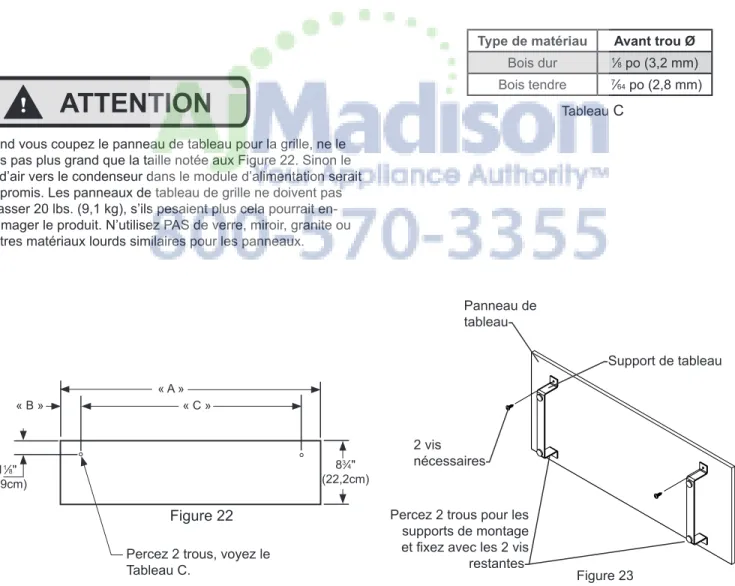
Hardwood 1/8" (3.2mm) Softwood 7/64" (2.8mm) "A" "B" "C" 83⁄4" (22.2cm) 11⁄8" (2.9cm)
CUSTOM GRILLE FACIA AND DOOR PANELS
-Facia bracket Facia panel-Screw 2 required-Figure 23 Figure 22
!
CAUTION
When cutting the facia panel for the grille do not make it larger than the size noted in Figure 22. Air flow to the con-denser in the power module would be compromised. Grille facia panels must not exceed 20 pounds (9.1kg), panels weighing more could cause product damage. Do NOT use glass, mirrors, granite or similar heavy materials for panels.
Mounting grille facia panel:
Cut the facia panel to the size shown in Figure 22 and Table B. Drill the two facia bracket screw pilot holes in the back side of the facia panel as noted in Figure 22. See Table C, for sizes. Fasten the two facia brackets to the back side of the facia panel with 2 of the screws provided. See Figure 22.
Align the facia brackets so they are parallel to the short edges of the facia panel and drill the remaining 2 bracket holes using the holes in the facia brackets as guides. Secure the bottom of the brackets with the 2 remaining screws.
The facia panel may now be mounted to the grille back.
Drill bottom 2 holes for mounting brack-ets and secure with remaining 2
screws.-Table B
Table C
CUSTOM GRILLE FACIA AND DOOR PANELS
!
WARNING
EXCESSIVE WEIGHT HAZARD
Use two or more people to move product.
Failure to do so can result in back or other injury.
Support door before removing
hinge-Step #1: Remove the Door
Support the door at the floor.
1. Loosen the set screw in the bullit cap with a 3⁄32" hex
key and remove the bullit cap from the hinge pin by sliding off. Do this to both the top hinge and at the bot-tom hinge. Set aside parts for later reassembly. 2. Loosen 5⁄16" Hex Nut underneath the hinge with a 1⁄2"
open end wrench, unscrew completely from the hinge pin.
3. Make sure the door is supported, and remove the hinge pin from the cabinet hinge with a flat bladed screw-driver.
4. Carefully lift the door off the lower hinge. 5. Assemble parts in reverse order.
Bullit cap--Set screw -5⁄16 Hex nut Top hinge pin-Door hinge--Cabinet hinge Figure 25
Custom Door Panel Installation Instructions
Determine Wood Screw Requirements
1. A #10 pan head wood screw should be used to prop-erly secure the overlay panel (See Figure 28). Screws are supplied with unit.
2. Use only pan head screws.
3. If your overlay panel is thinner than 5⁄8" (15.9 mm)
you will need to purchase shorter screws. The longer screws will break through the front of the panel.
-Bullit cap Set
screw--Door hinge
!
CAUTION
Door panels MUST NOT exceed 50 lbs. Do NOT use glass, mirrors, granite or similar heavy materials for panels. Pan-els weighing more than 50 lbs. may cause product damage. We recommend that the door load (panel and food) NOT exceed 90 lbs.
Solid door-
Screw-Door
Gasket-Door panel- Figure 28
"D" 683⁄16" (173.2cm) Figure 27 MODEL "D" M18AF-WP 165⁄16" (41.5cm) M24AF-WP 225⁄16" (56.7cm) M24AF-SP 225⁄16" (56.7cm) M30AF-WP 285⁄16" (71.9cm) M30AF-SP 285⁄16" (71.9cm) M36AF-WP 345⁄16" (87.2cm) M36AF-SP 345⁄16" (87.2cm) Table D
CUSTOM GRILLE FACIA AND DOOR PANELS
Cut the custom overlay panel to the dimensions shown in Figure 27 and Table D.
This is also a convenient time to locate and drill the holes for your handle. Most often the handle is to match that of the surrounding cabinetry. If your handle attaches from the back-side of the custom panel, locate the mounting holes while the panel is attached to the door and cabinet. After the panel is removed from the door, drill the mounting holes from the front, to the recommended diameter of the handle manufacturer. Counter bore the back-side of the panel so the screw heads do not interfere with the surface of the door.
Hinge and Gasket Adjustment
It is possible that doors may become out of adjustment in shipment.
If product is installed slightly “out of level”, doors may not line up properly. Check this BEFORE adjusting hinges.
Door gaskets occasionally compress in shipment. If gasket does not seal all around, warm slightly with a hair dryer and pull outward softly until magnet in gasket seals against cabinet.
To expose concealed door hinge screws, remove plug but-tons if present. All hinge sections attached to doors adjust left or right. Top and bottom cabinet hinges are also adjust-able in and out. See Figure 29 (shown without cabinet trim).
Figure 29
NOTE
Loosen door hinge screws to adjust door left and right. Loosen hinge
screws to adjust the door in and
out-HINGE AND GASKET ADJUSTMENTS
Step 3: Attach the Overlay Panel to the Door
1. Remove the gasket from the door front. (See Figure 28). Do this by pulling the gasket out of the chan-nel that holds it to the door front. This will expose the clearance holes for mounting the custom overlay panel. (See Figure 28).
2. Set the door on the overlay panel and align edges. (See Figure 28). Clamp panel in position and mark pilot hole locations. Pick the required pilot hole size from "Table E" below and drill the pilot holes ensuring not to drill all the way through the overlay panel.
Table E: Pilot Hole Drill Sizes for Wood Screws
Material Type #10 Wood Screw
Hardwood 9⁄64" (3.6mm) Diameter
Softwood 1⁄8" (3.2mm) Diameter
3. Insert wood screws through clearance holes and tighten to secure overlay panel.
4. Reinstall gasket into channel. Make sure the corners are fully inserted.
5. Install the door back on the cabinet by reversing the procedure in Step 1.
11⁄8"
(28.4mm)
Typical 1⁄4" (6.4mm) thick
battens-1⁄4" (6.4mm) Plywood / Panel 3⁄16" (4.8mm)
thick back
up-1⁄8" (4.8mm)
thick back
up-1⁄4" (6.4mm) Plywood / Panel 3⁄16" (4.8mm) thick battens-245⁄16" (61.8cm) -1⁄16" (1.6mm) rout 23⁄16" (55.6mm) 1⁄2" (12.7mm) Plywood / panel 5⁄16" (7.9mm)
Metal side panel 24"
(61cm) typical installation opening
Holes in roller
base-#8
screws-
Cap-Figure 30
Instructions for Fastening Side Panels to
freezer
1. Side panels should be 24 inches deep (or 24 5⁄16 inches
deep when tucked into the front trim). 2. Panel height to match installation height. 3. Install the side panels per drawings on the right.
To avoid damage to panels or flooring, raise panels slightly, to clear floor when installing.
Drill three (3) holes equal distance apart in vertical section of aluminum frame and install pan head screws as shown. Anchor side panel with screw as shown. Be sure screw used goes no more than 1⁄2 inch deep into product. Do NOT
overtighten.
NOTE
Kick Plate Installation
Use two (2) #8 sheet metal screws (supplied) to facilitate holding your kick plate in place. Mount screws in holes in roller base. Cover screw heads with caps supplied. (See Figure 31).
Installation Checks
• Anti-tip mounting bracket must be installed correctly and anchored to prevent cabinet from tipping forward. • Module should be engaged in the slots on the module
positioning brackets and seated on the foam seal with-out air gaps. Module positioning brackets should not be removed.
• All wires from the lower cabinet to module must be securely connected. If a problem is suspected, inspect both male and female plugs and ensure that the termi-nals in the plug are sufficiently forward to engage. • Cabinet must be level both side-to-side and
front-to-back. Front leveling legs should rest firmly on the floor. Cabinetry on both sides of the cabinet must be secure and level to prevent the cabinet from shifting when the doors are opened.
• Doors must not hit adjacent walls or countertops. • Gaskets must seal completely. If gaskets seal well, no
further adjustments need to be made.
• Do NOT overcrowd the shelves or block cold air ducts. • Do NOT install a freezer shelf closer than 8 inches
from the interior top.
• Do NOT allow packages to overhang sides or rear of shelves as this will block air circulation, making the freezer less efficient.
Common Installation Errors
• Any air leaks between the module and the cabinet will keep the cabinet from operating efficiently.
• The electric outlet must be located in a manner that will not interfere with module to cabinet alignment when the unit is pushed into place.
• Power cord to outlet sitting under the power module will create an air leak.
• Plugs from cabinet not connected to the power module. • Floor under products lower than finished floor making
the unit inaccessible for service. Floor under product must be strong enough to support weight of fully loaded freezer.
• Product not anchored properly (to prevent tipping). Bracket not secured to rear wall studs.
• Failure to properly level the cabinet and/or power mod-ule can result in defrost water overflowing.
CONGRATULATIONS! You are now the proud owner of a superb, beautiful and durable addition to your kitchen. The following information will help you get the most pleasure from your purchase.
Using your freezer:
Meats, fish and poultry pre-packed in plastic (self-service) wrap can be stored in the freezer for a couple of weeks. For longer freezer storage, wrap food in foil or other vapor-proof, moisture-proof freezer wrap. Frozen food contain-ers should be sealed tightly. If food is wrapped in “Butcher Paper”, remove and rewrap.
For more even temperature, space food so as not to restrict air flow, especially at rear.
Light frost may form on shelves when freezer door is open. After the door is closed, the air stream gradually removes the frost.
Varying amounts of frost will form occasionally in the freezer compartment, especially in areas near the top air return. This is normal.
If your freezer has an ice maker:
Install the freezer shelf in the third position down from the top of the shelf ladder (see Figure 32), this will position the ice bucket properly for operation of the ice maker.
First buckets may contain contamination from new instal-lation. Throw away the first two harvests or until the ice is free of discoloration and taste.
The ice maker makes ice once the freezer is cold. It will turn off automatically when the ice bucket is full, provided the bucket is properly positioned.
Lift the Stop Arm up out of the way when removing and replacing the container.
Never place fingers, foreign objects or food packages near the Ejector Blade.
Typical cycle of ice maker:
1. The ice maker fills with water.
2. When the water freezes, the motor rotates Ejector Blade against the ice. The blade stops when it touches the ice.
3. The heater releases the ice from the form.
USE AND CARE GUIDE
!
CAUTION
Motor--Ejector blade -Ice mold -Stop arm -Ice bucket -Shelf Figure 32When the bucket is full and in the proper (highest possible) position, the Stop Arm senses the ice and stops ice making. To stop the ice maker, whether full or not, simply raise the Stop Arm to “up” position. To restart, lower the Stop Arm. TIME PER CYCLE... Varies due to door openings, water temperatures, etc.
NORMAL ICE MAKER OPERATION
• Sounds to be expected: motor hum; creaking of the Ejector Blade; ice dropping into the bucket; running water; water supply valve snapping open.
• Frost formations in area of the ice maker: Since fresh water enters the form, frost build-up near the ice maker occurs. This will not affect the operation of your freezer. • Ice in the bucket for long periods may freeze together
and acquire odors. Discard stale pieces... Your ice maker will make more.
Position shelf tang in third slot down from top of shelf
ladder-NOTE
Temperatures:
The temperature is automatically controlled by a thermo-stat. The freezer control is located in the roof of the freezer. Three “3” is a good setting to start out with... Lower num-bers for warmer temperatures and higher numnum-bers for cold-est temperatures.
To help keep food fresh longer, some moisture is desirable in the food storage compartments. You may see it on the walls, or in the form of droplets of ice or “icicles”... especial-ly in hot or humid weather, or when frequent or extended door openings occur. This is normal, and not in any way harmful. If occasional “spot” build-ups occur, it is usually the result of the above, or of “overcrowding” of food. Occasion-ally remove such accumulation.
Defrosting:
Defrosting is automatic. It takes place in the Power Module, above and away from your food. For several minutes each day the compressor and interior fan will shut off, while any ice accumulation is removed from the coils.
Cleaning:
It’s easy to keep your Built-In freezer clean. Occasionally, clean the interior walls, shelves, door interiors and gaskets with a solution of two (2) teaspoons of baking soda dis-solved in a quart of lukewarm water. Harsh abrasives and cleaning powders are unnecessary and should never be used. Do not place parts in the dishwasher.
It is recommended that circuit breakers be shut off before cleaning. Wring excess moisture from sponge or cloth and avoid excess moisture, especially when cleaning in the vicinity of switches, lights or controls.
If your unit has a stainless steel interior, shelves or exterior door then use a stainless steel cleaner and a cloth to clean.
Condenser cleaning procedure:
The condenser is located behind the top grille. It is a part of the Power Module on its very right hand side. It has horizontal tubes with small diameter vertical wires and it is black in color. It is away from floor dust, however, it should be examined for dust accumulation at least two (2) times a year, and cleaned and/or vacuumed as
nec-essary. Remember to shut off the circuit breaker before
removing the grille and before exposing, cleaning, and/or vacuuming the condenser.
The louvered black or stainless steel grille is all one as-sembly. There are 3 ways to remove the grille. The most widely used method of mounting is with springs. The spring(s) are located behind the grille back. The spring(s) are mounted to the top of the cabinet and hook to the square holes in the grille back. To remove the grille, pull the grille forward and reach down to the spring and unhook it from the grille back. The grille back will be free to be removed.
The second method (optional) is with mounting brackets behind the grille back. Pull the grille forward about one (1) inch to expose the top screw in the brackets. Unscrew the screw to loosen it but do not remove it. Do this to each bracket. CAUTION, when the screw is loosened, the grille back will be loose, do not allow it to fall. Grasp the grille back on each side and tilt the top forward and lift upward to free the grille from its mounting.
A custom panel grille can be removed by lifting up on the facia panel and pulling forward on the facia panel. The grille back is held in place by a screw at the center going up into the adjacent cabinet. Remove this screw and the grille back can be removed.
The louvered grille is heavy so use care when removing. Now you can inspect the condenser for dust accumulation. Be sure to refasten top grille after cleaning to avoid injury, as grille could fall if not properly fastened.
-Condenser (behind grille) Power module
(on top of cabi-
The following suggestions will minimize the
cost of operating your refrigeration appliance.
1. Do not install your appliance next to a hot appliance, (cooker, dishwasher, etc.). heating air duct, or other heat sources.
2. Install product out of direct sunlight.
3. Ensure the front grille vents at front of unit above door are not obstructed and kept clean to allow ventilation for the refrigeration system to expel heat.
4. Plug your appliance into a dedicated power circuit. (Not shared with other appliances).
5. When initially loading your new product, or whenever large quantities of warm contents are placed within refrigerated storage compartment, minimize door openings for the next 12 hours to allow contents to pull down to compartment set-point temperature.
6. Maintaining a relatively full storage compartment will require less appliance run time than an empty compart-ment.
7. Ensure door closing is not obstructed by contents stored in your appliance.
8. Allow hot items to reach room temperature before plac-ing in product.
9. Minimize door openings and duration of door openings. 10. Use the warmest temperature control set-point that
meets your personal preference and provides the proper storage for your stored contents.
11. When on vacation or away from home for extended riods, set the appliance to warmest acceptable perature for the stored contents.
12. Set the control to the "off" position if cleaning the unit requires the door to be open for an extended period of time.
ENERGY SAVING TIPS AND PRODUCT SOUNDS
Product Sounds:
Your new freezer may make sounds unfamiliar to you. These sounds normally indicate that the freezer is operat-ing correctly. Note that hard surfaces around your product installation may make sounds more noticeable.
Following is a list of normal operating sounds that you may hear from your new appliance:
1. The compressor will cycle on and off to provide cooling as required. You may hear a click when the compressor cycles on, and may also hear pulsating, and/or, a pitched hum sound when the compressor is running. Run time may vary due to ambient temperature, usage/ door openings, and warm food loads.
2. The condenser fan will cycle on and off with the com- pressor to remove heat from the product. When running you may hear a motor hum, and an air rush noise as air is forced through the condenser heat exchanger. 3. The evaporator fan will also cycle with the compressor to provide cooling in the storage compartments. When running you may hear a motor hum and air noise. These noises will be noticeably louder when the storage partment doors are opened.
4. Automatic defrost requires the use of an electric heater to periodically remove frost from the evaporator heat exchanger. When in defrost you may hear a sizzling sound as water may contact the heater element. ditionally, during defrost you may hear water dripping or running as the defrost water is routed to the drain pan. 5. Defrost is controlled with a mechanical timer. During the compressor off cycle, in a quiet environment, you may hear a faint motor running, and/or clock ticking sound. 6. When the compressor cycles off you may temporarily hear gurgling, boiling, or water flowing sounds. This sults from the flow of refrigerant through the ant tubing as the system pressures equalize during the off cycle.
7. Faint popping noises may be heard at any time resulting from thermal contraction and expansion of components in the compartments as temperatures change throughout the refrigeration cycle.
8. If your unit is equipped with an icemaker you will hear a buzzing sound when the water supply solenoid valve is activated. You will also periodically hear the ice harvest which includes motor running noise, cracking and ment of cubes from the ice mold, and cubes dropping into the ice storage bin.
If Service is Required:
• If the product is within the first year warranty pe-riod please call AGA MARVEL Customer Service at 800.223.3900 for directions on how to obtain warranty coverage in your area.
• If the product is outside the first year warranty period, AGA MARVEL Customer Service can provide indepen-dent qualified servicers in your area. This listing of in-dependent qualified servicers is also available at www. agamarvel.com under the service and support section. • In all correspondence regarding service, be sure to
give the service number, serial number, (see page 4) located on your product’s serial plate, and proof of purchase.
• Try to have information or description of nature of the problem, how long the unit has been running, the room temperature, and any additional information that may be helpful in quickly solving the problem.
• Table F below is provided for recording pertinent infor-mation regarding your product for future reference.
For Your Records
Date of Purchase Dealer’s name Dealer’s Address Dealer’s City Dealer’s State Dealer’s Zip Code Appliance Serial Number Appliance Service Number Date Warranty Card Sent (Must be within 10 days of purchase).
TROUBLESHOOTING AND OBTAINING SERVICE
Table F
Before You Call for Service
If the unit appears to be malfunctioning, read through this manual first. If the problem persists, check the trouble-shooting guide below. Locate the problem in the guide and refer to the cause and its remedy before calling for service. The problem may be something very simple that can be solved without a service call. However, it may be required to contact your dealer or a qualified service technician.
Electrocution Hazard
Never attempt to repair or perform maintenance on the unit until the main electrical power has been disconnected. Turning the unit control "OFF" does not
remove electrical power from the units wiring.
!
WARNING
Troubleshooting
If product does not start when plugged in, check the follow-ing:
• Does the light go on when the freezer door is opened? If NOT, check, then...
• Is the cord from the lower cabinet plugged into the module?
• Is the power cord plugged in at the receptacle? • Is the circuit breaker or fuse ”on”? Check by
plugging another electric device into the outlet. • If light DID go on when the door was opened...
• Turn the defrost timer clockwise (might be in “defrost”) until compressor starts.
• If motor “hums”, but does not start...
• Check for adequate line voltage at the outlet. • The module may have been transported or
stored on its side or upside down, causing temporary displacement of motor oil. Let rest 24 hours, then plug in again.
WARRANTY
Entire Product - Limited One Year Warranty
AGA MARVEL warrants that it will supply all necessary parts and labor to repair or replace in your home, any com-ponent which proves to be defective in materials or work-manship, subject to the conditions and exclusions stated below, for the period of one year from date of sale.
Entire Product - Limited Second Year Additional Warranty
During the second year, from date of sale, AGA MARVEL will provide all necessary parts only to repair or replace any component which proves to be defective in materials or workmanship, subject to the conditions and exclusions below.
Sealed System - Limited Six Year Additional Warranty
During the second through seventh year, from date of sale, AGA MARVEL will supply all necessary parts and labor to repair or replace in your home, any portion of the hermeti-cally sealed refrigeration system, which consists of: the compressor, condenser, evaporator, dryer and all con-necting tubing, which proves to be defective in materials or workmanship, subject to the conditions and exclusions below.
Inner Liner - Limited Second Through Tenth Year Warranty
During the second through tenth year, from date of sale, AGA MARVEL will provide all necessary parts to repair or replace the refrigerator/freezer inner liner if the paint chips or rusts and proves to be defective in materials or work-manship.
The above warranties do not cover:
1. Customer education or instructions on how to use the refrigerator/freezer.
2. Any food loss due to product failure.
Nor do the above warranties cover failure of this prod-uct or its components due to:
3. Transportation or subsequent damages.
4. Use commercially or use other than normal household. 5. Improper installation, misuse, abuse, accident or
altera-tion, use on wiring not conforming to electrical codes, low voltage, failure to provide necessary maintenance or other unreasonable use.
6. Parts or service not supplied or designated by the fac-tory.
The above warranties also do not apply if:
1. The original Bill of Sale, delivery date or serial number cannot be verified.
2. The product is moved from place of original installa-tion.
THE WARRANTIES, SET FORTH HEREIN ARE THE ONLY WARRANTIES EXTENDED BY AGA MARVEL. ANY IMPLIED WARRANTIES, INCLUDING THE IM-PLIED WARRANTY OF MERCHANTABILITY, ARE LIMITED TO THE DURATION OF THESE EXPRESS WARRANTIES. IN NO EVENT SHALL AGA MARVEL BE LIABLE FOR ANY CONSEQUENTIAL OR INCIDEN-TAL DAMAGES OR EXPENSES RESULTING FROM BREACH OF THESE OR ANY OTHER WARRANTIES,
WHETHER EXPRESSED OR IMPLIED. Some states do
not allow the exclusion or limitation of consequential dam-ages or limitations on how long an implied warranty lasts, so the above exclusion or limitation may not apply to you. This warranty gives you specific legal rights and you may also have other rights which may vary from state to state. No person, firm or corporation is authorized to make any other warranty or assume any other obligation for AGA MARVEL. These warranties apply only to products used in any of the fifty states of the United States and the District of Columbia.
To obtain performance of this warranty, report any defects to:
1260 E. VanDeinse St. Greenville, Michigan 48838
For questions regarding coverage, contact your selling dealer or local distributor.
www.agamarvel.com
1260 E. VanDeinse St. Greenville MI 48838
Instructions
d’installation,
d’utilisation
et d’entretien
Construit en
Congélateur
M18AF
M24AF
M30AF
M36AF
Deballage de votre congélateur... ...3
Outils à avoir sous la main pour l’installation...3 Enregistrement de la garantie...4 Dimensions de porte plein de M(XX)AF...5 Dimensions de porte à revêtement plein de M(XX)AF...6 Considérations pour avant l’installation...7
Dimensions brutes d’ouverture recommandées...7
Choix de l’emplacement...7
Besoins électriques...8 Besoins en plomberie ...8
Installation en angle ...9 Installation de l’armoire...10
Considérations sur le dispositif anti-basculement...10 Mise à niveau de l’armoire...11 Installation du module d’alimentation...11
Placement du module d’alimentation en haut de l’armoire...11
Raccordements électriques de module d’alimentation...12 Installation de la vanne sur le tube pour fabrication de glaçons..13 Installation de la grille...14 Tableau de grille et panneaux de porte personnalisés...17
Montage du panneau de tableau de grille...17
Instructions d’installation pour panneau de porte personnalisé.18 Réglage de charnières et de joint...20
Instructions pour fixer les panneaux latéraux...21
Installation de plinthe...21 Contrôles d’installation...22 Erreurs d’installation fréquentes...22 Guide d’utilisation et d’entretien...23
Utilisation de votre congélateur...23
Températures...24
Dégivrage...24
Nettoyage...24
Procédure de nettoyage du condenseur...24 Conseils pour économie d’énergie...25 Bruits en provenance du congélateur ...25 Dépannage...26 Obtention de service...26 Garantie...27
Importantes instructions de sécurité
Les avertissements et les instructions de sécurité qui apparais-sent dans ce guide n’ont pas la prétention de couvrir toutes les conditions et situations possibles pouvant arriver. Il faut faire preuve de bon sens, de précautions et de soins, pour installer, utiliser ou entretenir cet appareil.
Reconnaissance des symboles, des mots
et des étiquettes concernant la sécurité.
AVERTISSEMENT –
Dangers ou pratiquesdan-gereuses avec une forte probabilité de blessures corpo-relles et/ou de dommages pour le produit.
ATTENTION
- Risques ou pratiques dangereuses pouvantentraîner des blessures individuelles, des dégâts matériels ou des dommages au produit.
REMARQUE -
Information importante pour réaliser uneinstallation et une utilisation sans problèmes.
!
AVERTISSEMENT
!
ATTENTION
REMARQUE
Outils à avoir sous la main pour l’installation
• Tournevis à pointe Phillips • Tournevis à lame plate
• Tourne-écrous 6 pans de calibre 1⁄4 et 5⁄16 po
• Niveau à bulles
• Perceuse avec foret N° 6 (0,204 po) • Clés à fourche de 1⁄4, 7⁄16 et 1⁄2 po
• Pince à jointure glissante (motoriste) • Clé à molette
• Mètre à ruban
• Clé à cliquet avec douille de 7⁄16 po
• Clé Allen 6 pans de 3⁄32 po RISQUE DE POIDS EXCESSIF
Utilisez deux personnes ou plus pour bouger et empiler le
produit. Sinon vous pourriez souffrir du dos ou d’une autre
blessure.
Contribuez à éviter des tragédies
L’emprisonnement d’enfants et leur asphyxie ne sont pas des problèmes du passé. Des épaves de réfrigérateurs abandonnés continuent de présenter un danger - même en restant dehors pour "juste quelques jours".
Si vous devez vous débarrasser de votre vieil appareil de refroi -dissement, veuillez suivre ces instructions pour aider à éviter des accidents possibles.
Avant de jeter votre vieux réfrigérateur ou congélateur :
• Démontez ses portes ou enlevez ses tiroirs.
• Laissez les étagères en place de façon à ce que des enfants ne puissent pas facilement monter dedans.
Enlèvement de l’emballage
Votre congélateur a été emballé pour l’expédition avec toutes les pièces pouvant être endommagées par le mouvement
solide-ment attachées. Coupez le matériau de fixation en bas du carton,
dépliez le carton par le bas et enlevez-le de l’appareil. Enlevez le sac en plastique, les cales d’angle en polystyrène expansé, et toutes les bandes adhésives maintenant la porte fermée et les composants à l’intérieur en place.
Le manuel de l’utilisateur est envoyé à l’intérieur du congé-lateur dans un sac en plastique, accompagné de la carte d’enregistrement de la garantie.
Important
Conservez votre carton et l’emballage jusqu’à ce que votre congélateur ait été complètement inspectée et trouvée en bon
état. S’il présentait des dommages, cet emballage serait néces -saire comme preuve qu’ils sont survenus durant le transit. Ensuite veuillez mettre toutes les parties de l’emballage au rebut de façon responsable, en particulier les sacs en plastique qui constituent un danger d’étouffement.
Note pour le client
Cette marchandise a été soigneusement et complètement inspec-tée avant de quitter notre usine. La responsabilité pour sa livrai-son sûre a été assumée par le revendeur à l’acceptation de cette expédition. Les réclamations pour perte ou dommages survenus durant le transit sont à adresser au revendeur.
NE RENVOYEZ PAS DE MARCHANDISE ENDOMMAGÉE AU FABRICANT – DÉPOSEZ UNE RÉCLAMATION AUPRÈS DU
REVENDEUR.
Si l’appareil a été livré étant sur le dos, ou y est resté pendant
une durée quelconque, laissez le module de alimentation
repo-DEBALLAGE DE VOTRE CONGÉLATEUR
!
AVERTISSEMENT
!
ATTENTION
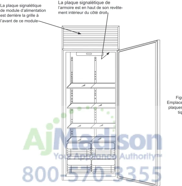
La plaque signalétique de
l’armoire est en haut de son revête-ment intérieur du côté droit-La plaque signalétique
de module d’alimentation est derrière la grille à l’avant de ce module
-Figure 1 Emplacements de
plaques signalé-tiques
Il est important que vous postiez votre carte de garantie immédi-atement après avoir pris livraison de votre congélateur.
Les informations suivantes seront nécessaires au moment de l’enregistrement de votre appareil :
Référence de service Numéro de série Date d’achat
Nom et adresse du revendeur
La référence de service et son numéro de série se trouvent sur la plaque signalétique qui est située dans le congélateur, du côté
Enregistrement de la garantie Figure 2 Plaque signalé-tique de module d’alimentation Figure 3 Plaque signalétique
ENREGISTREMENT DE LA GARANTIE
MODÈLE « A » « B » « C » M18AF-WS 18 po (45,7cm) 17 po (43,2cm) 4111⁄16 po (105,9cm) M18AF-SS 18 po (45,7cm) 17 po (43,2cm) 4111⁄16 po (105,9cm) M24AF-WS 24 po (61cm) 23 po (58,4cm) 4711⁄16 po (121,1cm) M24AF-SS 24 po (61cm) 23 po (58,4cm) 4711⁄16 po (121,1cm M30AF-WS 30 po (76,2cm) 29 po (73,7cm) 5311⁄16 po (136,4cm) M30AF-SS 30 po (76,2cm) 29 po (73,7cm) 5311⁄16 po (136,4cm) M36AF-WS 36 po (91,4cm) 35 po (88,9cm) 593⁄4 po (151,8cm) M36AF-SS 36 po (91,4cm) 35 po (88,9cm) 593⁄4 po (151,8cm) 273⁄16 po (69,1cm) 241⁄2 po (62,2cm) 197⁄8 po 73 po to 735⁄8 po (185,4cm to 187cm) 84 po to 845⁄8 po (213,4cm to 214,9cm) « A » 11 po (27,9cm) « C » « B » 1⁄2 po (12,7mm) 1⁄2 po (12,7mm) 29⁄16 po (6,5cm) Besoins électriques :
Un circuit secteur dédié avec terre en 115 V supportant 15 A est nécessaire. Appliquez toutes les normes de construction locales à l’installation de l’électricité et de l’appareil.
DIMENSIONS DE PORTE PLEIN DE M(XX)AF
MODÈLE « A » « B » « C » M18AF-WP 18 po (45,7cm) 17 po (43,2cm) 4111⁄16 po (105,9cm) M24AF-WP 24 po (61cm) 23 po (58,4cm) 4711⁄16 po (121,1cm) M24AF-SP 24 po (61cm) 23 po (58,4cm) 4711⁄16 po (121,1cm) M30AF-WP 30 po (76,2cm) 29 po (73,7cm) 5311⁄16 po (136,4cm) M30AF-SP 30 po (76,2cm) 29 po (73,7cm) 5311⁄16 po (136,4cm) M36AF-WP 36 po (91,4cm) 35 po (88,9cm) 593⁄4 po (151,8cm) M36AF-SP 36 po (91,4cm) 35 po (88,9cm) 593⁄4 po (151,8cm) 241⁄2 po (62,2cm) 73 po to 735⁄8 po (185,4cm to 187cm) 84 po to 845⁄8 po (213,4cm to 214,9cm) 11 po (27,9cm) « A » « B » 1⁄2 po (12,7mm) 1⁄2 po (12,7mm) « C » Besoins électriques :
Un circuit secteur dédié avec terre en 115 V supportant 15 A est nécessaire. Appliquez toutes les normes de construction locales à l’installation de l’électricité et de l’appareil.
- La prise électrique doit être placée à cet endroit pour les modèles de largeur 18 pouces (M18AF)
781⁄2" (199,4cm)
Minimum, type
Choix de l’emplacement
Placez l’ensemble congélateur dans la partie la plus fraîche de la pièce, à l’écart du rayonnement solaire direct, et de conduites ou de registres de chauffage.
Ne placez pas l’ensemble congélateur près d’appareils
dégag-eant de la chaleur, comme cuisinière, four ou lave-vaisselle. Si
cela n’est pas possible, une section de cloison ou une couche d’isolation supplémentaire entre les deux appareils procurera à un meilleur fonctionnement du congélateur.
N’installez PAS le congélateur dans un local où la température peut tomber en dessous de 60°F (15 °C) ou monter au-dessus de 110°F (43 °C). Le compresseur ne serait PAS à même de mainte -nir les bonnes températures intérieures.
La surface d’appui sous le produit DOIT être au même niveau ou
légèrement au-dessus que la finition de sol environnante, pour
faciliter son installation et son enlèvement.
REMARQUE
Figure 5Tableau A Figure 4
CONSIDÉRATIONS POUR AVANT L’INSTALLATION
841⁄4" to 847⁄8" (214cm) to (215,6cm) « B » minimum 22 po (55,9cm) « A » 24" (61cm) 24 po (61cm) 78 po (198,1cm) environ Emplacement recommandé de la conduite d’eau 20" (50,8cm) minimum (24" et largeur) MODÈLE « A » « B » M18AF 171⁄2 po (44,5cm) 171⁄4 po (43,8cm) M24AF 231⁄2 po (59,7cm) 20 po (50,8cm) M30AF 291⁄2 po (74,9cm) 20 po (50,8cm) M36AF 351⁄2 po (90,2cm) 20 po (50,8cm)
Besoins en plomberie :
Une conduite d’alimentation en eau pour la fabrication de glaçons, en tube de cuivre de diamètre extérieur 1⁄4" (6,4 mm) arrivant à
l’arrière de l’ouverture du meuble à environ 78" (198,1 cm) au-dessus du sol, selon sa hauteur de positionnement. Ce tube doit ensuite passer autour du côté droit du module d’alimentation et autour de l’avant de l’électrovanne de commande d’eau. Veuillez vous référer à la Figure 5.
Quand vous installez cette conduite d’eau pour faire les glaçons, assurez-vous d’y placer une VANNE DE COUPURE à un endroit commode avant le congélateur. L’eau doit arriver sous une pres-sion de 20 à 120 psi (138 to 827 kPa).
Il est également recommandé d’intercaler un FILTRE À EAU en ligne avant le congélateur, pour éviter un blocage de l’écoulement par des sédiments au travers de l’électrovanne.
Un emplacement idéal pour ces accessoires en ligne serait le dessus du meuble, derrière la grille, sur la droite du module d’alimentation.
Des vannes de coupure d’eau à perçage automatique sur la
conduite, et un tube en plastique, ne sont PAS approuvées pour
l’alimentation en eau de fabrication de glaçons.
CONSIDÉRATIONS POUR AVANT L’INSTALLATION
Besoins électriques :
Une prise secteur monophasé doit être disponible (115 V / 60 Hz / 15 A). Il est recommandé que le circuit d’alimentation secteur soit dédié à ce seul appareillage, et protégé (fusible temporisé ou disjoncteur). L’arrivée électrique doit se situer au moins à 781⁄2"
(199,4 cm) au-dessus du sol (Voyez la Figure 4).
Ce produit est équipé en usine d’un cordon secteur comportant
une fiche avec terre à trois broches. Il faut la brancher dans une
prise secteur correspondante avec terre, en conformité avec la norme électrique américaine (NEC) et les normes et
réglementa-tions locales applicables. Si le circuit ne comporte pas une prise
avec terre, le client doit en fournir une adéquate, c’est sa respon-sabilité.
Cet appareil doit être installé en conformité avec vos normes de construction et réglementations locales.
REMARQUE
!
AVERTISSEMENT
Risque de commotion électrique
• N’utilisez pas de rallonge secteur avec cet appareil.
Elles peuvent être dangereuses et causer un mauvais fonctionnement.
• Cet appareil ne doit sous aucun prétexte être installé
sur une alimentation électrique sans liaison de terre.
• N’enlevez pas la borne de terre de la fiche du cordon
secteur.
• N’utilisez pas d’adaptateur entre fiche et prise. • N’envoyez pas d’eau par éclaboussure ou par jet d’un
tuyau sur les appareils. Cela pourrait causer une commo-tion électrique, entraînant potentiellement des blessures graves voire mortelles.
Quand vous préparez votre ouverture brute, un panneau de rem-plissage de 3" (7,6cm) amovible est recommandé au-dessus de la grille. Pour enlever le module d’alimentation de l’armoire, son avant doit être soulevé comme c’est montré en Figure 6 pour un enlèvement pour intervention de service.
Remplissage amovible de 3" (7,6 cm) recommandé 845⁄8" (214.9cm) Maximum
INSTALLATION DE L’ARMOIRE
Figure 6 Installation en anglePour que la porte puisse complètement s’ouvrir à 90°, un rem -plissage de 3" (7,6 cm) doit être intercalé du côté cornière de la porte. Cela doit permettre un espacement pour la poignée de porte quand elle s’ouvre vers le mur. Voyez la Figure 7.
L’encastrement doit permettre de sortir l’ensemble de congélateur pour une opération de service.
Largeur d’armoire
Périmètre de l’armoire Remplissage de
3" au moins
INSTALLATION DE L’ARMOIRE
Figure 9 Congélateurs de largeur 18 ou 24" -Pièce de bois trans-versale -Cornière anti-basculement en haut de l’armoire -Poteau mural-Au moins deux vis dans le poteau mural Figure 10 Congélateurs de largeur 30 ou 36" Pièce de bois transversale--Poteau mural -Cornière anti-basculement en haut de l’armoire
-Au moins deux vis dans le poteau mural
Considérations sur le dispositif anti-basculement
Avant de placer l’armoire dans son ouverture, la profondeur de la
niche doit faire au moins 24 pouces (61 cm). Si cette profondeur est plus importante, il faut fixer une pièce de bois transversale
sur le mur dans les poteaux muraux à la hauteur des cornières anti-basculement. (Voyez les Figures 9 et 11). Glissez l’armoire en position et mettez-la d’aplomb avec le rouleau arrière réglable et les pieds avant de mise à niveau. (Voyez la section sur les pieds de mise à niveau en page 11).
Congélateur de largeur 18" ou 24" :
La cornière anti-basculement est fixée sur l’armoire et fait toute sa largeur. Localisez un poteau mural derrière l’armoire et fixez-y
la cornière anti-basculement avec au moins deux (2) vis #8 x 11⁄2”
fournies. Voyez la Figure 8.
Congélateur de largeur 30 ou 36" :
Localisez un poteau mural derrière l’ensemble qui convient pour
fixer au mur la cornière anti-basculement de 5" (12,7cm). La posi -tion de la cornière doit être sur la droite du module d’alimenta-tion et non derrière lui. Ne perturbez pas la position du joint de module d’alimentation sur le côté gauche de l’ensemble. Placez la cornière anti-basculement sur le haut de l’armoire, de niveau avec son dos. Marquez et percez au moins trois trous de 1⁄8” (3,2 mm)
dans le haut de l’armoire et fixez la cornière dessus avec fournies.
Fixez ensuite cette cornière au poteau mural avec au moins deux vis #8 de 11⁄2" fournies. Voyez la Figure 10 au moins trois vis #8