NASA/TM—2014–216641
Analysis of Low-Speed Stall Aerodynamics
of a Swept Wing with Laminar-Flow Glove
Trong T. Bui
Dryden Flight Research Center, Edwards, California
Click here: Press F1 key (Windows) or Help key (Mac) for help
January
2014
NASA STI Program ... in Profile
Since its founding, NASA has been dedicated to the advancement of aeronautics and space science. The NASA scientific and technical information (STI) program plays a key part in helping NASA maintain this important role.
The NASA STI program operates under the auspices of the Agency Chief Information Officer. It collects, organizes, provides for archiving, and disseminates NASA’s STI. The NASA STI program provides access to the NASA
Aeronautics and Space Database and its public interface, the NASA Technical Reports Server, thus providing one of the largest collections of aeronautical and space science STI in the world. Results are published in both non-NASA channels and by NASA in the NASA STI Report Series, which includes the following report types:
• TECHNICAL PUBLICATION. Reports of completed research or a major significant phase of research that present the results of NASA Programs and include extensive data or theoretical analysis. Includes compila- tions of significant scientific and technical data and information deemed to be of continuing reference value. NASA counter-part of peer-reviewed formal professional papers but has less stringent limitations on manuscript length and extent of graphic presentations.
• TECHNICAL MEMORANDUM.
Scientific and technical findings that are preliminary or of specialized interest, e.g., quick release reports, working papers, and bibliographies that contain minimal annotation. Does not contain extensive analysis.
• CONTRACTOR REPORT. Scientific and technical findings by NASA-sponsored contractors and grantees.
• CONFERENCE PUBLICATION. Collected papers from scientific and
technical conferences, symposia, seminars, or other meetings sponsored or
co-sponsored by NASA.
• SPECIAL PUBLICATION. Scientific, technical, or historical information from NASA programs, projects, and missions, often concerned with subjects having substantial public interest.
• TECHNICAL TRANSLATION.
English-language translations of foreign scientific and technical material pertinent to NASA’s mission.
Specialized services also include organizing and publishing research results, distributing specialized research announcements and feeds, providing information desk and personal search support, and enabling data exchange services.
For more information about the NASA STI program, see the following:
• Access the NASA STI program home page at http://www.sti.nasa.gov
• E-mail your question to help@sti.nasa.gov • Fax your question to the NASA STI
Information Desk at 443-757-5803
• Phone the NASA STI Information Desk at 443-757-5802
• Write to:
STI Information Desk
NASA Center for AeroSpace Information 7115 Standard Drive
Hanover, MD 21076-1320
NASA/TM—2014–216641
Analysis of Low-Speed Stall Aerodynamics
of a Swept Wing with Laminar-Flow Glove
Trong T. Bui
Dryden Flight Research Center, Edwards, California
Insert conference information, if applicable; otherwise delete
Click here: Press F1 key (Windows) or Help key (Mac) for help
Enter acknowledgments here, if applicable.
National Aeronautics and Space Administration
Dryden Flight Research Center Edwards, CA 93523-0273
Click here: Press F1 key (Windows) or Help key (Mac) for help
Available from:
NASA Center for AeroSpace Information 7115 Standard Drive
Hanover, MD 21076-1320 443-757-5802
1
Abstract
Reynolds-Averaged Navier-Stokes (RANS) computational fluid dynamics (CFD) analysis was conducted to study the low-speed stall aerodynamics of a GIII aircraft’s swept wing modified with a laminar-flow wing glove. The stall aerodynamics of the gloved wing were analyzed and compared with the unmodified wing for the flight speed of 120 knots and altitude of 2300 ft above mean sea level (MSL). The Star-CCM+ polyhedral unstructured CFD code was first validated for wing stall predictions using the wing-body geometry from the First American Institute of Aeronautics and Astronautics (AIAA) CFD High-Lift Prediction Workshop. It was found that the Star-CCM+ CFD code can produce results that are within the scattering of other CFD codes considered at the workshop. In particular, the Star-CCM+ CFD code was able to predict wing stall for the AIAA wing-body geometry to within 1 degree of angle of attack as compared to benchmark wind-tunnel test data. Current results show that the addition of the laminar-flow wing glove causes the gloved wing to stall much earlier than the unmodified wing. Furthermore, the gloved wing has a different stall characteristic than the clean wing, with no sharp lift drop-off at stall for the gloved wing.
Nomenclature
AIAA American Institute of Aeronautics and Astronautics AoA angle of attack
CD coefficient of drag CL coefficient of lift
CM coefficient of pitching moment CFD computational fluid dynamics DRE discrete roughness elements
ERA Environmentally Responsible Aviation LE leading edge
MAC mean aerodynamic chord MSL mean sea level
NASA National Aeronautics and Space Administration RANS Reynolds-averaged Navier-Stokes
SA Spalart-Allmaras turbulence model
SARGE Subsonic Aircraft Roughness Glove Experiment SCRAT SubsoniC Research AircrafT
T/C thickness to chord ratio
y+ normal distance to the wall in boundary layer wall units
Introduction
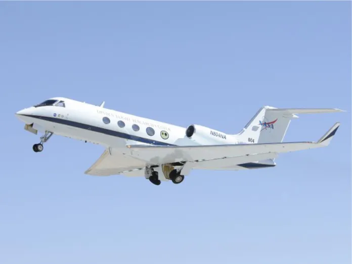
The National Aeronautics and Space Administration (NASA) Dryden SubsoniC Research AircrafT (SCRAT) aircraft tail number 804 is pictured in figure 1. This modified Gulfstream Aerospace Corporation (Savannah, Georgia) GIII aircraft is being proposed for use as the flight testbed for the Subsonic Aircraft Roughness Glove Experiment (SARGE) (ref. 1) project. A collaborative effort between NASA and Texas A & M University (College Station, Texas), SARGE proposes to conduct flight research on the effectiveness of the discrete roughness elements (DREs) in increasing the laminar-flow region on a generic subsonic transport swept wing for flight conditions representative of modern subsonic jetliners. The SARGE project directly supports the goal of the NASA Environmentally Responsible Aviation (ERA) Project of
2
enabling new technologies for the purposes of increasing aircraft efficiencies and reducing the adverse effects that aviation has on the environment. There are several reasons that SARGE is a good fit for the NASA Dryden SCRAT aircraft. First, the flight environment provides the very low freestream turbulence levels required to demonstrate the effectiveness of the DRE laminar-flow technology. Also, DREs have been found to produce significant increases in laminar-flow regions of a swept wing test article in flight at lower Reynolds numbers and Mach numbers (ref. 2). The Dryden SCRAT aircraft can help by expanding the flight research of the SARGE laminar-flow wing glove to higher Reynolds numbers and Mach numbers representative of typical full-scale jetliners.
ED12-0191-12c_800-600 Figure 1. NASA Dryden GIII SubsoniC Research AircrafT (SCRAT).
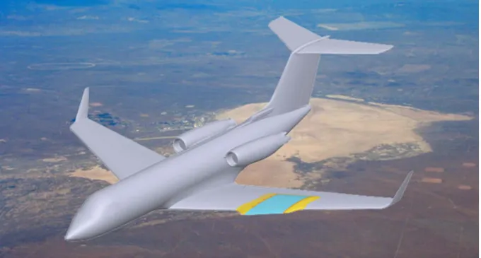
A conceptual sketch of the GIII aircraft modification is shown in figure 2. The SARGE DRE laminar-flow wing glove would be mounted only on the left wing of the SCRAT aircraft, resulting in an asymmetric aircraft configuration. The glove spans approximately 30 percent of the half span of the aircraft wing, occupying the midwing section, away from both the wing root as well as wing tip. The location of the glove was chosen to be away from the region of influence of the aircraft engine near the wing root for better flow quality over the glove, as well as away from the aircraft aileron, which is located towards the wing tip to avoid potential interference with the aerodynamic effectiveness of the left aircraft aileron. Micron-sized DREs mounted near the
3 leading edge of the wing glove provide the spanwise-periodic roughness variation that controls the unstable crossflow vortices and delays the transition to turbulence on the wing glove. The actual DREs are not directly modeled in the present computational fluid dynamics (CFD) simulations.
Figure 2. Conceptual sketch of the SARGE DRE laminar-flow wing glove mounted on the NASA Dryden SCRAT aircraft's left wing.
All of the proposed SARGE flight-test points will be done around trimmed aircraft cruising flight conditions for the SCRAT aircraft. Hartshorn (ref. 3) has found that the wing glove produces very small changes in aircraft aerodynamics at aircraft cruising flight conditions. Laminar-flow wing glove flight testing has been conducted extensively in the past using a wide variety of aircraft such as the JetStar (Lockheed Martin, Bethesda, Maryland), Learjet (Learjet, now Bombardier Aerospace, Wichita, Kansas), Boeing 757 (The Boeing Company, Chicago, Illinois), F-111 (General Dynamics, now Lockheed Martin, Bethesda, Maryland), F-14 (Grumman, now Northrop-Grumman Corporation, West Falls Church, Virginia), F-15 (McDonnell Douglas, now The Boeing Company, Chicago, Illinois), and F-16XL (General Dynamics, now Lockheed Martin, Bethesda, Maryland). A preliminary literature search has found no mention of stalls as significant issues in all of these previous flight research efforts. The laminar-flow wing glove proposed for the left wing of the SCRAT does not represent a significant departure from these previous laminar-glove flight research efforts. Therefore, it is not expected that modified aircraft stall characteristics would present serious problems for conducting the SCRAT aircraft SARGE wing glove research flights at high-speed cruising flight conditions. However, low-speed stall aerodynamics of the gloved wing need to be analyzed in order to ensure flight safety for the takeoff and landing portions of the SARGE glove test flights.
The laminar-flow wing glove introduces many significant physical modifications to the left wing of the SCRAT aircraft, as listed below:
4
• Modifications of the basic wing airfoil section for 30 percent of the half span of the aircraft wing include: smaller leading edge (LE) radius, longer chord length, a smaller thickness over chord (T/C) ratio, and modified airfoil camber line.
• There are two leading-edge snags introduced by the glove extending beyond the LE of the unmodified aircraft wing.
• Four standard aircraft wing vortex generators (out of a total of 31) are removed to make room for glove installation on the left wing. The right wing retains the full 31 vortex generators.
The DREs are expected to provide significantly more laminar flow over the wing glove than the equivalent area on the unmodified GIII aircraft wing. Also, the laminar-flow airfoil design of the wing glove modifies the transonic flow over the wing as compared to the normal GIII aircraft wing airfoil. For example, at an aircraft Mach number of 0.75, the shock wave on the upper surface of the wing in the laminar glove area is further downstream compared to the shock location of the clean wing at the same flight Mach number.
Finally, the glove is mounted only on the left wing, resulting in an asymmetric aircraft configuration. This asymmetric mounting of the glove on the left wing only could create undesirable asymmetrical forces and moments should the gloved left wing stall earlier than the unmodified right wing. The main objective of the current analysis effort is to determine if the addition of the laminar-flow wing glove to the left wing causes left wing stalls to occur before the unmodified right wing of the airplane.
In this report, the Star-CCM+ polyhedral unstructured CFD code is first validated for low-speed wing stall predictions using the wing-body geometry from the First American Institute of Aeronautics and Astronautics (AIAA) CFD High-Lift Prediction Workshop (ref. 4). The effects of grid sizes and turbulence models on the accuracy of the CFD stall predictions are quantified. Finally, the low-speed stall aerodynamics of the gloved wing are presented and compared with the unmodified wing aerodynamics.
CFD Code Validation Study
Steady Reynolds-Averaged Navier-Stokes (RANS) CFD simulations have been found to be qualitatively accurate for predicting low-speed wing stalls in the First AIAA CFD High-Lift Prediction Workshop (ref. 4). An assessment of the prediction capability of twenty-one participants from eight countries using a variety of different structured as well as unstructured CFD codes was made in this workshop. Although there was significant scattering in the CFD predictions as compared with the benchmark wind-tunnel test data, it was shown in reference 4 that the angle of attack (AoA) of the wing at stall could be predicted with reasonable accuracy. Since the CFD code Star-CCM+ was not considered in this workshop, it is necessary to conduct a CFD code validation study to ensure that the Star-CCM+ high-lift results are reliable.
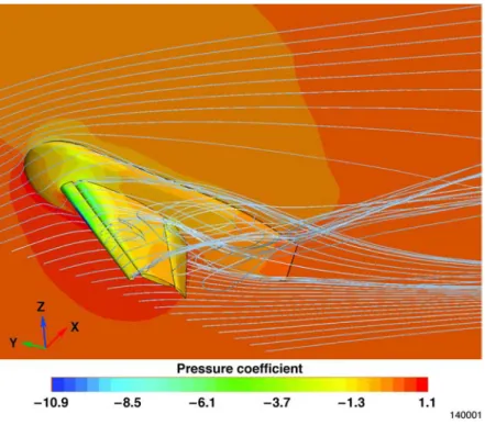
Figure 3 illustrates the First AIAA CFD High-Lift Prediction Workshop Configuration 1 wind-tunnel geometry that was used for the present validation study. In this figure, contours of pressure coefficient on the wing-body surface and the plane of symmetry are shown together with the flow streamlines, illustrating the post-stall separated flows over this AIAA wing-body configuration. The selected configuration is one of the two configurations considered by the AIAA workshop. In this configuration, the LE slat is deflected by 30 degrees and the flap is
5 deflected by 25 degrees. The Star-CCM+ meshes were created incorporating the guidelines and best practices provided in references 5 and 6. Some of the more useful guidelines include:
• Far-field located at a distance of ~100 reference chords (ref. 5).
• Surface grid spacing should be approximately 0.3 percent of the airfoil chord (ref. 6). • Initial y+ wall spacing normal to the wing surface should be less than one (ref. 5) or
equal to one (ref. 6).
• Geometric stretching ratio not more than 1.2 (ref. 6).
Figure 3. Geometry for the First AIAA CFD High Lift Prediction Workshop configuration 1. The Star-CCM+ code validation study was conducted at a free-stream Mach number of 0.2 and a Reynolds number based on the mean aerodynamic chord of 4.3 million as specified by the AIAA workshop. All runs were conducted fully turbulent. From a turbulence models sensitivity study, it was found that, using the same mesh with the same initial y+ normal wall spacing values less than 1, the automatic y+ turbulence modeling option in Star-CCM+ caused the wing-body CFD simulations to stall too early, and the low-y+ option produced more accurate stalled AoA predictions in better agreement with the AIAA workshop results.
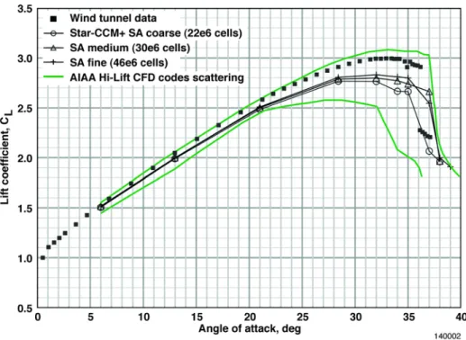
As can be seen in figures 4 to 6 below; the lift, drag, and pitching moment coefficients computed from the Star-CCM+ CFD simulations quantitatively agree with the wind-tunnel data from the First AIAA CFD High-Lift Workshop. Results using the Spalart-Allmaras turbulence model are shown for three different mesh sizes: coarse (22 million cells), medium (30 million cells), and fine (46 million cells). It can be seen that the Star-CCM+ results are within the bounds of scattering of the results from most of the CFD codes used in this workshop. There was even more scattering in the CFD codes considered in the workshop comparison than indicated by the green boundaries in figures 4–6, and the green boundaries in these figures exclude the outliers found in the workshop’s results.
6
Figure 4. Star-CCM+ CFD code validation results for lift coefficient, Mach 0.2, Reynolds number based on mean aerodynamic chord of 4.3 million.
Figure 5. Star-CCM+ CFD code validation results for drag coefficient, Mach 0.2, Reynolds number based on mean aerodynamic chord of 4.3 million.
7 Figure 6. Star-CCM+ CFD code validation results for pitching moment coefficient, Mach 0.2, Reynolds number based on mean aerodynamic chord of 4.3 million.
Although there are disagreements with the wind-tunnel test data, it can be seen that the Star-CCM+ CFD results are within the scatterings of most of the CFD codes considered in the workshop and tend to follow the trends of the other CFD codes well. For example, most of the codes including Star-CCM+ under predict both the drag coefficient as well as the pitching moment coefficient (less negative), as shown in figures 5 and 6, respectively. Most importantly, for the objective of the current work, it can be seen in figure 4 that Star-CCM+ is capable of predicting wing stall to within 1 degree of AoA of the wind-tunnel test data. The wind-tunnel lift coefficient data in figure 4 shows that wing stall occurs at an AoA of 36 degrees. The coarse-grid Star-CCM+ CFD result shows a stall AoA value of 35 degrees. Both the medium- and fine-grid Star-CCM+ results show a stall AoA of 37 degrees, indicating grid convergence for this particular result.
Laminar-Flow Gloved Wing Stall Analysis
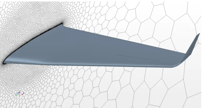
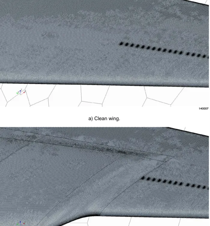
Figures 7(a) and (b) show the CAD models for the Star-CCM+ CFD swept wing simulations. The clean wing is shown in figure 7(a), and the gloved wing is shown in figure 7(b). Only one wing on a plane of symmetry was modeled in the current CFD simulations to concentrate as many grid cells as possible on the wing. The vortex generators can be seen as a row of small dots toward the wing tip in these figures. For clarity, only the mesh on the symmetry plane is displayed in figures 7(a) and (b). There is such fine mesh spacing on the wing surfaces that these wings would appear solid black if the wing mesh is turned on in figures 7(a) and (b). Figures 8(a) and (b) illustrate a closed-up view of both wing configurations in the vicinity of the vortex generators near the wing glove location, with the surface mesh turned on. It can be seen that four vortex generators are missing in the gloved wing in figure 8(b) as compared to the clean wing in figure 8(a). The appropriate number of vortex generators was gridded for both the clean wing (31 vortex generators total) as well as the gloved wing (27 vortex generators total).
8
As discussed in the introduction section above, four standard aircraft wing vortex generators are removed to make room for glove installation on the left wing. Two different mesh sizes were considered: medium (35 million cells) and fine (45 million cells). All of these results were obtained using the low-y+ turbulence modeling option in Star-CCM+ with the first y+ value from the wall being approximately 0.1. It was found in the CFD code validation study section above that this y+ option produces the most accurate stall results. All CFD runs were conducted fully turbulent. Although there is flow transition on the laminar glove, it is likely that the flow rapidly transitions to mostly turbulent as soon as the AoA is increased above the design angle for the laminar-flow glove due to the off-design pressure gradient over the upper surface of the glove at higher AoA.
Approximately 19 prism layers were used in the boundary layer over the wing with an overall prism layer thickness of 0.055 m. Far-field boundaries are placed approximately 100 times the mean aerodynamic chord (MAC) away from the wing. For the medium mesh, surface target mesh size is 0.3 percent MAC with a minimum surface mesh size of 0.075 percent MAC. Both of the surface mesh grow rate and volume cell grow rate are set at 1.2. All of the simulations were started at a low AoA of just below 6 degrees then gradually increasing until past lift stall. The converged solution at a lower AoA is used to start the next higher AoA calculation. Convergence is achieved when forces and moments, as well as all of the residuals become either constant for fully attached wing flows or periodic for the separated, post-stalled wing flows.
Figure 9 summarizes the Star-CCM+ CFD wing lift coefficient stall results for the clean wing as well as the gloved wing for the low-speed, low-altitude flight conditions of 120 knots and 2300 ft above mean sea level (MSL), which is approximately ground-level at Edwards Air Force Base (Edwards, California). Before stalls, the gloved wing is seen to have slightly higher lift than the clean wing. Hartshorn (ref. 3) has shown that the airplane can compensate for this small difference in lift with no problems. The gloved wing stalls much earlier than the clean wing. Furthermore, the stall characteristic of the gloved wing is different from the clean wing. When the clean wing stalls at an AoA of approximately 17 degrees, there is an abrupt loss of lift. However, when the gloved wing stalls at an AoA of approximately 10.5 degrees, there is no abrupt loss of lift. Instead, the lift remains more or less constant at its value at AoA of 10.5 degrees. Although not captured in these steady RANS CFD simulations, the post-stall flows over the wing are likely very unsteady for both the clean as well as gloved wings.
9 a) Clean wing.
b) Gloved wing.
10
a) Clean wing.
b) Gloved wing (4 vortex generators missing).
Figure 8. Closed-up view of the Star-CCM+ CFD grid for the clean wing and gloved wing with vortex generators.
11 Figure 9. Star-CCM+ CFD wing lift coefficient stall results, 120 knots, 2300 ft above MSL. Four vertical gray dotted lines in this figure denote the trimmed AoA for four flap configurations for the normal (ungloved) wing of the clean airplane. When no aircraft flap is used (0-degree flap), it can be seen that the trimmed AoA of the clean airplane is actually higher than the stall AoA of the gloved wing. Since the left gloved wing stall occurs before the normal aircraft trimmed AoA, asymmetrical wing stall can occur without warning if no flap is used. When the aircraft flaps are deflected to 10, 20, or 39 degrees, the trimmed AoA values of the aircraft can be reduced to below the gloved wing stall AoA, possibly allowing aircraft operation at this low-speed, low-altitude flight condition. Note that the laminar-flow glove would likely change the stall characteristics of the wing with flap deflected, and an analysis of gloved wing stalls with flap deflections will be needed before flap deflections can be considered as mitigation. In addition to flap deflections, higher takeoff and landing speeds could be considered to increase the gloved wing stall margins.
Figure 10 compares the flows over the clean wing, figure 10(a), and the gloved wing, figure 10(b), at the aircraft AoA of just below 12 degrees. As shown in figure 9 above, at this AoA the clean wing still provides lift with plenty of stall margin while the gloved wing has stalled. It can be seen that the flow remains smooth and fully attached for the clean wing, while for the gloved wing; the flow over the glove is separated causing the gloved wing to stall earlier than the clean wing. A possible explanation for the different stall characteristic of the gloved wing seen in figure 9 is provided by examining figure 10(b). Only the flow over the glove and its vicinity is stalled, with the rest of the flows over the wing remaining attached and providing some lift. Therefore, there is no sharp lift drop-off at gloved wing stall as compared to the clean wing stall.
12
a) Unstalled clean wing.
b) Stalled gloved wing.
Figure 10. Comparison of flows over unstalled clean wing versus stalled gloved wing at an AoA of just below 12 degrees, 120 knots, 2300 ft above MSL.
13
Conclusions and Recommendations
In conclusion, Reynolds-Averaged Navier-Stokes computational fluid dynamics (CFD) analysis was conducted to study the low-speed stall aerodynamics of a swept wing modified with a laminar-flow wing glove. The stall aerodynamics of the gloved wing were analyzed and compared with the unmodified wing at one low-speed and low-altitude flight condition. First, the Star-CCM+ polyhedral unstructured CFD code was validated for wing stall predictions using the wing-body geometry from the First AIAA CFD High-Lift Prediction Workshop. It was found that the Star-CCM+ CFD code can produce results that are within the spread of other CFD codes considered at the workshop. In particular, the Star-CCM+ CFD code was able to predict wing stall for the AIAA wing-body geometry to within 1 degree of angle of attack (AoA) as compared to the benchmark wind-tunnel test data. Current analysis results show that the addition of the laminar-flow wing glove causes the modified and gloved aircraft wing to stall much earlier than the unmodified wing. The gloved wing also has a different stall characteristic than the clean wing, with no sharp lift drop-off at stall. These results have important flight safety consequences, since the left gloved wing could stall prematurely before the right clean wing, producing a serious asymmetric aircraft configuration issue. It is possible to use flap deflections in order to reduce the aircraft’s trimmed AoA to values below the stall AoA of the gloved wing, potentially allowing the laminar-flow gloved wing aircraft to operate at the low-speed flight condition under consideration. However, an analysis on gloved wing stalls with flap deflections needs to be done before this can be considered as mitigation. In addition, higher aircraft takeoff and landing speeds might be used to increase the gloved wing stall margin.
Only 0-degree flap was considered in this work. The addition of the laminar-flow wing glove could change the stall characteristics of the wing with deflected flaps. Also, ground effects were not considered in this study and could potentially modify the stall characteristics of the gloved wing. Both of these issues should be analyzed in future studies before the gloved wing aircraft could be flown.
It is further recommended that the modified gloved wing lift, drag, and moment results obtained in this report need to be used in a 6-degrees of freedom GIII flight simulation software to determine gloved wing aircraft stall margins during takeoffs and landings.
References
1. Belisle, Michael J., Matthew W. Roberts, Thomas C. Williams, Matthew W. Tufts, Aaron A. Tucker, William S. Saric, and Helen L. Reed, “A Transonic Laminar-Flow Wing Glove Flight Experiment: Overview and Design Optimization,” AIAA-2012-2667, 2012.
2. Carpenter, Andrew, William S. Saric, and Helen L. Reed, “Laminar Flow Control on a Swept Wing with Distributed Roughness,” AIAA-2008-7335, 2008.
3. Hartshorn, Fletcher, “Analysis of Asymmetric Aircraft Aerodynamics Due to an Experimental Wing Glove,” AIAA-2011-3352, 2011.
4. Rumsey, C. L., J. P. Slotnick, M. Long, R. A. Stuever, and T. R. Wayman, “Summary of the First AIAA CFD High-Lift Prediction Workshop,” Journal of Aircraft, Vol. 48, No. 6, November-December 2011, pp. 2068-2079.
14
5. Slotnick, Jeffrey P., Judith A. Hannon, and Mark Chaffin, “Overview of the First AIAA CFD High Lift Prediction Workshop (Invited),” AIAA-2011-862, 2011.